


The
POWER
PRESENTATION PRODUCTS
In
Instruction Book for
MULTI-MASK IMAGER
DA-LITE SCREEN COMPANY, INC.
3100 North Detroit Street
Post Office Box 137
Warsaw, Indiana 46581-0137
Phone: 574/267-8101
800-622-3737
Fax: 574/267-7804
http:// www.da-lite.com
e-mail: info@da-lite.com

IMPORTANT SAFETY INSTRUCTIONS
When using your video equipment, basic safety precautions
should always be followed, including the following:
1. Read and understand all instructions before using.
2. Position the cord so that it will not be tripped over, pulled,
or contact hot surfaces.
3. If an extension cord is necessary, a cord with a current
rating at least equal to that of the appliance should be used.
Cords rated for less amperage than the appliance may
overheat.
4. To reduce the risk of electric shock, do not disassemble this
appliance. Contact an authorized service dealer when repair
work is required. Incorrect reassembly can cause electric
shock when the appliance is used subsequently.
5. The use of an accessory attachment not recommended by
the manufacturer may cause a risk of fire, electric shock, or
injury to persons.
SAVE THESE INSTRUCTIONS
1
MOUNTING THE FRAME
Professional mounting techniques should be adhered to. Da-Lite Screen Company cannot be liable for substandard or
faulty installations.
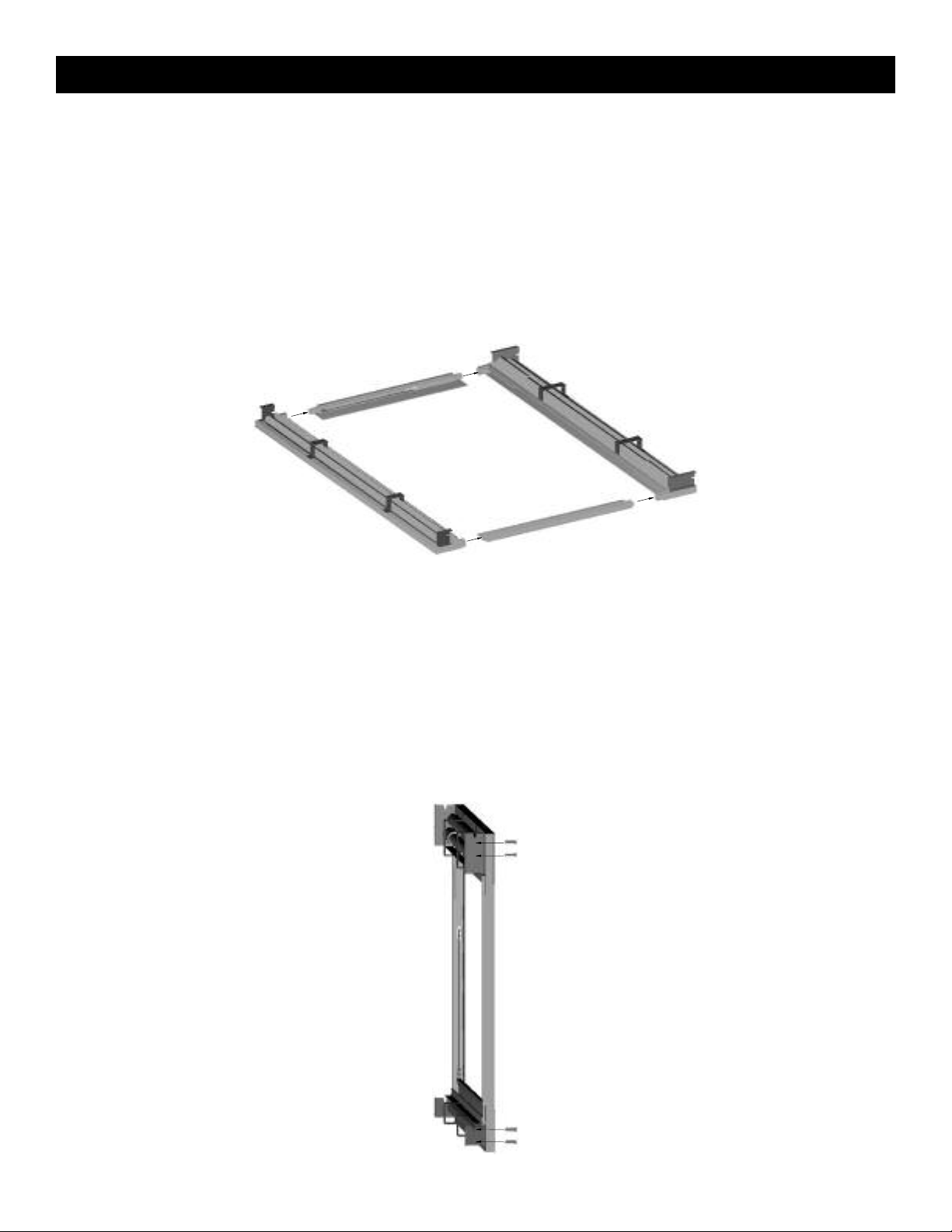
Frame Assembly
Assembly of the screen should be in a clean environment.
1. Connect the four frame pieces by matching the colored tapes on the ends of the frame pieces. See Figure 1.
2. Secure with the supplied 5/16" setscrews.
FIGURE 1
Positioning the frame on the wall
1. Without the screen fabric attached, position the frame on the wall at the location you desired.
2. Make sure the unit is level and plumb. (You may need to use shims between the brackets and the wall to achieve
vertical plumb.)
3. Mark the position of the bracket holes on the wall. See Figure 2.
CAUTION: If the screen is not mounted so that it is level and plumb, horizontal masking may jam on retraction.
!
▲
FIGURE 2
2
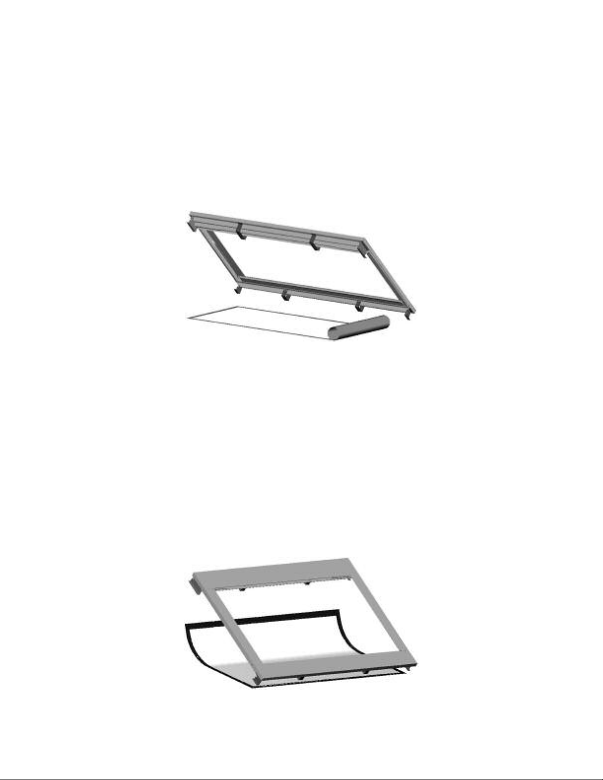
Unpacking and unrolling the screen
The viewing side of the screen surface is rolled to the inside. The screen surface is rolled lengthwise.
1. Remove screen from packaging.
. On a clean floor, unroll the screen surface viewing side up.
2
3. Allow the paper to unroll between backside of the screen surface and floor. See Figure 3.
CAUTION:
!
▲
• Be careful not to touch or scratch the viewing side of the surface with fingernails and any sharp tools.
• Do not use any tools to fasten the screen surface to the frame.
• Do not fold or crease the screen.
FIGURE 3
Attaching the screen surface to frame
1. Place the frame over the screen surface.
2. While lifting the frame with one hand, snap the screen surface onto the frame. Gently allow the screen to stretch
onto snaps. See Figure 4. Attach the snaps on the top corners and top horizontal first, lift the frame to a vertical
position to finish attaching the rest of the snaps.
FIGURE 4
3

Tensioning the bottom masking panel
1. Carefully remove all tape strips securing surfaces around rollers. Slats should move freely. See Figure 5.
2. Locate the spring tension cables on either side of the unit.
. Connect the eye snap to the eyelet on the bottom masking panel bar. See Figure 5. You will need to pull the cable
3
slightly.
4. Repeat for the other side.
SPRING TENSION CABLE
SLAT
SURFACE
TAPE STRIP
EYE SNAP
EYELET
SLAT
FIGURE 5
ELECTRICAL WIRING
Electrical wiring is required for each mask roller motor. The vertical masking systems have one motor at the frame top.
Horizontal masking systems have one motor at the frame top and one at the bottom.
A motor requires standard 120V/220V input. All connections are made to the electrical box on the audience left side of
the unit.
FIGURE 6
HORIZONTAL MASK CONNECTION
VERTICAL MASK CONNECTION
HORIZONTAL MASK CONNECTION
4

MULTI-MASK IMAGER INSTALLATION
Installing the high voltage switch control (standard)
Three standard 3-position wall switches are supplied. The high-voltage control is connected to the electrical source. It
alternates directions of mask motion by means of a hot lead, using the 3-position switches.
120V WIRING DIAGRAM
TO MOTOR
DOWN
RED
UP
BLACK
WHITE
COMMON
HITE
W
LACK
B
LACK WITH
B
ELLOW
Y
C COMMON
A
AC HOT
120V. 60-HZ 2.5 MAX. AMP
OPERATING SWITCH,
SWITCH BOX, AND
PLATE FURNISHED
WITH SCREEN. (SPDT
WITH CENTER OFF)
IN MULTIPLE CONTROL
INSTALLATIONS THIS SWITCH
IS REPLACED BY THE LOW
OLTAGE CONTROL,
V
OPERATED FROM PUSH
BUTTON STATIONS.
OCKER
R
WITCH
S
UP
FF
O
OWN
D
SIDE VIEW
OF SWITCH
AND BOX
RED
THIS SWITCH CANNOT BE USED WITH LVC.
Note: A single switch cannot be used to operate more than
one screen. Contact the factory for further information.
240 VOLT WIRING DIAGRAM
FOR STANDARD WALL SWITCH:
Da-Lite offers two styles of 240 volt
wall switches for standard operation.
Please see wiring diagram included in
wall switch box included with screen.
5

HANGING THE SCREEN ON THE WALL
Attach the wall brackets to the wall using appropriate fasteners at previously marked locations.
Attach the Side Covers to the frame by sliding the Bolts on the Side Cover tube into the openings on the top and bottom
brackets. See Figure 7.
OPENING
SIDE
SIDE
COVER
COVER
FIGURE 7
OPERATING THE MASK
When you lower or retract a mask, it will stop at its present limit. If an obstacle (such as a person or furniture) gets in the
path of a mask as it is lowered, you should use the switch control to stop the mask’s motion; it will not automatically stop
if it hits an obstacle.
NOTE: The horizontal masking panels move more slowly than the vertical masking panels. The slower motion allows you to adjust
the image area with greater precision.
When a mask is not in use, you should store it in the fully retracted position.
CAUTION: Do not operate the motor when any of the following occurs:
!
▲
• The unit emits any smoke, heat, abnormal noise or unusual odor.
• The unit is damaged in some way, such as damage from a water leak.
If any of these situations occur, call a qualified service person.
ADJUSTING THE MASK EXTENSION
CAUTION: Improper adjustment of the limit switches can cause irreparable damage to a mask itself, resulting in voiding the
!
factory warranty.
▲
The extension and retraction limit switches have been preset at the factory. In general, we advise you to avoid
readjusting these switches.
In some cases, to enable proper alignment of the displayed image on the screen, you may need to adjust the extension
of a mask. If adjustment to the extension is necessary, carefully follow these instructions.
WARNING! A mask is fully retracted when the batten is flush with the bottom of the case. Do not attempt adjustments with a
retraction (UP) limit switch that will further retract a mask. Incorrect adjustment of that switch will cause severe mask damage.
Please consult the factory if you have any questions.
6

Modifying the extension of the mask
You can increase the extension of a mask up to 3" past the factory preset stop, or you can decrease the extension by
pproximately 4-6" from the factory preset stop. Do not attempt to modify a mask extension beyond these recommended
a
amounts.
The limit switches are accessed through openings located on the left side of the frame as shown in Figure 8.
1
2
3
4
5
6
HORIZONTAL MASK
VERTICAL MASK
SCREEN
HORIZONTAL MASK
FIGURE 8
Horizontal mask units have limit switches at the top and bottom of the screens, a set for each roller tube.
WARNING! The up limit switch(es) retract the batten further into the unit. Adjusting it is not advised. Refer to 1, 3 or 5 as appropriated
in Figure 8.
To increase a mask’s fully extended (mask down) stop position:
1. Lower the mask to its current stop position.
2. Locate the down limit switch(es) located on the left side of the frame. Refer to 2, 4 or 6 as appropriate in Figure 8.
Use an Allen wrench to turn the switch in a counterclockwise direction. If the power is on, the mask will drop
incrementally as the switch is turned. NOTE: One complete turn of the switch will make approximately a 1/2" change in the
mask’s stop position.
To decrease the screen extension:
1. Lower the mask until it is extended about halfway down.
2. Locate the down limit switch(es) located on the left side of the frame. Refer to 2, 4 or 6 as appropriate in Figure 8.
Use an Allen wrench to turn the switch in a clockwise direction. NOTE: One complete turn of the switch will make
approximately a 1/2" change in the mask’s stop position.
3. Activate the mask in the down direction until it reaches the newly reduced stop position. Repeat this procedure
until the desired stop position is reached.
Once you have made the adjustment, whenever you lower the mask, it will automatically stop at the new position.
7

SCREEN CARE AND CLEANING
With reasonable care, you expect many years of trouble-free use of your Da-Lite projection screen.
e encourage you to keep your screen clean. Avoid getting any foreign material on the screen. It may not be possible to
W
remove scratches, paint, ink, etc.
General maintenance
The screen surface on your Multi-Mask Imager is delicate. Special attention to these instructions should be followed
when cleaning.
• A draftsman-style brush may be used to lightly whisk away any loose dirt or dust particles. (This type of brush is
usually available at office supply stores.)
• For tougher spots, use a mild solution detergent, water and a soft cloth. Rub lightly. Blot with a damp sponge to
absorb excess water.
Do not use any other cleaning materials on the screen.
Replacement parts and service
No user-serviceable parts are contained within the unit. Contact your dealer or the factory if you require part replacement
or service.
8

TROUBLESHOOTING
Refer to the following guidelines if you encounter a difficulty in the operation of your Da-Lite Multi-Mask Imager screen.
Problems related to electrical or motor function may require a qualified service person or electrician.
Should you have a problem that is not addressed here, call the Da-Lite Screen Company.
SYMPTOM
1. Mask won’t operate.
2. Mask won’t roll up or down (even
though power is available.
3. Mask roller chatters when power is
activated.
4. Unit hums in up mode (Mask has
already retracted).
CAUSE
(a) No 120V/220V power available.
(b) Outboard switching problem.
(a) Bad connection at switch.
(a) Can be caused by voltage drop, bad
connections or a defective switch.
(a) The mask batten is retracting too far
into the case.
Failure to correct can damage motor.
Do not use the unit until this problem
is resolved.
SOLUTION
(a) Check to see if the circuit breaker
has switched off. Reset if needed.
(b) Check outboard switching apparatus.
Check voltage availability
Contact an Electrician.
(a) Have an electrician or qualified
service person check the connection
as follows:
• If you have a high voltage control
switch, check switch line
connections.
• If you have a low voltage control
unit, check switch line
connections.
(a) Have an electrician or qualified
service person check all hook-ups
including all outboard wiring.
(a) Have a qualified service person
adjust the UP limit switch. Turn the
adjusting screw clockwise.
5. Mask drops when up direction is
activated (grinding noise occurs).
6. Mask continues past bottom stop
position.
7. Batten retracts too far into frame.
8. Dirt, fingerprints, marks, etc. on
screen surface.
9. Indentations appear on screen
surface.
10. Horizontal mask jams upon
retraction.
(a) Drop in voltage.
(a) White limit switch is out of
adjustment.
(a) Yellow limit switch out of
adjustment.
Failure to correct can damage motor.
Do not use the unit until this problem
is resolved.
(a) Improper handling of screen.
(a) Debris or particles adhering to screen
due to static cling.
(a) The unit was not level and plumb
when mounted.
(a) Mask motor requires full voltage.
Have an electrician or qualified
service person check the available
voltage.
(a) Readjust the DOWN limit switch.
See pp. 6-7 of this manual.
(a) Have a qualified service person
adjust the UP limit switch. See pp.
6-7 of this manual.
(a) Brush off or use a mild detergent
solution with clean rag or cotton
swab.
(a) Check back of screen; gently brush
debris away by hand.
(a) Remount the unit making sure that it
is level and plumb.
9

10

Printed in U.S.A. 94727 Rev. 7/09
 Loading...