

Page 1
INSTRUCTION BOOK FOR
Large Dual Masking Electrol
Page 2

Important Safety Instructions
When using your video equipment, basic safety precautions
should always be followed, including the following:
1. Read and understand all instructions before using.
2. Position the cord so that it will not be tripped over, pulled,
or contact hot surfaces.
3. If an extension cord is necessary, a cord with a current rating
at least equal to that of the appliance should be used. Cords
rated for less amperage than the appliance may overheat.
4. To reduce the risk of electric shock, do not disassemble this
appliance. Contact an authorized service dealer when repair
work is required. Incorrect reassembly can cause electric
shock when the appliance is used subsequently.
5. The use of an accessory attachment not recommended by
the manufacturer may cause a risk of ire, electric shock,
or injury to persons.
Save These Instructions
2
Page 3
Pre-Installation
1. Carefully unpack screen.
2. Make sure to recheck measurements of screen location
before installation.
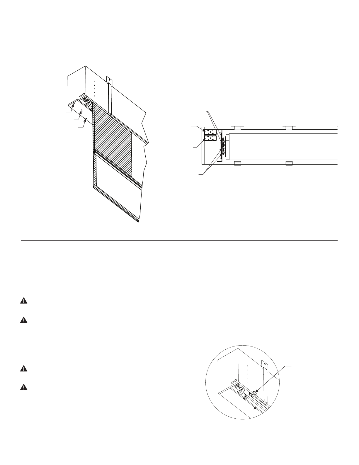
Drywall Screw
Access Panel
Machine Screw
Figure 1
3. Do not remove the wrapping paper or pull the orange string
Screens 14' wide and over use an ironing board to latten the
fabric. The ironing board is part of the access panel (Fig. 3).
Adjustment
Knob “Down”
Mask Motor
Wiring Box
Screen Motor
Wiring Box
Adjustment
Knob “Up”
until the screen is installed.
Figure 2
Installation
NOTE: Unit is not to be installed in air handling space.
Hangers (If required)
1. Make sure hangers are placed to it into the
pre-determined notches.
2. Level unit lengthwise with a carpenter’s plum level.
CAUTION! Do not completely seal in unit. Access room must
be allowed for motor repair or fabric replacement.
ATTENTION! Ne ixez pas complètement l'unité. Un espace doit
être laissé pour pouvoir réparer le moteur ou remplacer la
toile.
3. Remove the slat retainer brackets from the front of the case (Fig. 3).
4. Remove wrapping paper and tape strips.
CAUTION! Do not cut wrapping paper or tape with knife
or any sharp tool. Remove by hand.
ATTENTION! Ne coupez pas le papier d'emballage ou le ruban
adhésif avec un couteau ou un outil tranchant. Retirez à la
main.
NOTE: Must be installed in accordance with the requirements of
the Local Building Codes, the Canadian Electrical Code (CEC), CAN/
CSA C22.1 and the National Electric Code (NEC), NFPA 70. An
appropriate disconnect device shall be provided as part of the
building installation.
6. Test installation by carefully running surface up and down several
times. Be prepared to stop screen. Standard Duty Cycle: 1 MIN. ON /
10 MIN. OFF.
NOTE: The picture surface, when rolled down, should have at least
a full wrap and a half around the roller. Do not allow any part of the
roller to become exposed.
Slat Retainer
Brackets
(3 Screws)
5. Install electrical hook up that applies to your unit. Make sure to
review your Electrical Installation Checklists and wiring diagrams
(included) for either 110 volt switch, 220/240 volt switch, or DRC
low voltage control.
Figure 3
Ironing Board
(Screens 14' Wide And Over)
3
Page 4

Screen Adjustment For 120V Screens
CAUTION! The mask should not be ield adjusted for more or less drop.
ATTENTION! Le masque ne doit pas être ajusté sur place pour régler la chute.
Surface travel is stopped automatically in the fully opened and closed positions by limit switches that are properly adjusted at Da-Lite.
Should it be necessary to adjust for more or less drop of picture, proceed in the following manner:
NOTE: Use a screw driver or allen wrench to make adjustments.
More screen drop
1. Remove access panel (Fig. 1).
2. Place operating switch in “down” position.
3. When the screen stops, turn the “down” limit knob (Fig. 2)
one-quarter turn counterclockwise. Test by raising picture
surface approximately two feet, then lower again. Repeat until
desired picture surface position is attained.
NOTE: Must leave 11/2 wraps of fabric on roller!
4. Replace access panel.
Large Dual Masking Electrol® Instructions
Junction Box
Located in
Screen Housing
120V Wiring Diagram
Down
Common
Ground
Up
Black
Red
White
Green
Less screen drop
1. Remove access panel. (Fig. 1).
2. Raise picture surface approximately two feet
above desired level.
3. Place operating switch in “of” position.
4. Turn the “down” limit knob (Fig. 2) one-quarter turn
clockwise. Test by raising picture surface approximately
two feet, then lower again. Repeat until desired picture
surface position is attained.
5. Replace access panel.
Junction Box
Located in
Screen Housing
Black
Red
White
Green
Up
Down
Common
Ground
Mask Motor
IMPORTANT NOTE:
Switch junction box must be connected to
ground using the procective earthing screw.
4
4 – Wire
Mask Motor
Double Gang JBox
Provided By Da-Lite
Of
Down
Up
Mask
Screen
4 – Wire
Screen Motor
Up
Of
Down
Black (Hot)
White (Common)
Ground Wire
Screen Motor
Protective Earthing
Stud Inside Junction Box
115 V. AC 60 Hz
Input
Page 5

Screen Adjustment For 220V/240V Screens
CAUTION! The mask should not be ield adjusted for more or less drop.
ATTENTION! Le masque ne doit pas être ajusté sur place pour régler la chute.
Surface travel is stopped automatically in the fully opened and closed positions by limit switches that are properly adjusted at Da-Lite.
Should it be necessary to adjust for more or less drop of picture, proceed in the following manner:
NOTE: Use a screw driver or allen wrench to make adjustments.
More screen drop
1. Remove access panel (Fig. 1).
2. Place operating switch in “down” position.
3. When the screen stops, turn the “down” limit knob (Fig. 2)
one-quarter turn counterclockwise. Test by raising picture
surface approximately two feet, then lower again. Repeat until
desired picture surface position is attained.
NOTE: Must leave 11/2 wraps of fabric on roller!
4. Replace access panel.
Large Dual Masking Electrol® Instructions
Junction Box
Located in
Screen Housing
240V Wiring Diagram
Down
Common
Ground
Up
Brown
Black
Blue
Green/Yellow
Less screen drop
1. Remove access panel. (Fig. 1).
2. Raise picture surface approximately two feet
above desired level.
3. Place operating switch in “of” position.
4. Turn the “down” limit knob (Fig. 2) one-quarter turn
clockwise. Test by raising picture surface approximately
two feet, then lower again. Repeat until desired picture
surface position is attained.
5. Replace access panel.
Junction Box
Located in
Screen Housing
Brown
Black
Blue
Green/Yellow
Up
Down
Common
Ground
Mask Motor
IMPORTANT NOTE:
Switch junction box must be connected to
ground using the procective earthing screw.
4 – Wire
Mask Motor
Double Gang JBox
Provided By Da-Lite
Of
Down
Up
Mask
Screen
4 – Wire
Screen Motor
Up
Of
Down
Brown (Hot)
Blue (Common)
Ground Wire
Screen Motor
Protective Earthing
Stud Inside Junction Box
220 V. AC 50 Hz
Input
5
Page 6

Large Dual Masking Electrol® Instructions
Length = Fabric Width + 19", All Sizes
11 1⁄2"
19 1⁄2"
Mounting Bracket
(3 Provided)
Electrical
Outlets
Motor End
9 1⁄2"
9 1⁄2"
Suggested Methods Of Installation
NOTE: Unit is not to be installed in air handling space.
Ceiling Type Hanger
Picture
Surface
Wall Or Ceiling Mount With Hangers
Wall type hangers and ceiling type hangers are standard
equipment. One set is supplied with each screen. Useful
for recessed installations.
For Exposed Installation
If the screen is to be mounted in an exposed position, it may be covered
with inished plywood, veneer, paneling, plastic wall covering or a valance.
Wall Type Hanger
Picture
Surface
Rafters
Picture
Surface
Recessed Above Ceiling
Other methods of installation will suggest
themselves in new buildings where it would
be an easy matter to provide a recess for
the screen to conceal it when not in use.
Do not seal in—allow access.
6
Page 7

Troubleshooting
Symptom Cause Solution
Screen will not operate
and motor does not hum.
Incorrect line voltage.
Branch circuit fuse blown. Replace fuse.
Tripped branch circuit breaker. Reset circuit breaker.
No power to operating switch or junction.
Power at junction box
Thermal overload tripped.
Broken wire in the “down” or “up” position. Check for continuity. Cut o old splice and reconnect.
Defective motor, limit switch or capacitor. Replace motor assembly. NOTE: Motor is a sealed assembly.
Verify 115125V (or 220240V). If insuicient voltage, rewire
incoming electric line..
Check above. Tighten all loose wire connections.
Correct any improper connections.
“Down” Position
Check for power across black and white leads.
“Up” Position
Check for power across red and white leads.
Let motor cool down for 15 minutes. Try again.
Motor capacitor burned out.. Replace motor assembly.
Incorrect stopping position in
downward direction.
Incorrect stopping position in
upward direction.
Noise.
NOTE: Screen will operate
with a low pitched hum.
Coasting. Defective brake. Replace motor assembly.
Lost roller wrap. See instructions below..
“Down” limit switch out of adjustment See installation instructions.
Lost roller wrap. See instructions below..
“Up” limit switch out of adjustment Adjust “up” limit switch. See installation instructions
Gear Noise. Replace motor assembly.
Restoring Lost Roller Wrap
1. Tape a strap to the bottom of the screen surface.
2. Push strap over back of roller.
3. Feed fabric as you pull strap to draw fabric over top of roller.
4. Remove tape and strap.
7
Page 8

LIMITED ONE YEAR WARRANTY ON DALITE PRESENTATION PRODUCTS
Milestone AV Technologies LLC warrants certain Da-Lite branded products to the original purchaser only, to be free from defects in
materials and workmanship for a period of one (1) year from the date of purchase by the original purchaser; provided they are properly
operated according to Da-Lite's instructions and are not damaged due to improper handling or treatment after shipment from the
factory.
This warranty does not apply to equipment showing evidence of misuse, abuse or accidental damage, or which has been tampered
with or repaired by a person other than authorized Da-Lite personnel.
Da-Lite’s sole obligation under this warranty shall be to repair or to replace (at Da-Lite’s option) the defective part of the merchandise.
Returns for service should be made to your Da-Lite dealer. If it is necessary for the dealer to return the screen or part to Da-Lite,
transportation expenses to and from Da-Lite are payable by the purchaser and Da-Lite is not responsible for damage in shipment.
To protect yourself against damage or loss in transit, insure the product and prepay all transportation expenses.
TO THE MAXIMUM EXTENT PERMITTED BY APPLICABLE LAW, THIS WARRANTY IS IN LIEU OF ALL OTHER WARRANTIES, EXPRESS
OR IMPLIED, INCLUDING WARRANTIES AS TO FITNESS FOR USE AND MERCHANTABILITY. Any implied warranties of itness for use,
or merchantability, that may be mandated by statute or rule of law are limited to the one (1) year warranty period. This warranty gives
you speciic legal rights, and you may also have other rights, which vary from state-to-state. TO THE MAXIMUM EXTENT PERMITTED
BY APPLICABLE LAW, NO LIABILITY IS ASSUMED FOR EXPENSES OR DAMAGES RESULTING FROM INTERRUPTION IN OPERATION
OF EQUIPMENT, OR FOR INCIDENTAL, DIRECT, OR CONSEQUENTIAL DAMAGES OF ANY NATURE.
In the event that there is a defect in materials or workmanship of a Da-Lite product, you may contact our Sales Partners at PO Box 137,
Warsaw, IN 465810137, (574) 2678101, (800) 6223737.
IMPORTANT: THIS WARRANTY SHALL NOT BE VALID AND DALITE BRANDED PRODUCTS SHALL NOT BE BOUND BY THIS
WARRANTY IF THE PRODUCT IS NOT OPERATED IN ACCORDANCE WITH THE DALITE WRITTEN INSTRUCTIONS.
Keep your sales receipt to prove the date of purchase and your original ownership.
A Milestone AV Technologies Brand
3100 North Detroit Street
Warsaw, Indiana 46582
P: 574.267.8101 or 800.622.3737
F: 574.267.7804 or 877.325.4832
E: info@da-lite.com
www.da-lite.com
DL0246 (Rev. 2) 09.14
© 2014 Milestone AV Technologies LLC. Printed in U.S.A.
22624
 Loading...