

Page 1
INSTRUCTION BOOK FOR
Large Cosmopolitan® Electrol
®
Page 2
Important Safety Instructions
When using your video equipment, basic safety precautions should always be followed, including the following:
1. Read and understand all instructions before using.
2. Position the cord so that it will not be tripped over, pulled, or
contact hot surfaces.
3. If an extension cord is necessary, a cord with a current rating at
least equal to that of the appliance should be used. Cords rated
for less amperage than the appliance may overheat.
Save These Instructions
Pre-Installation
1. Carefully unpack screen and remove outer wrapping from
case.
2. Remove the black tape and rubber bands from the slat bar
after the case has been installed.
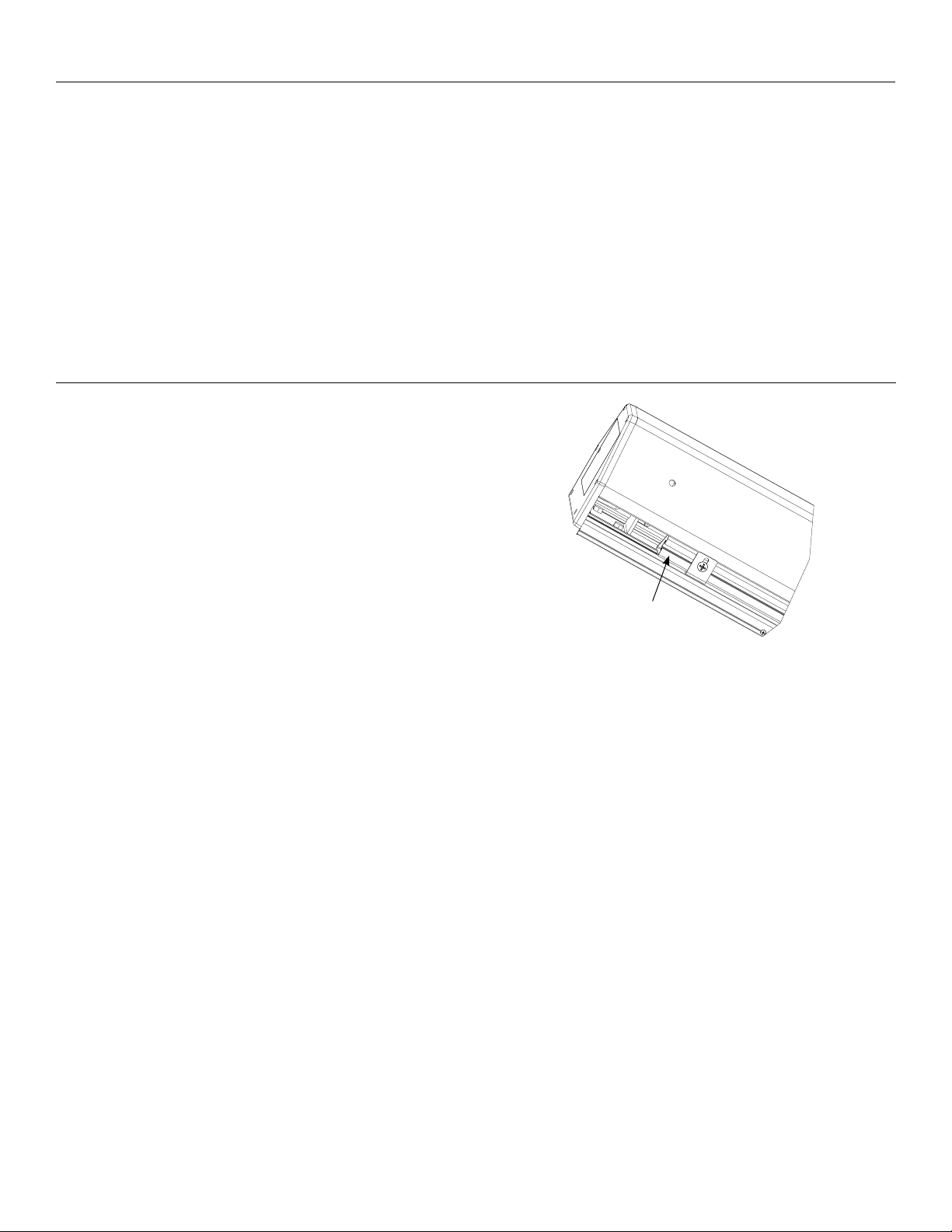
Ironing Board
The Large Cosmopolitan Electrol includes an ironing board to
latten the fabric (long strip attached). The ironing board is part
of the screen case. Do not remove. Contact Da-Lite if the ironing
board is in need of adjustment. (Fig. 1).
4. To reduce the risk of electric shock, do not disassemble this
appliance. Contact an authorized service dealer when repair
work is required. Incorrect reassembly can cause electric shock
when the appliance is used subsequently.
5. The use of an accessory attachment not recommended by the
manufacturer may cause a risk of ire, electric shock, or injury to
persons.
Ironing
Board
Figure 1
2
Page 3
Installation
Carefully unpack screen and remove outer wrapping from case.
Remove the black tape and rubber bands from the slat bar after the case has been installed.
The Large Cosmopolitan Electrol comes with brackets to allow for wall mount or ceiling mount installations. Procedures for each
method are as follows:
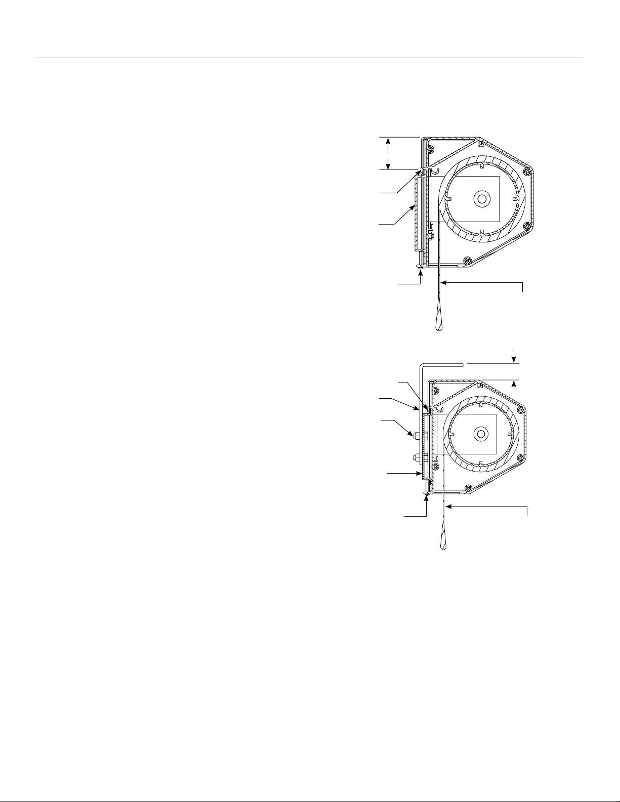
Wall Mount
2
1. The wall mount bracket should be fastened to wall studs or
some reinforcement within the wall. Concrete or brick walls
require special fasteners and anchors.
2. The wall bracket has holes spaced at 16" and 24" to align with
most wall studs.
3. The bracket must be level and plumb.
4. Keep in mind you will need at least 23/4" between the ceiling
and the top of the wall mount bracket to be able to position
the case on the bracket.
5. Mount the screen case on the wall bracket as shown in
igure 2. Be sure the case is fully seated on the bracket.
Tighten the stop screws against the wall bracket.
Ceiling Mount
Case Hook
Wall Mount
Bracket
Stop Screw
"
Viewing Surface
(Audience Side)
Figure 2
1. Be sure the ceiling has adequate reinforcement to attach the
screen brackets.
2. Attach the ceiling brackets to the wall mount bracket using
the supplied 5/16" x 3/4" bolts, washers and nuts.
3. Position the ceiling bracket assembly on the ceiling and
attach with 5/16" bolts (not supplied). The bolts should be
long enough to pass through the drywall or ceiling tile and
penetrate at least 11/2" into the reinforcement in the ceiling.
4. Mount the screen on the wall bracket as shown in igure 3. Be
sure the case is fully seated on the bracket. Tighten the stop
screws against the wall bracket.
1 ⅛"
Case Hook
Ceiling Mount
Bracket
⁄ x ¾" Bolt
Nut and Lock
Washer
Wall Mount
Bracket
Stop Screw
Viewing Surface
(Audience Side)
Figure 3
3
Page 4
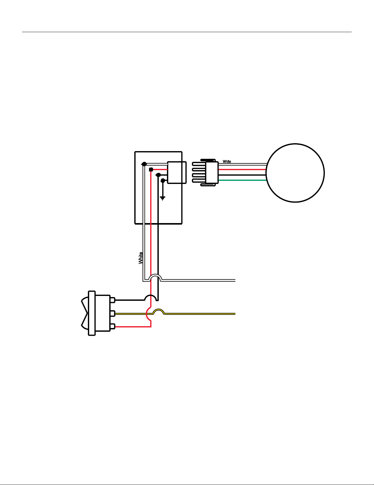
Installation For Screens Without A Built-In Low Voltage Control
Internal wiring has been completed at the factory. Installer must route power to the wall switch and to the junction box located on the
left end of the screen case.
See wiring diagram below for wire connections.
NOTE: This screen can only be controlled by a single 120VAC or 240VAC wall switch. To use multiple switches, an optional low voltage
control must be used.
120V Wiring Diagram
For Standard Wall Switch
Junction Box
Located In Left Endcap
NOTE: A single switch cannot be used
to operate more than one screen.
Contact the factory for further
information.
SPDT Switch with
Center Of
Up
Of
Down
Black
Red
White
Red (Up)
Black (Down)
AC (Common)
AC Hot 120VAC 60HZ 1 AMP
Black/Yellow
White
Red
Black
Green
Motor
This Switch Can Not
be used with LVC.
240 VOLT WIRING DIAGRAM FOR STANDARD WALL SWITCH:
Da-Lite ofers two styles of 240 volt wall switches for standard operation.
Please see wiring diagram in wall switch boxes included with screen.
4
Page 5

Screen Adjustment For Screens Without A Built-In Low Voltage Control
Screen travel is stopped automatically in the down and up positions by the limit switches that are preset at the factory.
No further adjustment is necessary.
If you need to make minor stop position adjustments see the appropriate step below.
SETTING THE DOWN LIMIT POSITION
NOTE: One turn of the limit screw equals approximately 2" of
screen travel.
To Reduce Screen Drop: Turn the down limit switch screw clockwise
to decrease the amount of screen drop. Run the screen down to test
the stop position. If the screen drops too far, raise the screen about
one foot and adjust the limit switch again. Repeat until the
desired position is set.
To Increase Screen Drop: Turn the down limit switch screw
counterclockwise to increase the amount of screen drop. Run the
screen down to test the stop position. If the screen does not drop
enough, raise the screen about one foot and adjust the limit switch
again. Repeat until the desired position is set. Do not adjust for more
drop than what was ordered. At least 11/2 wraps of fabric must remain
on the roller.
Down Limit
Switch Access
Hole
Up Limit Switch Access
Through Case Opening
Figure 4
SETTING THE UP LIMIT POSITION
CAUTION: Do not allow the slat bar to wrap over the top
of the roller when the screen is rolling into the case.
The screen could be damaged.
ATTENTION: Évitez que la barre inférieure ne s'enroule au
dessus du cylindre lorsque l'écran est enroulé dans le caisson.
L'écran pourrait être endommagé.
Screen Travels Into Case Too Far: Turn the up limit switch screw
clockwise to decrease the amount of travel. Run the screen up to test
the stop position. If the screen does not stop properly, lower the
screen about one foot and turn the limit switch again. Repeat until the
desired position is set.
Screen Does Not Travel Far Enough Into Case: Turn the up limit
switch screw counterclockwise to increase the amount of up travel.
Run the screen up to test the stop position. If more travel is desired,
lower the screen about one foot and adjust the limit switch again.
Repeat until the desired position is set.
5
Page 6

Installation for 120V Screens with A Built-In Low Voltage Control
UP
STOP
DOWN
UP
STOP
DOWN
120V Wiring Diagram
3-conductor 2024 gauge wire can be used in place of the
supplied RJ14 cable to connect the wall switch. Connect the
BUS terminals on the wall switch to the corresponding BUS
terminals on the splitter board.
Up Limit
Led
Tactile Button
BUS
COM
5V
Down Limit
Bus
Tactile Button
Front of
Wall Switch
Back of
Wall Switch
RJ22
Jack
RJ22 Jack
(Connection to
Wall Switch)
RJ22
Inputs
IMPORTANT NOTE: The wall switch is REQUIRED to make any
limit switch adjustments, EVEN if a third party control system is
used. Therefore, it is advised to wire the switch or provide a
3-conductor connection that is accessible.
RJ22
Output
Up (Dry Contact)
Down (Dry Contact)
Common (Both)
Bus (Bus)
5V (Bus)
RJ45
Receptacle
RJ45 Jack
Data
Cable
RJ14 Pin-Outs (Tab Is Facing Up)
Bus (RP Data)
RQ Data
+5V
Ground
Supplied RJ14 cable
White
Green
Red
Black
Power
Wire
White
(Common)
Black
(Hot)
Power Input 120VAC / 60Hz
Green (Ground)
(Ground–Must be Connected
to Building Ground)
RJ22 Pin-Outs (Tab Is Facing Up)
+12V
Bus (RP Data)
RQ Data
+5V
Ground
RQ Clock
Standard RJ22 can be used in place of RJ14 cable
Blue
Yellow
Green
Red
Black
White
RJ45 Pin-Outs (Tab Is Facing Up)
Manual 2
+12V
Bus (RP Data)
RQ Data
+5V
Ground
RQ Clock
Manual 1
Brown
Blue
Yellow
Green
Red
Black
Orange
Purple
6
Page 7

Screen Adjustment For 120V Screens With A Built-In Low Voltage Control
1. Locate the wall switch and remove the cover plate from the
3-button wall switch and remove the switch from the junction box.
2. Locate the two tactile buttons on the back of the switch. They are
square silver with black round buttons. See wiring diagram.
3. To adjust the down limit switch, press and hold the down tactile
button until the LED on back of switch turns solid red. This will put
the motor in limit set mode. Turn the wall switch over and use
the down button on front of switch. Press and hold until the
desired travel position is reached. If you travel to far down you
can press the up to move the screen upward. If you press and let
go of either up or down button the motor will do a small jog in
that direction for iner adjustment of screen. Once desired
position is reached turn switch over press and hold down tactile
button until the LED on back of switch blinks red twice. The down
limit is now set.
4. To adjust the up limit switch, press and hold the up tactile button
until the LED on back of switch turns solid green. This will put the
motor in limit set mode. Turn the wall switch over and use the up
button on front of switch. Press and hold until the desired travel
position is reached. If you travel to far up you can press the down
to move the screen downward. If you press and let go of either up
or down button the motor will do a small jog in that direction for
iner adjustment of screen. Once desired position is reached turn
switch over press and hold up tactile button until the LED on back
of switch blinks green twice. The up limit is now set.
5. To test limit switch setting, press and release the up or down
button on the wall switch to operate the screen.
6. Replace switch and cover plate on the wall.
NOTE: If the screen is in limit set mode and no buttons are
pushed for 20 seconds, the LED on the back of the wall switch
will turn of, the motor will return to run mode and no changes will
be saved. If this occurs, return to step 3 for down limit adjustment
or step 4 for up limit adjustment.
IMPORTANT NOTE: The wall switch is REQUIRED to make any
limit switch adjustments, EVEN if a third party control system is
used. Therefore, it is advised to wire the switch or provide a
3-conductor connection that is accessible.
7
Page 8

Installation For 240V Screens With A Built-In Low Voltage Control
Connect Supplied
RJ9 Cable to Splitter
240V Wiring Diagram
With Optional Built-In
Low Voltage Control
Blue (Common)
Brown (Hot)
240VAC 50Hz
Green
Ground–Must be
Connected to
Building Ground
Green
Ground to Case
Motor
Optional IR and RF
Remote Control
UP
+5V
COM
Splitter
Dry Contacts
and Switch, or use 4
Cable Conductor to
Connect to Screw
Terminals.
RJ9RJ9
DN
Low-Voltage Wall Switch
Up
Stop
Down
UP DN
3Position
Switch
Front Back
GND +5V
RJ9
ILT RJ9 Pin-Outs (Tab Is Facing Up)
IR or Up
Ground Common
+5V
Data or Down
Black
Red
Green
White
IMPORTANT NOTE: The wall switch is REQUIRED to make
any limit switch adjustments, EVEN if a third party control
system is used. Therefore, it is advised to wire the switch or
provide a 4-conductor connection that is accessible.
8
Page 9

Screen Adjustment For 240V Screens With A Built-In Low Voltage Control
1. Remove the cover plate from the 3-button wall switch and
remove the switch from the junction box.
2. Locate small 3-position switch on back of wall switch. See
wiring diagram.
3. To adjust the down limit switch, slide the 3-position switch to
the down position. Press and hold the down button to run the
screen down to the desired stop position. Release the button
to stop the screen. DO NOT PUSH THE STOP BUTTON.
4. When the screen is in the desired down position, slide the
3-position switch to the of (center) position. The down limit
switch is now set.
5. To adjust the up limit switch, slide the 3-position switch to the
up position. Press and hold the up button to run the screen
up to the desired stop position. Release the button to stop
the screen. DO NOT PUSH THE STOP BUTTON.
6. When the screen is in the desired up position, slide the
3-position switch to the of (center) position. The up limit
switch is now set.
7. To test limit switch setting, make sure the 3-position switch
is in the of (center) position. Press and release the up or
down button on the wall switch to operate the screen.
8. Replace switch and cover plate on the wall.
NOTE: If stop button is pressed, the wall switch will reverse
direction. To correct this, press the stop button again. This
will reset the switch. You will have to re-set both the up
and the down settings.
IMPORTANT NOTE: The wall switch is REQUIRED to make
any limit switch adjustments, EVEN if a third party control
system is used. Therefore, it is advised to wire the switch or
provide a 4-conductor connection that is accessible.
9
Page 10

Troubleshooting
Visit www.da-lite.com to ind installation and troubleshooting videos and tutorials. You will also ind a link to Live Chat for interactive
support and you can contact us by email at info@da-lite.com or by phone at (800) 6223737 or (574) 2678101 with any troubleshooting
questions.
Symptom Cause Solution
Blown fuse. Replace fuse.
Tripped circuit breaker. Reset circuit breaker.
Check above. Tighten all loose wire connections. Correct any
improper connections.
No power to operating switch
or junction.
Screen will not operate.
Motor does not hum.
Down Position
Check for power across black and white leads.
Up Position
Check for power across red and white leads.
Incorrect stopping position in
downward direction.
Incorrect stopping position in
upward direction.
Noise.
NOTE: Screen will operate
with a low pitched hum.
Fabric rubbing.
Power at junction box
Thermal overload tripped.
Broken wire in the “down” or “up” position. Check for continuity. Cut o old splice and reconnect.
Defective motor, limit switch or capacitor. Replace motor assembly. NOTE: Motor is a sealed assembly.
Capacitor burned out. Replace motor assembly.
Lost roller wrap. See instructions below.
“Down” limit switch out of adjustment. See installation instructions.
Lost roller wrap. See instructions below.
“Up” limit switch out of adjustment. Adjust “up” limit switch. Call for information.
Gear noise. Replace motor assembly.
Normal condition.
NOTE: Screens with ironing boards have fabric
that drags across the board.
Let motor cool down for 15 minutes. Try again.
Coasting. Defective brake. Replace motor assembly.
Restoring Lost Roller Wrap
1. Tape a strap to the bottom of the screen surface.
2. Push strap over back of roller.
3. Feed fabric as you pull strap to draw fabric over top of roller.
4. Remove tape and strap.
10
Page 11

11
Page 12

LIMITED ONE YEAR WARRANTY ON DALITE PRESENTATION PRODUCTS
Milestone AV Technologies LLC warrants certain Da-Lite branded products to the original purchaser only, to be free from defects in
materials and workmanship for a period of one (1) year from the date of purchase by the original purchaser; provided they are properly
operated according to Da-Lite’s instructions and are not damaged due to improper handling or treatment after shipment from the
factory.
This warranty does not apply to equipment showing evidence of misuse, abuse or accidental damage, or which has been tampered
with or repaired by a person other than authorized Da-Lite personnel.
Da-Lite’s sole obligation under this warranty shall be to repair or to replace (at Da-Lite’s option) the defective part of the merchandise.
Returns for service should be made to your Da-Lite dealer. If it is necessary for the dealer to return the screen or part to Da-Lite,
transportation expenses to and from Da-Lite are payable by the purchaser and Da-Lite is not responsible for damage in shipment.
To protect yourself against damage or loss in transit, insure the product and prepay all transportation expenses.
TO THE MAXIMUM EXTENT PERMITTED BY APPLICABLE LAW, THIS WARRANTY IS IN LIEU OF ALL OTHER WARRANTIES, EXPRESS
OR IMPLIED, INCLUDING WARRANTIES AS TO FITNESS FOR USE AND MERCHANTABILITY. Any implied warranties of itness for use,
or merchantability, that may be mandated by statute or rule of law are limited to the one (1) year warranty period. This warranty gives
you speciic legal rights, and you may also have other rights, which vary from state-to-state. TO THE MAXIMUM EXTENT PERMITTED
BY APPLICABLE LAW, NO LIABILITY IS ASSUMED FOR EXPENSES OR DAMAGES RESULTING FROM INTERRUPTION IN OPERATION
OF EQUIPMENT, OR FOR INCIDENTAL, DIRECT, OR CONSEQUENTIAL DAMAGES OF ANY NATURE.
In the event that there is a defect in materials or workmanship of a Da-Lite product, you may contact our Sales Partners at PO Box 137,
Warsaw, IN 465810137, (574) 2678101, (800) 6223737.
IMPORTANT: THIS WARRANTY SHALL NOT BE VALID AND DALITE BRANDED PRODUCTS SHALL NOT BE BOUND BY THIS
WARRANTY IF THE PRODUCT IS NOT OPERATED IN ACCORDANCE WITH THE DALITE WRITTEN INSTRUCTIONS.
Keep your sales receipt to prove the date of purchase and your original ownership.
A Milestone AV Technologies Brand
3100 North Detroit Street
Warsaw, Indiana 46582
P: 574.267.8101 or 800.622.3737
F: 574.267.7804 or 877.325.4832
E: info@da-lite.com
www.da-lite.com
DL–0178 (Rev. 3) 12.14
© 2014 Milestone AV Technologies LLC. Printed in U.S.A.
96652
 Loading...