

Page 1

INSTRUCTION BOOK FOR
Dual Format Imager
Page 2
Important Safety Instructions
Pre-Installation
When using your video equipment, basic safety
precautions should always be followed, including the
following:
1. Read and understand all instructions before using.
2. Close supervision is necessary when any appliance is
used by or near children. Do not leave appliance
unattended while in use.
3. Care must be taken as burns can occur from touching
hot parts.
4. Do not operate appliance with a damaged cord or if the
appliance has been dropped or damaged - until it has
been examined by a qualiied serviceman.
5. To reduce the risk of electric shock, do not immerse this
appliance in water or other liquids.
6. The use of an accessory attachment not recommended
by the manufacturer may cause a risk of ire, electric
shock, or injury to persons.
Save These Instructions
Have space for this unit available on a lat clean surface such as
a large table or loor. The work area should be larger than the
frame size. If the loor is used, clean papers should be spread to
keep all dirt from the Pro-Trim surfaces.
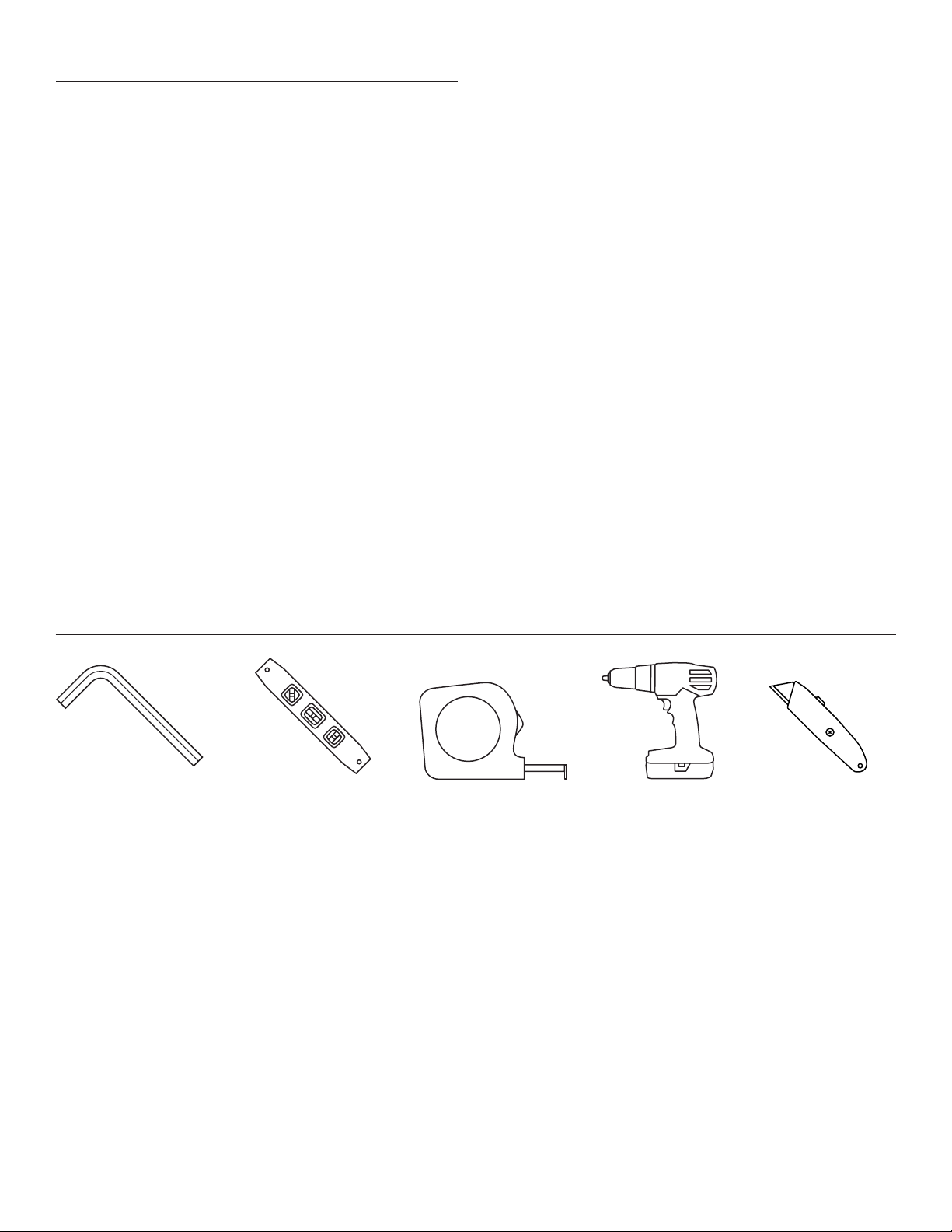
Tools Required for Installation
1/8" and 5/64"
Allen Wrenchs
Carpenter's Level
Tape Measure
Electric Screw Gun Utility Knife
2
Page 3
Unpackaging the Frame:
1. The frame will arrive in two separate cardboard boxes. One
box will be very long and will house the top & bottom pieces.
The smaller cardboard box will house the side frame pieces,
hanger hardware, hardware required to put frame together
and the wall switch.
2. To open the boxes there is a side lap that is taped down the
length of the box. It will be labeled OPEN THIS SIDE (Figure 1).
Carefully cut tape down the length of the box with a utility
knife and fold box open. You will have to tear hard on the
ends as it is stapled on the ends.
Frame Assembly
3. Inside each box the frame pieces will be individually paper
wrapped and taped. Remove all paper from pieces.
CAUTION: DO NOT USE A UTILITY KNIFE TO REMOVE
PAPER FROM PIECES
ATTENTION: N'UTILISEZ PAS DE COUTEAU UTILITAIRE
POUR RETIRER LE PAPIER DES PIÈCES.
4. Remove all paper and styrofoam blocks from top frame
assembly after unwrapping.
1. In the hardware bag, you will receive (12) #10 x .375" long hex
button head screws and (4) #10 x .500" long hex button head
screws required for frame assembly.
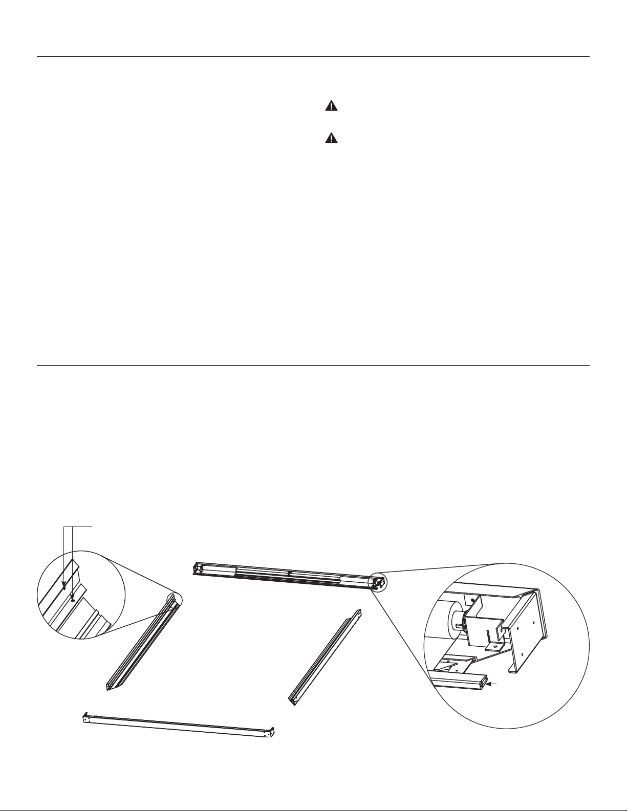
2. Lay frame pieces out on loor or table as shown in Figure 1.
The top frame assembly has the roller and motor assembly
attached to it. The side frames are the two shorter pieces.
Watch side piece to make sure oriented properly. The sides
have two riv nuts used for roller mounting brackets that
should face toward the top frame piece.
Rivnut
Top of Frame
Left of
Frame
Right of
Frame
Bottom of Frame
Make sure slat is
guided in to the
channel
Figure 1
3
Page 4
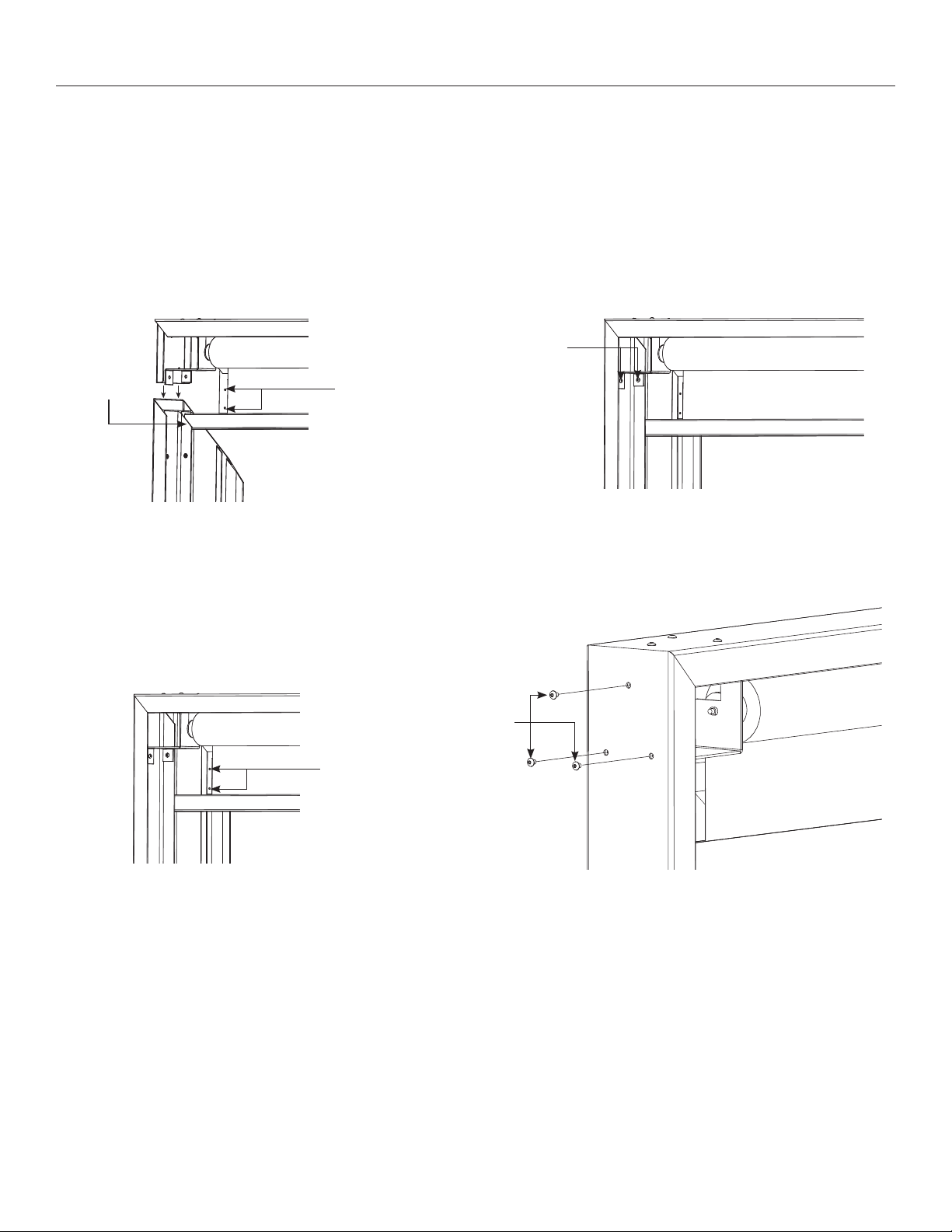
Frame Assembly (continued)
3. Assemble left side of frame to the top of frame. The large
black metal L bracket will slide into the aluminum extrusion
while the small L bracket will slide into the aluminum channel.
The pin end bracket needs to be on the outer surface to bolt
into the rivnuts of the left side piece. The slat will need to be
guided in between the standing in and the front of the frame.
Guide slat in
front of in
Figure 2 – Back of Frame
Loosen set
screws for
clearence
before
inserting
side pieces.
4. Using a 5/64" allen wrench, tighten set screws in frame
straightner bracket. Adjust set screw so that the front surfaces
evenly match at the corner (Figure 4).
5. Using a 1/8" allen wrench, insert (3) #10 x .375" long button head
screws in frame corner connector bracket. Tighten down snug to
frame surface (Figure 5).
Fasten pin
end bracket
(2) #10 x .500"
Figure 3 – Back of Frame
Figure 4 – Back of Frame
Button
Head
Screws
Set Screws
Figure 5
4
Page 5

Frame Assembly (continued)
6. Assemble right side of frame to the top of frame. This is done
exactly the same way as the left side. When assembling the
unit, route the motor wire behind bracket as shown and
attach ield wiring box to side of frame (Figure 6 and 7).
7. Assemble bottom of frame to the right and left sections of
frame. This is done by sliding the large black metal L brackets
into the aluminum extrusion while the small L brackets will
slide in the aluminum channels. Then repeat steps 8 and 9 on
each side (Figure 8).
Route motor
wire behind
bracket
Motor
Ground
Screw
(2) 1/420 x .375"
screws atiach box
to frame
Installation Hole
For 1/2" Conduit
Figure 6 – Back of Frame Figure 7 – Back of Frame
Incoming Wire
Grounding Lug
Figure 8
5
Page 6

Wall Mounting Assembly
1. Depending on size of screen it will be shipped with either 2
wall brackets that are 48" long or 2 wall brackets that are 64"
long. Two small L brackets included will be used to hold
frame securley to wall at bottom.
2. To install the Dual Format lmager over a Da-Lite Perm-Wall
screen you will need to place the supplied wooden spacers
between the screen and the wall.
NOTE: Da-Snap, lmager and Cinema Contour frames do not
require any spacers.
3. Refer to Figure 9 hanger bracket location. Dimension A will
vary depending on the type of screen you have. Dimension A
is measured from the top of the screen frame to the top of
the hanger bracket.
Screen Type Dimension A
Cinema Contour 33/4"
Perm-Wall 43/4"
lmager 43/4"
Da-Snap 51/4"
A
Figure 9
4. Both wall brackets must be mounted into at least two wall
studs. Check to make sure both brackets are vertically level
with each other.
5. Drill holes and attach mounting brackets into wall. You will
need at least 4" clearance above the drilled holes to hang the
screen. Dimension for hole is shown from the top bracket to
center hole position. It is recommended to use a ¼" x 1 ½" lag
screw (not supplied) to fasten bracket to wall.
1 ½"
Figure 10
6
Page 7

Wall Mounting Assembly (continued)
6. Hang the frame assembly on the hanger brackets as shown
in image. Carefully slide bracket between the top of the frame
extrusion and the roller assembly. There is a lip on the back
of the frame that wedges itself into the hanger bracket once
fully installed on bracket. This is a two person installation. Do
not attempt to do this without two people.
The top of the frame assembly will be approximately 1 ¾" above
the hanger brackets when mounted.
Slide frame
over brackets
Bracket
Figure 11
Figure 12
Back lip of frame will
wedge down between
wall bracket and wall
Figure 13
7
Page 8

120V Wiring Diagram for Standard Wall Switch
NOTE: Junction box located on left upper side of frame
Note: A single switch cannot be used to operate more than one
screen. Contact Da-Lite for further information.
White
Black
Red
Green
Motor
UP
OFF
DOWN
White
Black (Up)
Red (Down)
AC Common
Red
AC Hot 120VAC 60Hz 1 Amp
Black
SPOT Switch
with Center Of
CAUTION: This switch
can not be used with LVC.
ATTENTION: Ce commutateur ne peut être
utilisé avec le tableau de contrôle basse
tension.
Black/Yellow
8
Page 9

Post Installation Procedures Travel Adjustments:
1. Test installation by carefully running mask surface up and
down 23 times. Be prepared to stop screen. Standard Duty
Cycle: 1 MIN. ON I 3 MIN. OFF.
CAUTION! Excessive countinous operation may cause
overheating. If motor overheats put switch in center-of
position and allow motor to cool for 30 minutes.
ATTENTION! Le fonctionnement continu et excessif peut
provoquer une surchaufe. Si le moteur surchaufe, mettez
le commutateur au centre sur la position Of et laissez le
moteur refroidir pendant 30 minutes.
Masking travel is stopped automatically in the up and down
positions by limit switches that are properly adjusted at the
factory. Should it be necessary to adjust the stop positions,
proceed in the following manner:
NOTE: Use a screw driver or 5/32" Allen wrench to make
adjustments.
MORE SCREEN DROP
1 . Place operating switch in "down" position.
2. When the mask stops, turn the "down" limit knob (WHITE) one
turn counterclockwise. Test by raising the mask
approximately two feet, then lower again. Repeat until desired
picture surface position is attained.
LESS SCREEN DROP
1. Raise picture surface approximately two feet above
desired level.
2. Place operating switch in "of" position.
3. Turn the "down" limit knob (WHITE) one turn clockwise. Test
by raising the mask approximately two feet, then lower again.
Repeat until desired picture surface position in attained.
9
Page 10

Troubleshooting
Symptom Cause Solution
Masking System will not
operate. Motor does not hum.
Screen will not operate
and motor does not hum.
Power at junction box.
Incorrect line voltage.
Blown fuse. Replace fuse.
Tripped circuit breaker. Reset circuit breaker.
No power to operating switch
or junction.
Thermal overload tripped. Let motor cool down for 15 minutes. Try again.
Broken wire in the “down” or “up” position. Check for continuity. Cut o old splice and reconnect.
Defective motor, limit switch or capacitor. Replace motor assembly. NOTE: Motor is a sealed assembly.
Capacitor burned out. Replace motor assembly.
Verify 115125V (or 220240V). If insuicient voltage, rewire
incoming electric line.
Check above. Tighten all loose wire connections. Correct any
improper connections.
Down Position
Check for power across black and white leads.
Up Position
Check for power across red and white leads.
Masking System does not stop
at correct position.
Noise.
NOTE: Masking System will
operate with a low-pitched
hum.
Coasting. Defective brake. Replace motor assembly.
Mask hangs crooked.
Limit switch is out of adjustment. See Mask Travel Adjustment section on page 9.
Squeaking, rubber end plug rubbing on motor. Center roller in case.
Grinding. Foreign object in screen rubbing on roller
or fabric.
Gear noise. Replace motor assembly.
Masking System not installed properly. Check for level and plumb.
Mask has backed up inside case.
Mask is damaged. Replace mask.
Remove.
Adjust "down" limit switch slowly until roller is exposed and
wrinkle comes out, then readjust for proper drop.
10
Page 11

11
Page 12

LIMITED ONE YEAR WARRANTY ON DALITE PRESENTATION PRODUCTS
Milestone AV Technologies LLC warrants certain Da-Lite branded products to the original purchaser only, to be free from defects in
materials and workmanship for a period of one (1) year from the date of purchase by the original purchaser; provided they are properly
operated according to Da-Lite's instructions and are not damaged due to improper handling or treatment after shipment from the
factory.
This warranty does not apply to equipment showing evidence of misuse, abuse or accidental damage, or which has been tampered
with or repaired by a person other than authorized Da-Lite personnel.
Da-Lite’s sole obligation under this warranty shall be to repair or to replace (at Da-Lite’s option) the defective part of the merchandise.
Returns for service should be made to your Da-Lite dealer. If it is necessary for the dealer to return the screen or part to Da-Lite,
transportation expenses to and from Da-Lite are payable by the purchaser and Da-Lite is not responsible for damage in shipment.
To protect yourself against damage or loss in transit, insure the product and prepay all transportation expenses.
TO THE MAXIMUM EXTENT PERMITTED BY APPLICABLE LAW, THIS WARRANTY IS IN LIEU OF ALL OTHER WARRANTIES, EXPRESS
OR IMPLIED, INCLUDING WARRANTIES AS TO FITNESS FOR USE AND MERCHANTABILITY. Any implied warranties of itness for use,
or merchantability, that may be mandated by statute or rule of law are limited to the one (1) year warranty period. This warranty gives
you speciic legal rights, and you may also have other rights, which vary from state-to-state. TO THE MAXIMUM EXTENT PERMITTED
BY APPLICABLE LAW, NO LIABILITY IS ASSUMED FOR EXPENSES OR DAMAGES RESULTING FROM INTERRUPTION IN OPERATION
OF EQUIPMENT, OR FOR INCIDENTAL, DIRECT, OR CONSEQUENTIAL DAMAGES OF ANY NATURE.
In the event that there is a defect in materials or workmanship of a Da-Lite product, you may contact our Sales Partners at PO Box 137,
Warsaw, IN 465810137, (574) 2678101, (800) 6223737.
IMPORTANT: THIS WARRANTY SHALL NOT BE VALID AND DALITE BRANDED PRODUCTS SHALL NOT BE BOUND BY THIS
WARRANTY IF THE PRODUCT IS NOT OPERATED IN ACCORDANCE WITH THE DALITE WRITTEN INSTRUCTIONS.
Keep your sales receipt to prove the date of purchase and your original ownership.
A Milestone AV Technologies Brand
3100 North Detroit Street
Warsaw, Indiana 46582
P: 574.267.8101 or 800.622.3737
F: 574.267.7804 or 877.325.4832
E: info@da-lite.com
www.da-lite.com
DL–0293 (Rev. 2) 09.14
© 2014 Milestone AV Technologies LLC. Printed in U.S.A.
37865
 Loading...