

Page 1
76488 Rev. 7/02Printed in U.S.A.
MAINTENANCE
PROJECTION SCREEN MAINTENANCE
Protect your screen by keeping it rolled in its
case when not in use. Always examine both
front and back of surface before rerolling into
case to make certain screen is free of dust, dirt
or other foreign matter. Use a very soft duster
brush to gently remove foreign particles.
CASE MAINTENANCE
The case of the screen has a Resistovar finish.
This finish is resistant against: water, alcohol,
marring, scratching, and nail polish remover. To
help maintain the best appearance of the case
it is recommended that the case be polished
with any reputable liquid or paste wax polish.
An oil type polish is not recommended because
it allows for the collection of dust and finger
prints. When necessary, this finish may be
wiped with a damp soft cloth using a mild soap
solution, rinsed with clear water and dried with
a soft cloth.
POWER
PRESENTATION PRODUCTS
The
In
Operating Instructions
For
Designer
Manual Screen
DA-LITE SCREEN COMPANY, INC.
3100 North Detroit Street
Post Office Box 137
Warsaw, Indiana 46581-0137
Phone: 574/267-8101
800-622-3737
Fax: 574/267-7804
http:// www.da-lite.com
e-mail: info@da-lite.com
Page 2
FOR WALL MOUNTING
HARDWARE PROVIDED
2 – “V” Bars ( one is factory mounted to the
back of the case; one will be mounted to
the wall)
6 – Toggle Bolts, 4"
6 – Lead Shields, #10-14 x 11/2"
6 – Phillips Flat Head Wood Screws, #10 x 2"
TOOLS REQUIRED
Electric Drill
Masonry Bit 5/16" (if mounting in solid masonry
or concrete)
Screw Driver, #2 Flat Tip (if using toggle bolts)
or #2 Phillips (if mounting in solid masonry or
concrete)
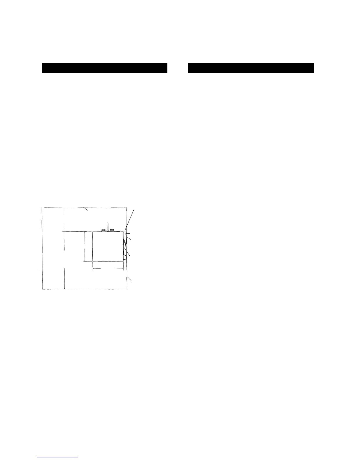
INSTALLATION INSTRUCTIONS
Determine the height of the top of the case
from the floor. This will be the height of the
wall mounted “V” bar.
Hold the loose “V” bar to the wall at the height
determined above (MAKE SURE IT IS LEVEL),
and mark the location for the screw holes. To
mount the “V” bar on solid concrete or
masonry wall, drill 5/16" holes and insert the lead
shields. Fasten the “V” bar to the wall using
the #10 x 2" wood screws. If you are mounting
to a hollow wall, drill 1/2" holes and insert the
toggle bolts. Then fasten the “V” bar to the
wall with the toggle bolts. Now set the case in
place on the wall with the “V” bar of the case
nestled into the “V” bar on the wall.
FOR CEILING SUSPENSION
Position and properly anchor screw hooks into
ceiling, beam or other solid surface. Then
proceed to use the two “D” rings that are
factory mounted to the top of the case to hang
the case securely.
TO LOWER AND RAISE PICTURE SURFACE
To lower the picture surface, pull the screen
down all the way. Then hesitate and allow the
screen to retract very slowly until it locks in
place. To raise the picture surface pull down on
the pull bail, then raise quickly, as a window
shade. Keep control of the picture surface. Do
not allow it to roll uncontrolled into the case or
damage to the screen is sure to result.
Allow a minimum of
1
1
/4" from the ceiling
Ceiling
4
1
/4"
4"
Determine
measurement to the
top of the Case
Wall
“V” Bar mounted
to the back of the
Case at the factory
“V” Bar mounted
to the wall
Mount top of
“V” Bar flush
with top of Case
Floor line
 Loading...