

Page 1
INSTRUCTION BOOK FOR
Series 200 And 300
Lace And Grommet Frame
Page 2

Installation
Frame Assembly
You will need a 9/16" wrench to assemble your Series 200/300 lace and grommet frame. If you have a split frame, you will also need a
3/16" allen wrench. Before beginning assembly make sure the work surface is clear of objects or debris that could scratch the frame or
puncture the viewing surface. Use the wrapping material to lay the frame sections on to keep from scratching the frame.
1. Unwrap the frame sections and orient them as shown in the
Figure below. Note that the ends are color coded. Make sure
the colors match at each corner. If your frame has the
optional Pro-Trim masked borders, lay the frame with the
borders facing down. Be sure to lay the frame on the
wrapping material to keep the Pro-Trim clean.
2. If your frame has two-piece top and bottom frame sections,
match the color codes on the ends of the tubes. See split
frame assembly on page 4. When top and bottom sections
are assembled the corners should lay lat to assure that
the unit does not twist or bow.
3. Slide the side frame sections onto the top frame section.
Insert one 3/8" bolt at each corner and tighten (do not
over-tighten).
4. The next step is much easier with two people. With one
person at each end, slide the bottom frame section into the
side frame sections. Make sure each side slides evenly to
avoid binding. Insert one 3/8" bolt at each corner and tighten
(do not over-tighten).
5. Frame assembly is complete. Next, unwrap the viewing
surface (sold separately) and lay it face down inside
the frame assembly.
6. The viewing side of the surface is wrapped to the inside
of the roll so you will have to unroll the surface and then
turn it over. Be sure to lay the surface on the wrapping
material to keep it clean.
7. Start at one side of the frame and locate the center of the
viewing surface and frame. The center of the screen surface
can be identiied by a bright colored grommet on each of the
four sides. The center of the frame is marked by a piece of
colored tape. Starting at the center, begin attaching the hooks
on the frame into the grommets holes in the screen surface.
When you get to one end, the grommet in the corner of the
viewing surface should be attached to the s-hook in the
corner of the frame.
3/8" Bolt
4Pieces
Figure 1
2
Page 3
Series 200 Installation
The Series 200 frame is supplied with eyebolts for ceiling installations and hanger brackets for wall mount installations.
Ceiling Installation: The frame is predrilled for the attachment
of the eyebolts. There are 3 eyebolts for smaller frames with a
one-piece top frame rail. Larger frames with two-piece top frame
rails will have 4 eyebolts. Insert the eyebolts through the frame
and attach the hex nut to the eyebolt.
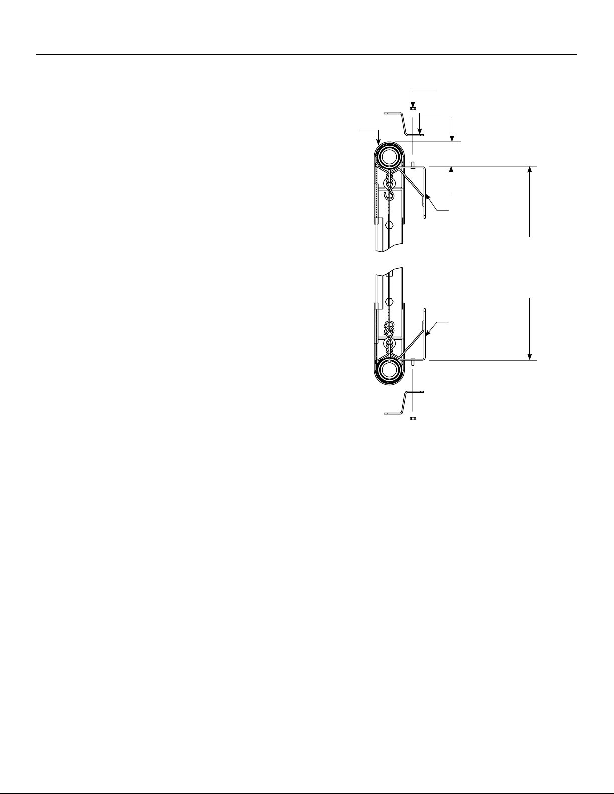
Wall Mount Installation: There are 6 hanger brackets for
smaller frames with a one-piece top frame rail. 8 hanger brackets
are provided for larger frames with two-piece top frame rails.
Determine where the Series 200 frame will be mounted on the
wall. Consider the following before attaching the hanger
brackets to the wall.
• The hanger brackets must be anchored to a supported
section of the wall, such as a wall stud.
• The hanger brackets should be spaced on the wall
so they line up with the S-hooks on the frame. This
will prevent the lace cord from being pinched between
the frame and hanger.
• You will need at least 2" above the hanger bracket
to mount the Series 200 frame (see Figure 2).
• Frames with one-piece top frame rails should be
supported at the center of the frame and about
24 feet from each end of the frame.
• Frames with two-piece top frame rails should be
supported about 23 feet on each side of the center
joint and about 24 feet from each end of the frame.
Series
200
Frame
Hex Nut
Frame Clamp
2" Minimum
Upper Hanger
Bracket
Equals Outside Frame Height
• 3 ¾" With Pro-Trim Border
• 3 ½" Without Pro-Trim Border
(Pro-Trim Border Adds ¼"
To Frame Height
Lower Hanger
Bracket
Figure 2
1. Attach 3 or 4 hanger brackets (as required above) at the
same height along the wall. To determine the distance
between the upper and lower hanger brackets you must
measure the overall height of the frame. If your frame has the
Pro-Trim border subtract 33/4" from the overall height. If your
frame does not have the Pro-Trim border subtract 31/2" from
the overall height. Using this number, measure down from
each hanger bracket and mark the wall.
2. Line up the lower hanger bracket with the mark and secure
it to the wall. Refer to Figure 2.
3. Remove the frame clamp from the hanger brackets and
position the Series 200 frame on the hanger brackets as
shown in Figure 2.
4. Place the frame clamp onto the hanger bracket and
secure it with the supplied hex nut.
3
Page 4

Series 300 Installation
The Series 300 frame is supplied with eyebolts for ceiling installations and hanger brackets for wall mount installations.
Ceiling Installation: The frame is predrilled for the attachment
of the eyebolts. There are 3 eyebolts for smaller frames with a
one-piece top frame rail. Larger frames with two-piece top frame
rails will have 4 eyebolts. Insert the eyebolts through the frame
and attach the hex nut to the eyebolt.
Wall Mount Installation: There are 6 hanger brackets for
smaller frames with a one-piece top frame rail. 8 hanger brackets
are provided for larger frames with two-piece top frame rails.
Determine where the Series 300 frame will be mounted on the
wall. Consider the following before attaching the hanger brackets
to the wall.
• The hanger brackets must be anchored to a supported
section of the wall, such as a wall stud.
• The hanger brackets should be spaced on the wall so
they line up with the S-hooks on the frame. This will
prevent the lace cord from being pinched between the
frame and hanger.
• You will need at least 3" above the hanger bracket to
mount the Series 300 frame (see Figure 3).
• Frames with one-piece top frame rails should be
supported at the center of the frame and about 24 feet
from each end of the frame.
• Frames with two-piece top frame rails should be
supported about 23 feet on each side of the center joint
and about 24 feet from each end of the frame.
Series
300
Frame
Hex Nut
Frame Clamp
3" Minimum
Upper Hanger
Bracket
Equals Outside Frame Height
• 4 ¾" With Pro-Trim Border
• 4 ½" Without Pro-Trim Border
(Pro-Trim Border Adds ¼"
To Frame Height
Lower Hanger
Bracket
Figure 3
1. Attach 3 or 4 hanger brackets (as required above) at the
same height along the wall. To determine the distance
between the upper and lower hanger brackets you must
measure the overall height of the frame. If your frame has the
Pro-Trim border subtract 43/4" from the overall height. If your
frame does not have the Pro-Trim border subtract 41/2" from
the overall height. Using this number, measure down from
each hanger bracket and mark the wall.
2. Line up the lower hanger bracket with the mark and secure it
to the wall. Refer to Figure 3.
3. Remove the frame clamp from the hanger brackets and
position the Series 300 frame on the hanger brackets as
shown in Figure 3.
4. Place the frame clamp onto the hanger bracket and secure it
with the supplied hex nut.
4
Page 5

Split Frame Assembly
1. Loosely tighten set screw so that pieces will still move
freely. See Figure 4.
2. Slide tube over connector and line up hole. See Figure 5.
3. Insert second set screw and tighten all the way until tube
is secure. See Figure 6.
Figure 4
Figure 6
4. Tighten irst set screw the rest of the way. See Figure 6.
5. Finished joint should look like Figure 7.
Figure 5
Figure 7
Page 6

Page 7

Page 8

LIMITED ONE YEAR WARRANTY ON DA-LITE PRESENTATION PRODUCTS
Milestone AV Technologies LLC warrants certain Da-Lite branded products to the original purchaser only, to be free from defects in
materials and workmanship for a period of one (1) year from the date of purchase by the original purchaser; provided they are properly
operated according to Da-Lite's instructions and are not damaged due to improper handling or treatment after shipment from the
factory.
This warranty does not apply to equipment showing evidence of misuse, abuse or accidental damage, or which has been tampered
with or repaired by a person other than authorized Da-Lite personnel.
Da-Lite’s sole obligation under this warranty shall be to repair or to replace (at Da-Lite’s option) the defective part of the merchandise.
Returns for service should be made to your Da-Lite dealer. If it is necessary for the dealer to return the screen or part to Da-Lite,
transportation expenses to and from Da-Lite are payable by the purchaser and Da-Lite is not responsible for damage in shipment.
To protect yourself against damage or loss in transit, insure the product and prepay all transportation expenses.
TO THE MAXIMUM EXTENT PERMITTED BY APPLICABLE LAW, THIS WARRANTY IS IN LIEU OF ALL OTHER WARRANTIES, EXPRESS
OR IMPLIED, INCLUDING WARRANTIES AS TO FITNESS FOR USE AND MERCHANTABILITY. Any implied warranties of itness for use,
or merchantability, that may be mandated by statute or rule of law are limited to the one (1) year warranty period. This warranty gives
you speciic legal rights, and you may also have other rights, which vary from state-to-state. TO THE MAXIMUM EXTENT PERMITTED
BY APPLICABLE LAW, NO LIABILITY IS ASSUMED FOR EXPENSES OR DAMAGES RESULTING FROM INTERRUPTION IN OPERATION
OF EQUIPMENT, OR FOR INCIDENTAL, DIRECT, OR CONSEQUENTIAL DAMAGES OF ANY NATURE.
In the event that there is a defect in materials or workmanship of a Da-Lite product, you may contact our Sales Partners at PO Box 137,
Warsaw, IN 465810137, (574) 2678101, (800) 6223737.
IMPORTANT: THIS WARRANTY SHALL NOT BE VALID AND DA-LITE BRANDED PRODUCTS SHALL NOT BE BOUND BY THIS
WARRANTY IF THE PRODUCT IS NOT OPERATED IN ACCORDANCE WITH THE DA-LITE WRITTEN INSTRUCTIONS.
Keep your sales receipt to prove the date of purchase and your original ownership.
A Milestone AV Technologies Brand
3100 North Detroit Street
Warsaw, Indiana 46582
P: 574.267.8101 or 800.622.3737
F: 574.267.7804 or 877.325.4832
E: info@da-lite.com
www.da-lite.com
DL–0286 01.14
© 2013 Milestone AV Technologies LLC. Printed in U.S.A.
94696
 Loading...