

Page 1
INSTRUCTION BOOK FOR
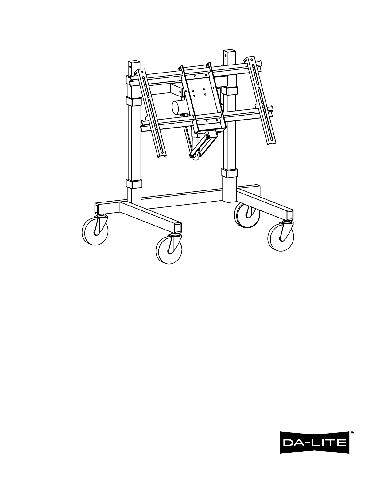
Mobile Plasma Stand Automated
Conidence Monitor MPSACM
Page 2
Mobile Plasma Stand Automated Conidence Monitor MPSACM
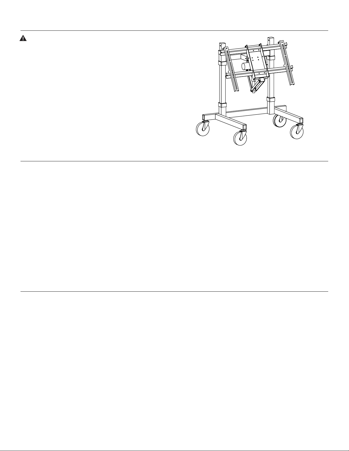
CAUTION: The user of this product should exercise caution
when moving the Mobile Plasma Stand. Any sudden stop could
cause instability of the stand and could cause serious injury and/
or damage. The stand should always be pushed, never pulled, by
the user. Always push from the side of the stand, never from the
front or back of the stand.
Important Safety Instructions
When using your video equipment, basic safety precautions should always be followed, including the following:
1. Read and understand all instructions before using.
2. Position the cord so that it will not be tripped over, pulled, or
contact hot surfaces.
3. If an extension cord is necessary, a cord with a current rating at
least equal to that of the appliance should be used. Cords rated
for less amperage than the appliance may overheat.
4. To reduce the risk of electric shock, do not disassemble this
appliance. Contact an authorized service dealer when repair
work is required. Incorrect reassembly can cause electric shock
when the appliance is used subsequently.
5. The use of an accessory attachment not recommended by the
Procedure
1. Remove contents from carton and examine for damaged or missing parts.
Required Tools:
- 7/16” wrench
- 9/16" wrench
- 3/16” allen wrench
manufacturer may cause a risk of ire, electric shock, or injury to
persons.
Save These Instructions
- Phillips screwdriver
2
Page 3
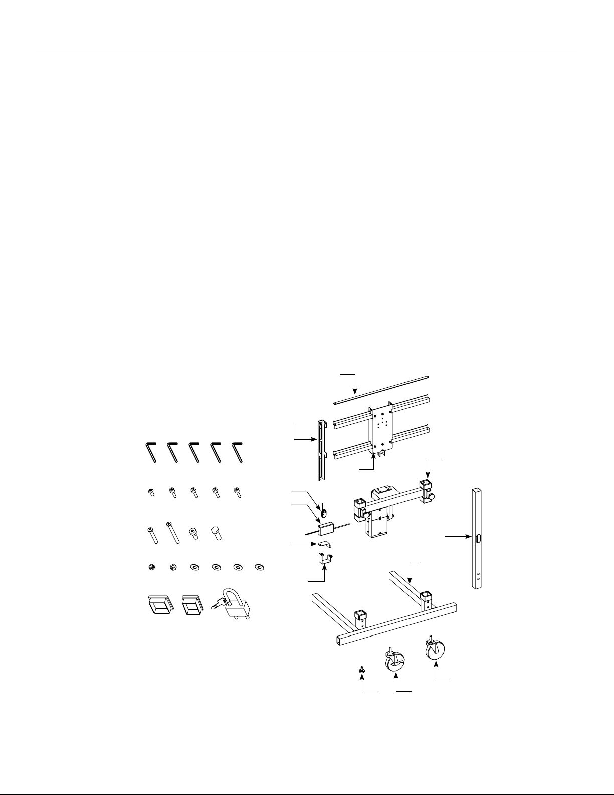
Included Parts
Item Description QTY
1 Security Bar 1
2 Hanging Bracket 2
3 Zee-Bar Plate Ass'y 1
4 Key FOB Remote, RF 1
5 Power Supply 1
6 Power Supply Bracket, Small 1
7 Power Supply Bracket, Large 1
8 Top Assembly 1
9 Column 2
10 Base Assembly 1
11 Glide, Furniture 2
12 Caster .5" W/ Brake 2
13 Caster .5" 4
Package Set 1
A End Closure, 11/2" x 2" 4
B End Closure, 13/4", Square 2
C Nut, Hex 1/4"-20 KEPS 4
D Screw, BHSCS 1/4"-20 x 1/2" 6
E Screw, Mach 1/4"-20 x 2" 2
F Screw, Shoulder 3/8 x 3/8" 2
G Screw, HHCS 3/8"-16 x 1" 4
Item Description QTY
H Wrench, Allen 5/32" 1
Package Set 1
J Padlock W/ Keys 1
Package Set 1
K Screw, SHCS M8 x 20mm 4
L Washer, Flat 3/8" 4
M Wrench, Allen 6mm 1
Package Set 1
N Screw, SHCS M6 x 20mm 4
P Washer, Flat 1/4" 4
Q Wrench, Allen 5mm 1
Package Set 1
R Screw, SHCS M5 x 20mm 4
S Screw, SHCS M4 x 12mm 4
T Washer, Flat #10 4
U Washer, Flat #8 4
V Wrench, Allen 4mm 1
W Wrench, Allen 3mm 1
Package Set 1
X Screw, Mach 1/4"-20 x 21/2" 1
Y Nut, Hex 1/4"-20 Nylon Lock 1
C Nut, Hex 1/4"-20 Keps 1
H M Q V W
D K N R S
E X F G
Y C L P T U
B A J
1
2
8
3
4
5
6
9
10
7
13
11
3
12
Page 4

Procedure (Continued)
2. Insert the Caster stems or Glide stems into the Base.
See Figure 1. Must go in straight.
A
13
11
Figure 1
3. Insert tube enclosures shown.
4. Insert two Columns into the Base and install the fasteners
shown. Leave loose at this time.
5. Slide the Top Assembly down the Columns. See Figure 2.
Position the Top by tightening both Knobs. Make sure unit
is level.
12
G
6. Tighten the fasteners at the bottom of the Columns.
7. Attach Zee-Bar Plate to Hinge. See Figure 3.
Hinge
D
F
Link
C
Figure 3
8. Attach the Links to the outside of the Zee Bar Assembly.
9. Mount the Hanging Brackets to the back of the Plasma Unit
utilizing all the fastener points recommended by the plasma
manufacturer. See Figure 4.
Knobs To Hold
Position
Figure 2
Hanging
Bracket
Figure 4
Plasma Unit
4
Page 5

Procedure (Continued)
10. Hang the plasma unit on the Zee-Bars making sure the top and
bottom notches on each Hanging Bracket are placed over the
upper and lower Zee-Bars. See Figure 5.
11. Slide the Security Bar through the slots in the Hanging Brackets,
bolt one end to the Zee-Bar then secure the opposite end with
the pad lock. See Figure 5 & 6.
Plasma
(Not Included)
See
Fig.6
J
Figure 5
X
Security Bar
12. Install Power Supply. See Figure 7.
Figure 7
E
13. Plug electrical cord into power supply.
14. Connect power plug into power jack on the side of the
electrical housing.
15. A remote control is included in the carton of the power supply.
Use the remote control or rocker switch on the side of the
electrical housing to operate the tilt as needed.
16. The small red button on the remote is for “stop” but is not
needed. The conidence monitor will stop with the release of
either the “up” or “down” button. See Figure 8. The rocker switch
will operate the conidence monitor in the same manner.
Figure 6
C
Y
Zee Bar
17. Install tube enclosures. See Figure 9.
18. Install fasteners into top of Columns for theft deterrent.
Figure 8
B
D
Figure 9
Page 6

6
Page 7

7
Page 8

A Milestone AV Technologies Brand
3100 North Detroit Street
Warsaw, Indiana 46582
P: 574.267.8101 or 800.622.3737
F: 574.267.7804 or 877.325.4832
E: info@da-lite.com
www.da-lite.com
DL–0381 (Rev. 1) 02.15
© 2015 Milestone AV Technologies LLC. Printed in U.S.A.
E-443
 Loading...