

Page 1
DA-LITE SCREEN COMPANY, INC.
3100 North Detroit Street
Post Office Box 137
Warsaw, Indiana 46581-0137
Phone: 574-267-8101
800-622-3737
Fax: 574-267-7804
Toll Free Fax: 877-325-4832
www.da-lite.com
e-mail: info@da-lite.com
POWER
PRESENTATION PRODUCTS
The
In
Installation Instructions for
VIDEO PROJECTOR INTERFACE
Page 2
CAUTION: THE PROJECTOR MUST BE TURNED OFF BEFORE CONNECTING THE TRIGGER WIRES TO THE PROJECTOR. FAILURE
TO DO SO MAY DAMAGE THE CONTROLLER.
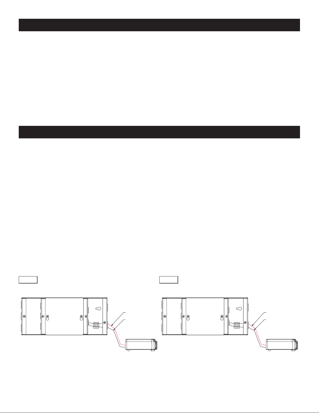
1. Use 2-conductor 20-24 gauge wire to extend the low voltage connection from the projector’s 5 or 12-volt screen
trigger output to the length required to reach the VPI. When extending the low voltage connection from the
projector’s screen trigger output, be sure to maintain the proper polarity. the red wire from the VPI is the “signal”
and the black wire from the VPI is the “ground”.
2. Connect the wires from the VPI that are labeled “Low Voltage Connection” to the end of the extended screen
trigger wires above. See Figure 1.
CAUTION: NEVER APPLY VOLTAGE TO THE PROJECTOR’S SCREEN TRIGGER WIRES OR THE VPI AND/OR PROJECTOR WILL BE
DAMAGED.
VIDEO PROJECTOR INTERFACE INSTALLATION
1
The Video Projector Interface (VPI) housing is divided into three compartments. The compartment labeled “Low Voltage
Connections” is where you will connect the VPI to the projector’s output. The compartment labeled “AC Power
Connections” is where the main power, motor and wall switch wire connections are made. Access is not required to the
center compartment.
WARNING: TO PREVENT ELECTRICAL SHOCK OR DAMAGE TO THE VIDEO PROJECTOR INTERFACE (VPI), DO NOT APPLY
POWER TO THE VPI UNTIL ALL CONNECTIONS ARE COMPLETE. MAKE SURE POWER IS TURNED OFF ON ALL CIRCUITS
BEFORE MAKING CONNECTIONS.
CAUTION: ANY ITEM BEING CONNECTED TO THE VPI CANNOT BE ENERGIZED. DO NOT HAVE POWER CONNECTED TO THE
SWITCH BEFORE ALL CONNECTIONS ARE MADE.
▲
!
LOW VOLTAGE CONNECTION
RED (SIG)(+)
BLACK (GRD)(-)
RED (SIG)(+)
BLACK (GRD)(-)
5/12 VOLT SCREEN
TRIGGER ON
PROJECTOR
5/12 VOLT SCREEN
TRIGGER ON
PROJECTOR
RECOMMENDED WIRE SIZE: 14-18 AWG RECOMMENDED WIRE SIZE: 14-18 AWG
FIGURE 1
120V 240V
▲
!
▲
!
▲
!
Page 3
2
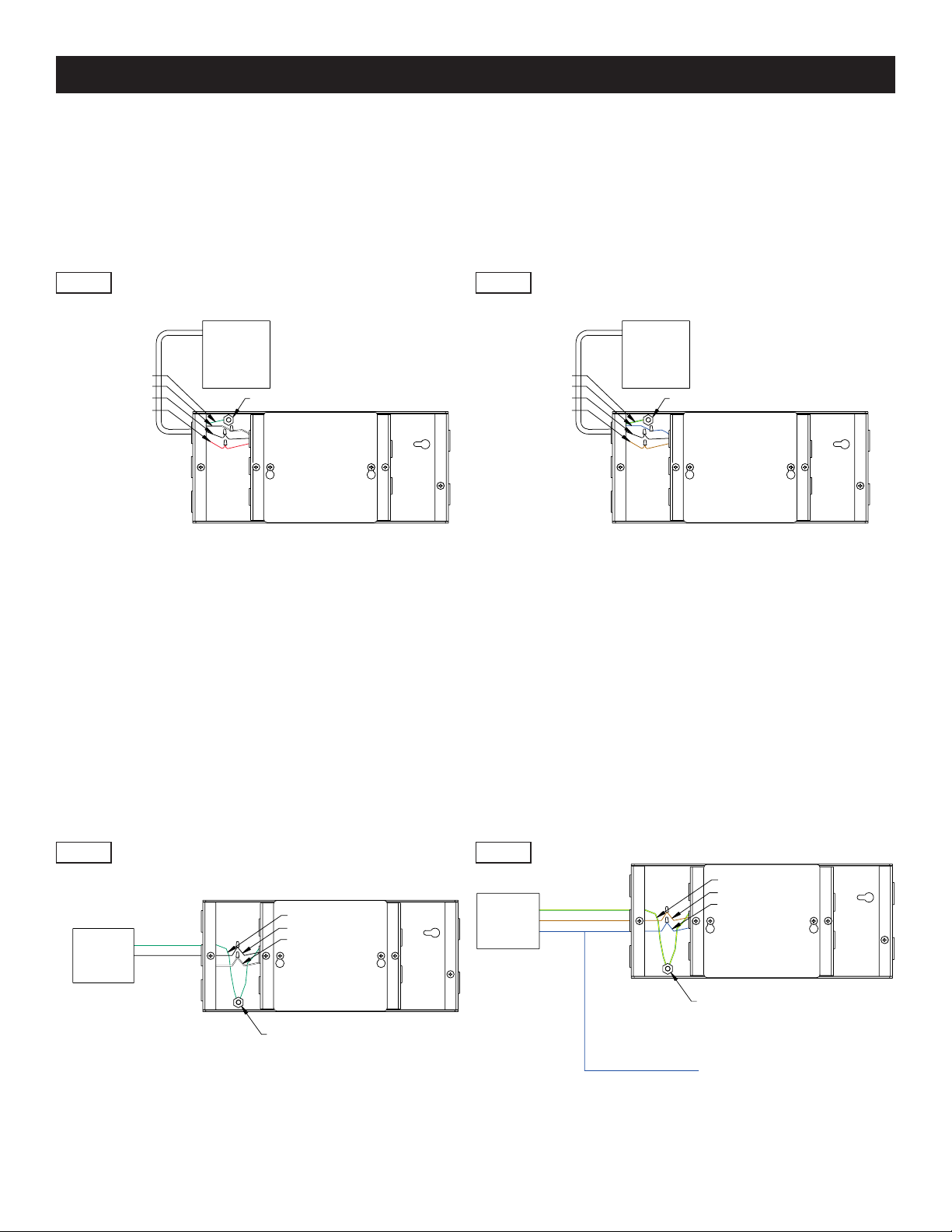
Screen Motor
1. Using 4-conductor, 14-18 gauge wire, extend the motor wires from the screen junction box to the length required
to reach the VPI.
2. Connect the extended wires from the screen motor to the VPI wires that are labeled “motor wires”. Refer to
Figure 2.
AC POWER CONNECTIONS
GREEN
WWHHIITTEE
BLACK
RED
GROUND LUG
FIGURE 2
POWER
SOURCE
120VAC
60HZ
GREEN (GROUND)
BLACK (HOT)
WWHHIITTEE (COMMON)
GROUND LUG
FIGURE 3
AC Power Source
1. Connect the incoming power wires to the VPI wires that are labeled “AC power input”.
2. Connect the building ground wire to the ground lug on the metal housing. Refer to Figure 3.
RECOMMENDED WIRE SIZE: 14-18 AWG
SCREEN
MOTOR
YELLOW/GREEN
BLUE
BLACK
BROWN
GROUND LUG
RECOMMENDED WIRE SIZE: 14-18 AWG
SCREEN
MOTOR
GREEN (GROUND)
BLACK (HOT)
WWHHII TTEE (COMMON)
RECOMMENDED WIRE SIZE: 14-18 AWG
POWER
SOURCE
220VAC
50HZ
YELLOW/GREEN (GROUND)
BROWN (HOT)
BLUE (COMMON)
GROUND LUG
YELLOW/GREEN (GROUND)
BROWN (HOT)
BLUE (COMMON)
RECOMMENDED WIRE SIZE: 14-18 AWG
120V 240V
120V 240V
BLUE-COMMON
TO WALL SWITCH
Page 4
3
Printed in U.S.A. 93841 Rev. 5/08
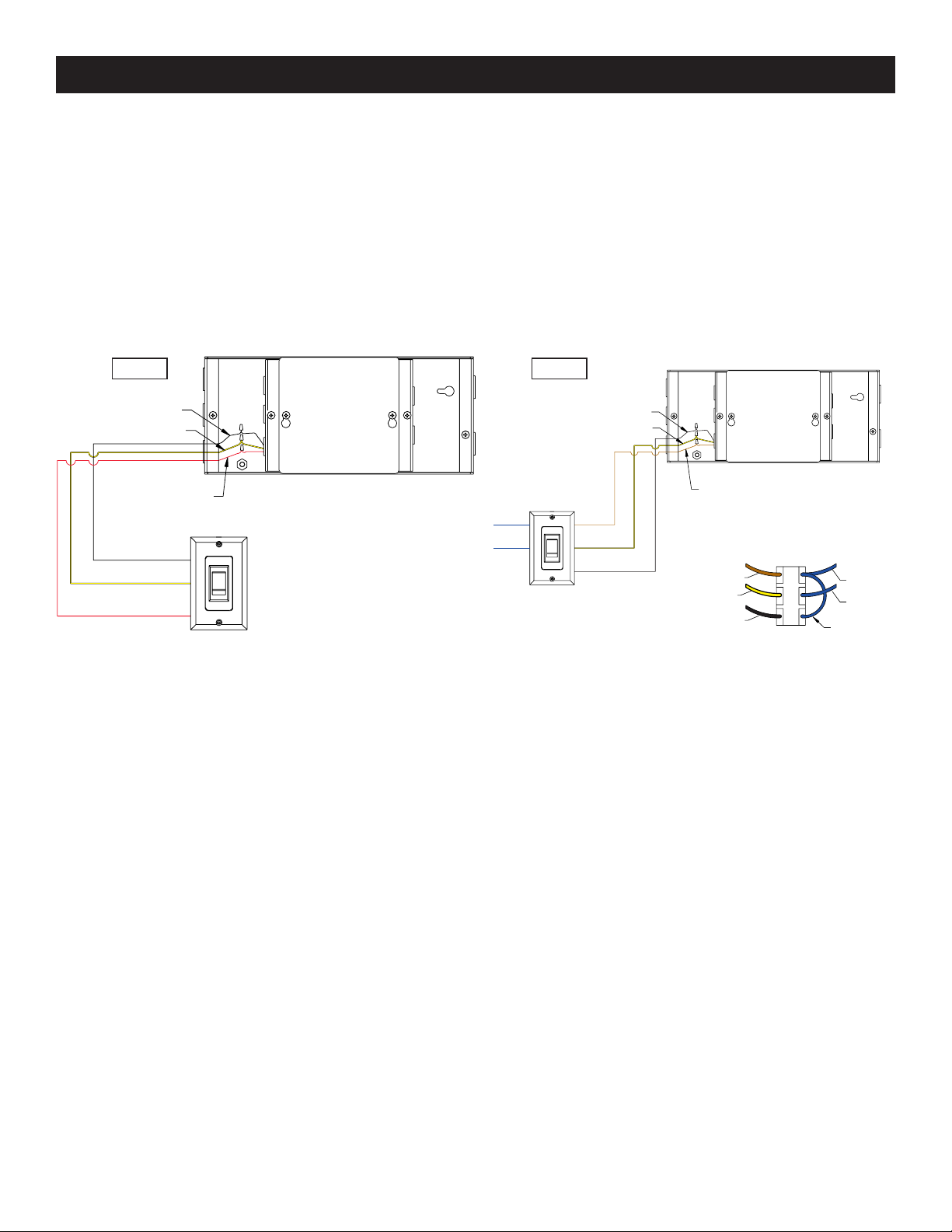
Wall Switch
1. Using 3-conductor, 14-18 gauge wire, extend the wall switch wires from the back of the wall switch to the length
required to reach the VPI.
2. Connect the extended wires from the wall switch to the VPI wires that are labeled “wall switch”. Refer to Figure 4.
3. The wall switch must be placed in the “up” position for the screen to be triggered by the projector.
4. If a wall switch is not being used, please do the following. For 120V units, the black/yellow lead and the red lead for
the wall switch must be connected to each other and the black lead must be capped. For 240V units, the
black/yellow lead and the black lead for the wall switch must be connected to each other and the brown lead must
be capped.
AC POWER CONNECTIONS
BLACK
BLACK/YELLOW
FIGURE 4
RECOMMENDED WIRE SIZE: 14-18 AWG
BLACK
BLACK/YELLOW
RECOMMENDED WIRE SIZE: 14-18 AWG
120V 240V
BLUE TO
MOTOR
BLUE TO
POWER
SOURCE
BACK OF SWITCH
BROWN
BLACK/YELLOW
BLACK
BLUE TO
MOTOR
BLUE TO
POWER
SOURCE
BLUE
JUMPER
RED
BLACK
BLACK/YELLOW
RED
DOWN
UP
BROWN
BROWN
BLACK/YELLOW
BLACK
DOWN
UP
 Loading...