

Page 1
The Da-Lite Difference.
Installation and Operating Instructions For
SINGLE MOTOR LOW VOLTAGE
CONTROL SYSTEM
DA-LITE SCREEN COMPANY, INC.
3100 North Detroit Street
Post Office Box 137
Warsaw, Indiana 46581-0137
Phone: 574-267-8101
800-622-3737
Fax: 574-267-7804
www.da-lite.com
e-mail: [email protected]
Page 2
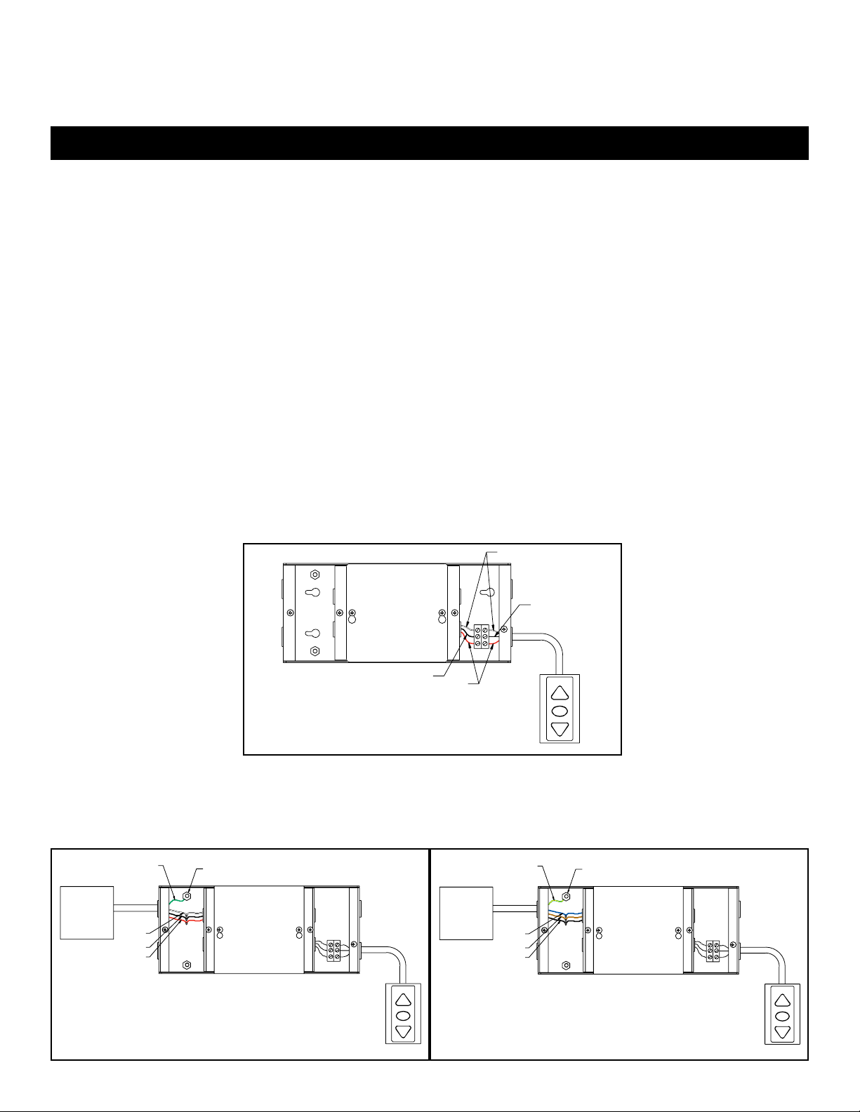
The low voltage control (LVC) housing is divided into 3 compartments. the compartment labeled “Low Voltage
Connections” is where you will connect the wall switch or a central control panel. The compartment labeled “AC Power
Connections” is where the main power and motor wire connections are made. The center compartment only requires
access when connecting an infrared or radio frequency remote receiver.
INSTALLATION
WARNING: To prevent electrical shock or damage to the LVC, do not apply power to the LVC until all connections are
complete. Make sure power is turned off on all wires before making connections.
LOW VOLTAGE CONNECTIONS:
Wall Switch
WARNING: This unit must be used with the enclosed switch. DO NOT USE the rocker switch included with screen.
1. Install wall switch where desired.
2. Use 3-conductor 20-24 gauge wire to extend the switch wire to the required length.
3. Connect the wire from the switch to the wire labeled “wall switch”. Refer to diagram 1.
CAUTION: Never apply voltage to the wall switch lead or the LVC will be damaged.
!
s
Control Panel
A control panel may be connected to the LVC by using the wall switch wire lead. The control panel must provide a
momentary, dry contact closure of at least 1/2 second.
1. Use 3-conductor 20-24 gauge wire to connect the control panel to the wall switch lead.
2. A momentary closure across the white and red wires will be an “up” command.
3. A momentary closure across the white and black wires will be a “down” command.
4. A momentary closure across the white, red and black wires will be a “stop” command.
CAUTION: Never apply voltage to the wall switch lead or the LVC will be damaged.
!
s
WHITE
Diagram 1
BLACK
BLACK
Recommended Wire Size: 20-24 AWG
RED
LOW-VOLTAGE
WALL SWITCH
UP
STOP
DOWN
AC POWER CONNECTIONS:
Screen Motor
1. Connect the motor wires in the screen junction box to the LVC wires labeled “motor wires”. Refer to diagram 2.
2. Use 14-18 gauge wire to extend the motor wire to the required length.
GREEN
GROUND
SCREEN
WHITEWHITE
BLACK-BLACK
RED-RED
Recommended Wire Size: Recommended Wire Size:
14-18 AWG 14-18 AWG
Diagram 2
120VAC 60Hz 240 VAC 50Hz
GROUND LUG
UP
STOP
DOWN
GREEN/YELLOW
GROUND
SCREEN
BROWN-BROWN
BLACK-BLACK
BLUEBLUE
GROUND LUG
UP
STOP
DOWN
1
Page 3
INSTALLATION
AC Power Source
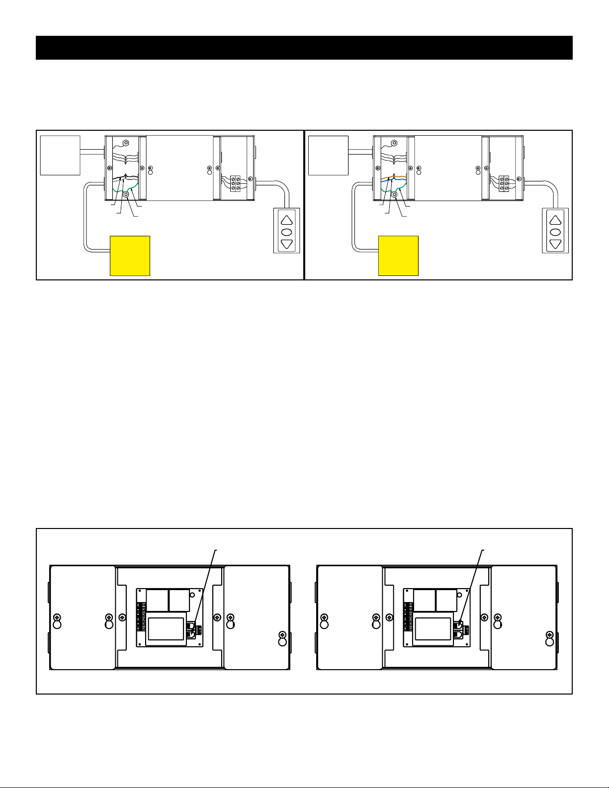
1. Connect power wires to the LVC wires labeled “AC power input”. Refer to diagram 3.
2. Connect the building ground wire to the ground lug on the metal housing.
BLACK HOT
WHITE
COMMON
Recommended Wire Size: Recommended Wire Size:
14-18 AWG 14-18 AWG
POWER
SOURCE
120VAC
60HZ
GREEN GROUND
GROUND LUG
UP
STOP
DOWN
BROWN HOT
BLUE
COMMON
POWER
SOURCE
240VAC
50HZ
GREEN GROUND
GROUND LUG
UP
STOP
DOWN
Diagram 3
OPTIONAL WIRELESS REMOTE CONNECTIONS:
Radio Frequency Remote
1. Remove the cover plate labeled “Low voltage connections” and the center cover plate.
2. Route the receiver wire through the round plastic bushing and plug it into the onboard socket marked “EYE”. Refer
to diagram 4.
Infrared Remote
1. Remove the cover plate labeled “Low voltage connections” and the center cover plate.
2. Route the receiver wire through the round plastic bushing and plug it into the onboard socket marked “EYE”. Refer
to diagram 4.
Diagram 4
120VAC 60HZ
EYE AUX
OPTIONAL RF REMOTE,
IR REMOTE OR VIDEO
PROJECTOR INTERFACE
CONNECTOR
240VAC 50HZ
AUX EYE
OPTIONAL RF REMOTE,
IR REMOTE OR VIDEO
PROJECTOR INTERFACE
CONNECTOR
2
Page 4
TROUBLESHOOTING
Visit www.da -lite.com/products/tutorials.php to find installation and troubleshooting tutorials. You will also
find a link to Live Chat for interactive support and you can contact us by email at [email protected] or by phone
at (800) 622-3737 or (574) 267-8101 with any troubleshooting questions.
SYMPTOM
1. Screen will not operate.
(b)
(d)
2. Radio frequency remote does not
work.
3. Infrared remote does not work.
b
c
4. Screen runs in the wrong
direction.
CAUSE
(a) No power to LVC unit.
(b) Incorrect wiring.
(c) Low voltage circuit damaged due
to voltage input.
(d) LVC controller lock-up
(a) Weak battery in transmitter.
(a) Weak battery in transmitter.
(b) Receiver incorrectly positioned.
(c) Fluorescent light interference.
(a) Red and black wires are reversed
on motor or wall switch
terminals.
SOLUTION
(a) Turn on power to LVC input.
Measure voltage across black
and white input leads.
(b) Recheck all wiring for proper
installation. Check all wire nut
connections.
(c) The wall switch terminal is for
dry contact (no voltage) input
only. Applying voltage to this
terminal will damage the LVC.
(d) Locate breaker for screen and
turn off power. Wait one minute
and re-activate circuit.
(a) Replace battery.
(a) Replace battery.
(b) Receiver must be unobstructed
and located in direct line with the
transmitter.
(c) Remote receiver should not be
placed near fluorescent lights.
(a) Turn off power to LVC. Reverse
the red and black wires on either
the motor terminals or the wall
switch terminals. Changing either
one will change the direction of
motor travel. Do not change
both.
NOTE: The LVC will shut off power to the screen motor 5 minutes after the motor stops turning. Push the up or down button to
reactivate the LVC relays.
3Printed in U.S.A. 98885 Rev. 4/11
 Loading...