

Page 1

The
POWER
PRESENTATION PRODUCTS
In
Instruction Book for
DESIGNER CONTOUR®ELECTROL
®
DA-LITE SCREEN COMPANY, INC.
3100 North Detroit Street
Post Office Box 137
Warsaw, Indiana 46581-0137
Phone: 574-267-8101
800-622-3737
Fax: 574-267-7804
Toll Free Fax: 877-325-4832
www.da-lite.com
e-mail: info@da-lite.com
Page 2

IMPORTANT SAFETY INSTRUCTIONS
When using your video equipment, basic safety precautions
should always be followed, including the following:
1. Read and understand all instructions before using.
2. Position the cord so that it will not be tripped over, pulled,
or contact hot surfaces.
3. If an extension cord is necessary, a cord with a current
rating at least equal to that of the appliance should be used.
Cords rated for less amperage than the appliance may
overheat.
4. To reduce the risk of electric shock, do not disassemble this
appliance. Contact an authorized service dealer when repair
work is required. Incorrect reassembly can cause electric
shock when the appliance is used subsequently.
5. The use of an accessory attachment not recommended by
the manufacturer may cause a risk of fire, electric shock, or
injury to persons.
SAVE THESE INSTRUCTIONS
1
Page 3
INSTALLATION
Carefully unpack screen and remove outer wrapping from
case.
Remove the black tape from the slat bar after the case has
been installed.
here are three ways to install the Designer Contour Electrol:
T
Wall Mount, Ceiling Mount, or Ceiling Hook. Procedures for
each method are as follows:
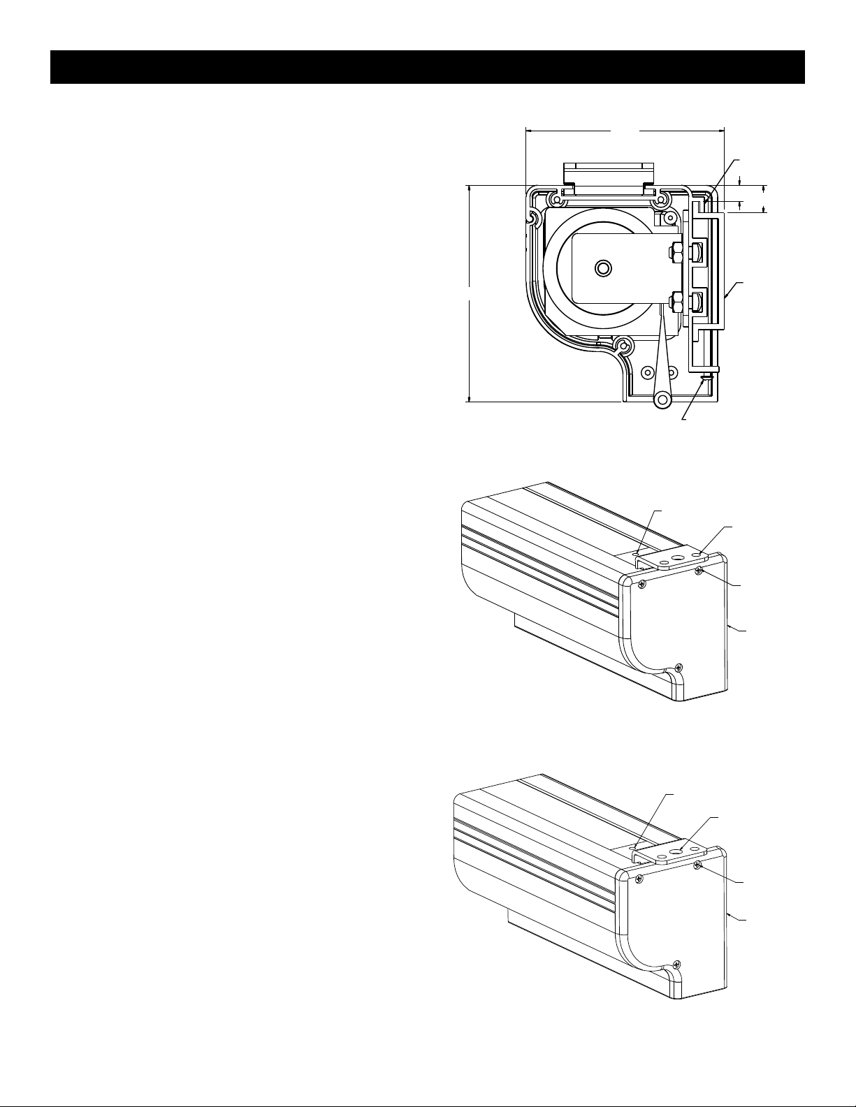
Wall Mount
1. Secure the wall mount bracket to the wall at the
desired height. Bracket should be fastened to wall
studs or some reinforcement within the wall. Concrete
or brick walls require special fasteners and anchors.
2. Make sure the bracket is level. See figure 1 for
reference dimensions.
3. Keep in mind you will need at least 5/8" between the
ceiling and the top of the wall mount bracket to be able
to position the case on the bracket.
4. Mount the screen case on the wall bracket as shown
in figure 1. Be sure the case is fully seated on the
bracket. Tighten the stop screws against the wall
bracket.
Ceiling Mount
1. Do not remove the wall mount bracket, even if you are
not using it for mounting. This provides structural
stability to the case.
2. Be sure the ceiling has adequate reinforcement to
attach the screen brackets.
3. The top of the screen case has a channel that the
ceiling mount brackets slide into. Remove the end cap
on the right end of the case and insert the brackets
into the case channel. Lock the brackets in place by
tightening two set screws. Refer to figure 2. Mount
cannot be more than 12" from end of case.
4. Hold the screen case up to the ceiling and mark the
hole locations. Drill holes into the ceiling and attach
screen with the appropriate fasteners for your ceiling.
Ceiling Hook
1. Do not remove the wall mount bracket, even if you are
not using it for mounting. This provides structural
stability to the case.
2. Be sure the ceiling has adequate reinforcement to
attach a hook anchor.
3. The top of the screen case has a channel that the
ceiling hook brackets slide into. Remove the end cap
on the right end of the case and insert the brackets
into the case channel. Lock the brackets in place by
tightening two set screws. Refer to figure 3.
4. The brackets can be attached anywhere within 12" of
the end of the case.
5. Attach an S-hook or similar fastener to the large center
hole on the bracket.
4-5/8"
4-1/4"
FIGURE 1
FIGURE 2
FIGURE 3
CASE HOOK
5/16"
MOUNT
BRACKET
STOP SCREW
SET SCREWS (2)
CEILING
MOUNT
HOLES
SET SCREWS (2)
HOOK MOUNT
HOLE
9/16"
WALL
ENDCAP
SCREWS
(3)
ENDCAP
ENDCAP
SCREWS
(3)
ENDCAP
2
Page 4

ELECTRICAL INSTALLATION
Internal wiring has been completed at the factory. Installer must route power to the wall switch and to the junction box
ocated on the left end of the screen case.
l
Standard installation is for a single 120VAC or 240VAC wall switch to control the screen. Optional Control units may have
been ordered. Wiring diagrams for the built-in VPI and low voltage control are included in these instructions. Refer to
dditional instructions for the external VPI, external low voltage control, SCB-100 and SCB-200. Refer to the appropriate
a
wiring diagram for your screen.
120V WIRING DIAGRAM
FOR STANDARD
WALL SWITCH
UNCTION BOX
J
OCATED IN LEFT ENDCAP
L
SPDT SWITCH WITH
CENTER OFF
G
ROUND–MUST BE CONNECTED
G
O BUILDING GROUND
BLACK (DOWN)
RED (UP)
T
AC (COMMON)
WHITE
HITE
W
LACK
B
RED
GREEN
ROUND TO CASE
M
OTOR
UP
OFF
DOWN
THIS SWITCH CAN NOT
BE USED WITH LVC.
BLACK
AC HOT 120VAC 60HZ 1 AMP
RED
NOTE: A SINGLE SWITCH CANNOT BE USED TO OPERATE MORE THAN
ONE SCREEN. CONTACT THE FACTORY FOR FURTHER
INFORMATION.
BLACK/YELLOW
240 VOLT WIRING DIAGRAM
FOR STANDARD WALL SWITCH:
Da-Lite offers two styles of 240 volt
wall switches for standard operation.
Please see wiring diagram included in
wall switch box included with screen.
3
Page 5

ELECTRICAL INSTALLATION
120V WIRING DIAGRAM
WITH OPTIONAL BUILT-IN
LOW VOLTAGE CONTROL
OTOR
M
G
ED
R
BLACK
WHITE (COMMON)
ROUND TO CASE
LACK
B
HITE
W
ED
R
EYE AUX
UP
STOP
DOWN
120VAC 60HZ
GROUND–MUST BE
CONNECTED TO
BUILDING GROUND
WHITE (COMMON)
BLACK (HOT)
GREEN
240V WIRING DIAGRAM
WITH OPTIONAL BUILT-IN
LOW VOLTAGE CONTROL
MOTOR
BLACK (UP)
BROWN (DOWN)
BLUE (COMMON)
GROUND TO CASE
BLACK
LOW-VOLTAGE
OPTIONAL RF
WALL SWITCH
OR IR REMOTE
CONNECTOR
OPTIONAL RF OR IR
REMOTE CONNECTOR
BLACK
WHITE
RED
AUX EYE
UP
STOP
DOWN
240VAC 50HZ
GROUND–MUST
BE CONNECTED
TO BUILDING
GROUND
BLUE (COMMON)
BROWN (HOT)
GREEN
BLACK
LOW-VOLTAGE
WALL SWITCH
4
Page 6

SCREEN ADJUSTMENT
Screen travel is stopped automatically in the down and up
ositions by the limit switches that are preset at the factory. If
p
it’s necessary to adjust for more or less drop follow the steps
below. The case cover must be removed to access the motor
limit switches.
Remove the case cover screw from both ends of the screen.
See figure 4. Be sure to hold the cover while removing the
screws.
Rotate the cover up and away from the case until it can be
removed.
SETTING THE DOWN LIMIT POSITION
TO REDUCE SCREEN DROP:
Turn the red limit switch screw clockwise to decrease the
amount of screen drop. Run the screen down to test the
stop position. If the screen drops too far, raise the screen
about one foot and adjust the limit switch again. Repeat
until the desired position is set.
TO INCREASE SCREEN DROP:
Turn the red limit switch screw counterclockwise to
increase the amount of screen drop. Run the screen
down to test the stop position. If the screen does not
drop enough, raise the screen about one foot and adjust
the limit switch again. Repeat until the desired position is set.
CAUTION: Do not adjust for more drop than what was ordered. At least 1-1/2 wraps of fabric must remain on the roller. This
!
screen comes standard with 0" or 2" black at top. See the specification data sheet for details.
▲
FIGURE 4
HOOK
ROTATE UP
FIGURE 5
CASE COVER
SCREW
5
Page 7

TROUBLESHOOTING
SYMPTOM
1. Screen will not operate.
Motor does not hum.
CAUSE
(a) Incorrect line voltage.
b) Blown fuse.
(
(c) Tripped circuit breaker.
(d) No power to operating switch
or junction.
Power at junction box
(e) Thermal overload tripped.
(f) Broken wire in the “down” or “up”
position.
SOLUTION
(a) Verify 115-125V (or 220-240V). If
insufficient voltage, rewire
incoming electric line.
b) Replace fuse.
(
(c) Reset circuit breaker.
(d) Check above. Tighten all loose
wire connections. Correct any
improper connections.
“Down” Position
Check for power across black
and white leads.
“Up” Position
Check for power across red
and white leads.
(e) Let motor cool down for 15
minutes. Try again.
(f) Check for continuity. Cut off old
splice and reconnect.
2. Incorrect stopping position in
downward direction.
3. Incorrect stopping position in
upward direction.
4. Noise.
NOTE: Screen will operate with a
low pitched hum.
5. Coasting.
(g) Defective motor, limit switch or
capacitor.
(h) Capacitor burned out.
(a) Lost roller wrap.
(b) “Down” limit switch out of
adjustment
(a) Lost roller wrap.
(b) “Up” limit switch out of
adjustment
(a) Gear Noise.
(a) Defective brake.
RESTORING LOST ROLLER WRAP
1. Tape a strap to the bottom of the
screen surface.
2. Push strap over back of roller.
3. Feed fabric as you pull strap to
draw fabric over top of roller.
4. Remove tape and strap.
(g) Replace motor assembly.
NOTE: Motor is a sealed assembly.
(h) Replace motor assembly.
(a) See instructions below.
(b) See installation instructions.
(a) See instructions below.
(b) Adjust “up” limit switch. Call for
information
(a) Replace motor assembly.
(a) Replace motor assembly.
6
Page 8

Printed in U.S.A. 89697 Rev. 7/09
 Loading...