

Page 1

INSTALLATION AND OPERATING INSTRUCTIONS FOR
Dual Motor Low Voltage Control (DMC)
Page 2
Important Safety Instructions
When using your video equipment, basic safety precautions should always be followed, including the following:
1. Read and understand all instructions before using.
2. Position the cord so that it will not be tripped over, pulled, or
contact hot surfaces.
3. If an extension cord is necessary, a cord with a current rating at
least equal to that of the appliance should be used. Cords rated
for less amperage than the appliance may overheat.
Save These Instructions
Installation
WARNING: To prevent electrical shock or damage to the Dual
Motor Low Voltage Control (DMC), do not apply power to the
DMC until all connections are complete. Make sure power is
turned of on all wires before making connections.
AVERTISSEMENT: pour éviter tout choc électrique ou
d'endommager le tableau de contrôle basse tension,
n'alimentez ce dernier qu'une fois tous les branchements
efectués. Vériiez qu'aucun câble n'est alimenté avant
d'efectuer les branchements
Opening the Unit
4. To reduce the risk of electric shock, do not disassemble this
appliance. Contact an authorized service dealer when repair
work is required. Incorrect reassembly can cause electric shock
when the appliance is used subsequently.
5. The use of an accessory attachment not recommended by the
manufacturer may cause a risk of ire, electric shock, or injury to
persons.
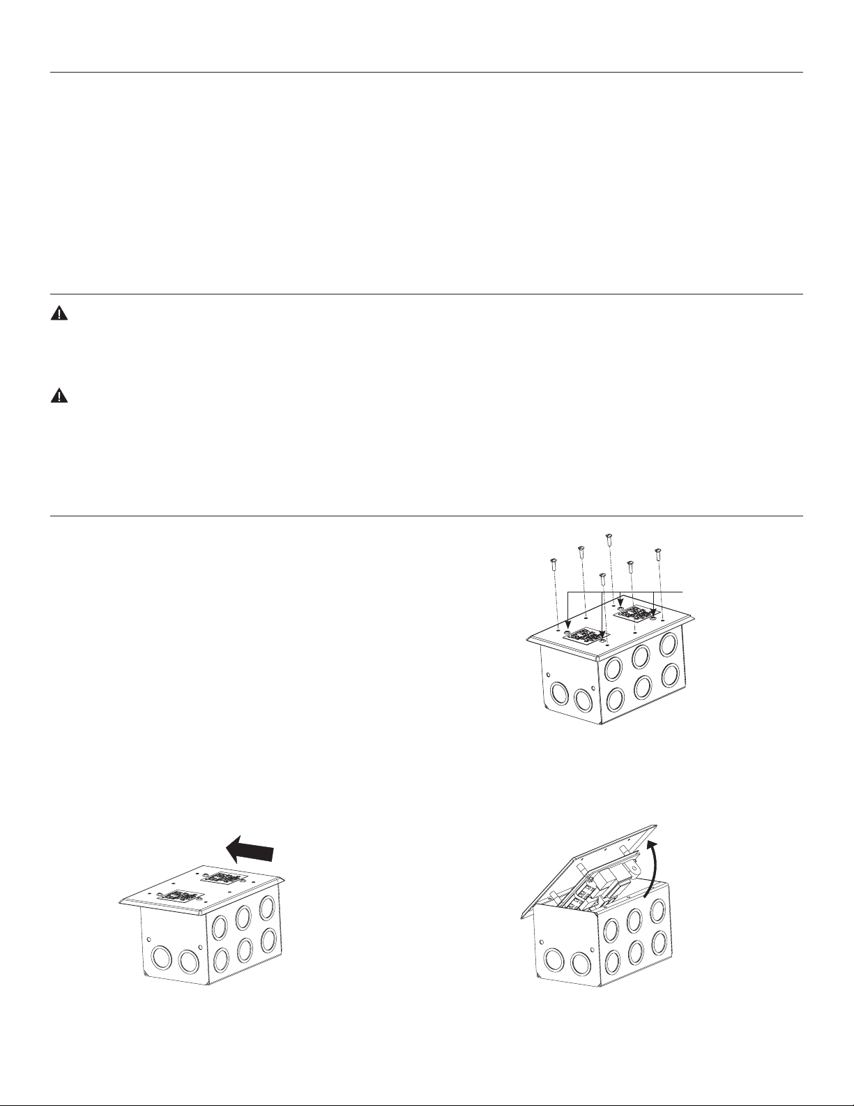
To open the unit, please follow these instructions and Figures 2,
3, and 4.
1. Remove the six screws that hold the cover plate to the box
(DO NOT REMOVE the 4 screws in the middle of the cover
plate; these hold the circuit board to the cover plate.)
See Figure 2.
2. Upon removing the screws, push the cover plate to the side
of the box. See Figure 3.
3. Rotate up and remove. See Figure 4..
Push Cover To Side
Do Not Remove
These 4 Screws
Figure 2
Rotate Cover
Upward After
Sliding To
Side
Figure 3 Figure 4
2
Page 3
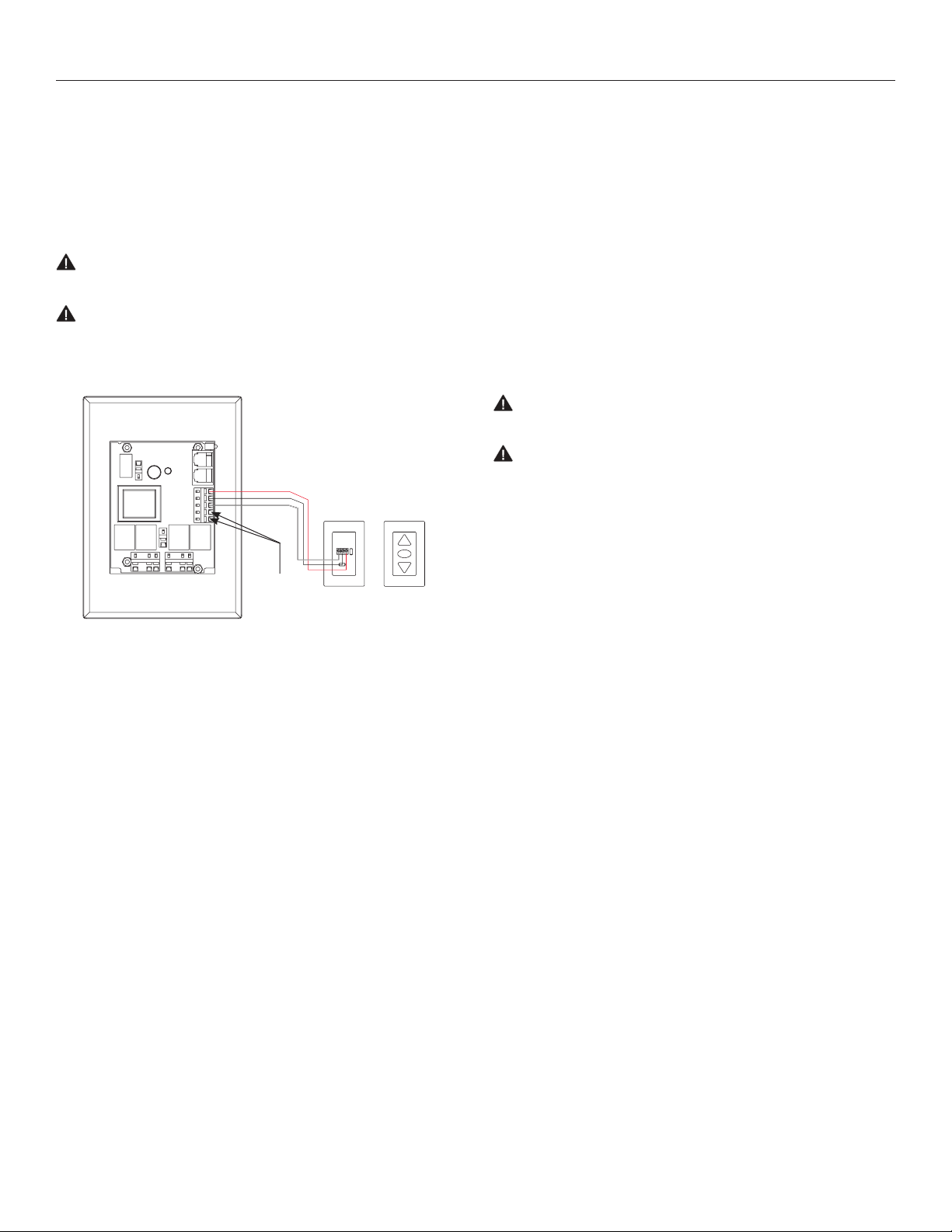
Low Voltage Connections:
Wall Switch
1. Install wall switch where desired.
2. Use 3-conductor 2024 gauge wire to extend the switch wire
to the DMC location.
3. Connect the wire from the switch to the switch terminal as
shown in Figure 5.
CAUTION: Never apply more than 24 volts to the wall switch
terminal or the DMC will be damaged.
ATTENTION: n'alimentez jamais le commutateur mural avec
plus de 24 volts ou la commande double du moteur sera
endommagée.
Red - Up
Black - Down
White – Common
Not
Used
Back Of
Wall
Switch
Front Of
Wall
Switch
Up
Stop
Down
Third Party Control System
A third party control system may be connected to the DMC by using
the wall switch terminal. The third party control system must provide
a momentary, dry contact closure of at least 1/2 second.
1. Use 3-conductor 2024 gauge wire to connect the third party
control system to the wall switch terminal.
2. A momentary closure across the white and red wires
will be an “up” command.
3. A momentary closure across the white and black wires will
be a “down” command.
4. A momentary closure across the white, red and black wires will
be a “stop” command.
CAUTION: Never apply more than 24 volts to the wall switch
terminal or the DMC will be damaged.
ATTENTION: n'alimentez jamais le commutateur mural avec
plus de 24 volts ou la commande double du moteur sera
endommagée.
Figure 5
3
Page 4

AC Power Connections
Dual Masking Electrol®
1. Connect the motor wires in the screen junction box to the DMC terminals as shown in Figures 6 or 7.
2. Use 1418 gauge wire to extend the motor wire to the required length.
120VAC 60Hz 240VAC 50Hz
Up
Stop
Down
White – Common
Black - Up Brown - Up
Screen
Red - Down Black - Down
Motor
Red - Down Black - Down
Black - Up Brown - Up
White – Common
Mask
Motor
Screen
Motor
Blue – Common
Blue – Common
Figure 6 Figure 7
Two Electrol® Screen Application
(Not for use with Ascender®, Horizon, or Motorized Scenic Roller. Cannot be used with other Electrol® models with a
built in Low Voltage Control.)
In this application, the second screen cannot be controlled independently.
1. Use 1418 gauge wire to extend the motor wires to the DMC location.
2. Connect the motor wires in the screen junction boxes to the DMC as shown in Figures 8 or 9.
120VAC 60Hz 240VAC 50Hz
Mask
Motor
Up
Stop
Down
Up
Stop
Down
Screen
Motor
Up
Stop
Down
White – Common Blue – Common
Red - Up
Black - Down Brown - Down
Black - Down
Red - Up
White – Common Blue – Common
Screen
Motor
Screen
Motor
Black - Up
Brown - Down
Black - Up
Screen
Motor
Figure 8 Figure 9
4
Page 5

AC Power Connections
Electrol® Screen and Da-Lift Projector Lift
(Not for use with Ascender®, Horizon, or Motorized Scenic Roller. Cannot be used with other Electrol®
models with a built in Low Voltage Control.)
1. Use 1418 gauge wire to extend the motor wires to the DMC location.
2. Connect the motor wires in the screen and Da-Lift junction boxes to the DMC as shown in Figures 10 or 11.
120VAC 60Hz 240VAC 50Hz
Up
Stop
Down
Screen
Motor
White – Common Blue – Common
Red - Up Black - Up
Black - Down Brown - Down
Red - Down Black - Down
Black - Up Brown - Up
White – Common Blue – Common
Projector
Lift Motor
Figure 10 Figure 11
AC Power Source
1. Connect power wires to the DMC terminal as shown in Figures 12 or 13.
2. Grounding continuity: If metallic conduit is not used throughout the screen
and control installation, grounding conductors are required to provide
ground continuity between the screen and the DMC
Power Source
120VAC 60Hz
White - Common
Black - Hot
Screen
Motor
Power Source
240VAC 50Hz
Blue - Common
Brown - Hot
Projector
Lift Motor
Up
Stop
Down
Up
Stop
Down
Figure 12 Figure 13
Up
Stop
Down
5
Page 6

Operating the Dual Motor Controller Optional Wireless Remote Connections:
Motor A Only
1. Press the DOWN button once and the screen descends.
2. Press the UP button once and the screen ascends.
Motor A and B Combination
1. Press the DOWN button once and the screen descends.
2. Press the DOWN button again and the mask, second screen,
or projector lift descends.
3. Press the UP button once and the mask, second screen,
or projector lift ascends.
4. Press the UP button again and the screen ascends.
Radio Frequency Remote
1. Attach the receiver adjacent to the DMC. Route the receiver wire
into the DMC and plug it into the onboard socket. Refer to Figure
14.
Infrared Remote
1. Attach the receiver in a location visible from where the screen
will be operated and away from luorescent lights. Route the
receiver wire into the DMC and plug it into the onboard socket.
Refer to Figure 14.
Plug Optional IR
Or RF Receiver
Unit In Here
Figure 14
Page 7

Page 8

A Milestone AV Technologies Brand
3100 North Detroit Street
Warsaw, Indiana 46582
P: 574.267.8101 or 800.622.3737
F: 574.267.7804 or 877.325.4832
E: info@da-lite.com
www.da-lite.com
DL–0371 (Rev. 1) 09.14
© 2014 Milestone AV Technologies LLC. Printed in U.S.A.
95491
 Loading...