

Page 1
INSTRUCTION BOOK FOR
Da-Lift Projector Lift
10M, 15M, 15, 19, 19L
Page 2

Important Safety Instructions Pre-Installation
When using your video equipment, basic safety precautions
should always be followed, including the following:
1. Read and understand all instructions before using.
2. Position the cord so that it will not be tripped over, pulled, or
contact hot surfaces.
3. If an extension cord is necessary, a cord with a current rating at
least equal to that of the appliance should be used. Cords rated
for less amperage than the appliance may overheat.
4. To reduce the risk of electric shock, do not disassemble this
appliance. Contact an authorized service dealer when repair
work is required. Incorrect reassembly can cause electric shock
when the appliance is used subsequently.
5. The use of an accessory attachment not recommended
by the manufacturer may cause a risk of ire, electric shock,
or injury to persons.
Save These Instructions
This unit must be installed in accordance with the requirements
of the Local Building Codes, the Canadian Electrical Code (CEC),
CAN/CSA C22.1 and the National Electric Code (NEC) NFPA 70.
1. Carefully unpack Da-Lift projector lift.
2. Make sure to recheck measurements of projector lift location
before installation.
2
Page 3
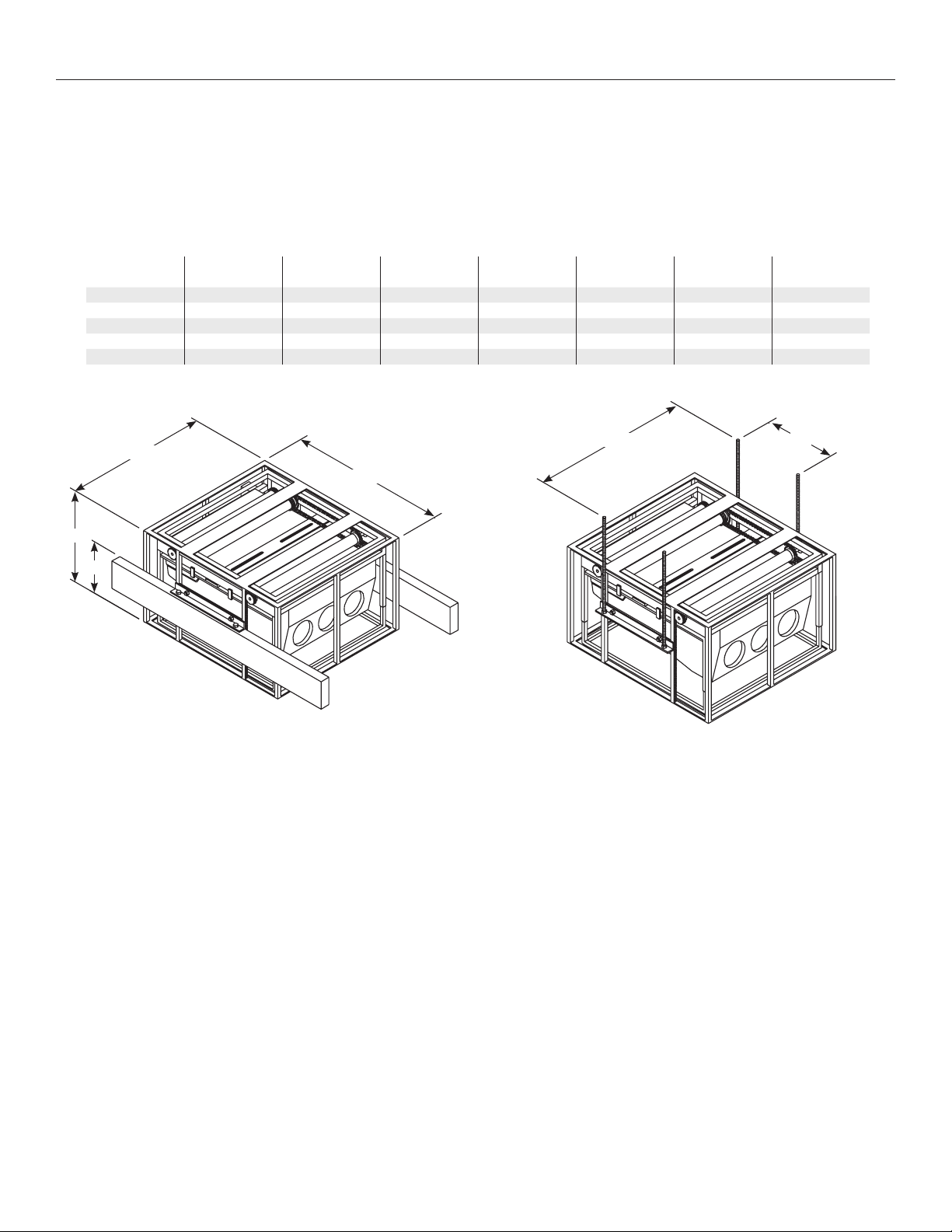
Suggested Methods Of Installation
1. Mounting Da-Lift Projector Lift between joists.
Install the joists at the proper height and width to it the Da-Lift
you are installing. See Figure 1.
NOTE: The Da-Lift must be installed on top of the joists.
Be sure to leave access from above for installation.
Model
Da-Lift 10M 40 lbs. 22⅝” 15” 22” 4½” 24⅛” 14”
Da-Lift 15M 40 lbs. 22⅝” 20” 22” 9½” 24⅛” 14”
Da-Lift 15 300 lbs. 30¾” 20” 34” 9½” 32¼” 16¼”
Da-Lift 19 300 lbs. 32¾” 24” 38” 13½” 34¼” 16¼”
Da-Lift 19L 300 lbs. 42¾” 24” 48” 13½” 44¼” 16¼”
Lifting
Capacity
Width
A
Height
B
A
C
B
When the joists are properly installed, and secured in place, slide
the Da-Lift in position. Bolt the two brackets (11/2” x 19”) to the
frame. Lower the unit onto the joists and secure in place.
Additional bracing may be required, based on construction.
NOTE: Da-Lift projector lift must be installed level!
Depth
C
Height
D
E
DIm.
E
Dim.
F
F
D
Figure 1 Figure 2
2. Mounting Da-Lift Projector Lift using 1/2” diameter threaded rods.
Secure four 1/2” diameter threaded rods to the ceiling at the
dimensions shown. See Figure 2, “E” and “F”. Install the mounting
bracket (11/2” x 19”) to each side of Da-Lift with 1/2” diameter bolts,
lat washers and nuts. Attach one nut on each rod and run the
nut up to the desired height.
Slide Da-Lift projector lift up with all (4) four threaded rods into
the mounting brackets. Install 1/2” nuts under the mounting
brackets. Adjust the frame to the proper height and level with
bottom nuts on the rod. Lock the mounting brackets in place
with the nuts on the top of each rod. Frame must be level and
solid. Additional bracing may be required, based on construction.
3
Page 4

Electrical Wiring
1. Install electrical hook up that applies to your unit. Make sure to
review your Electrical Installation Checklist and wiring diagram
(see Figure 3) for 120-volt switch, 220/240-volt switch, or DRC
low voltage control.
NOTE: Da-Lift projector lift has been internally wired at
Da-Lite. External wiring is completed by installer conforming
to local and national codes. Be sure the wires are long
enough for the Da-Lift to go up and down.
120V Wiring Diagram
Up Limit
Switch N.C.
Opens When
Operated
Black (Hot)
White (Common)
120V.
Plug-In For T.V.
White (Common)
120V.
Black (Hot)
2. Test installation by carefully running Da-Lift “up” and “down”
several times. Be prepared to stop the Da-Lift. Duty cycle is three
(3) minutes ON and three (3) minutes OFF.
3. Make sure Da-Lift stops in the up direction lush with the ceiling.
Black
Junction
Box
Black
Green
Black
RedRedRed (Down)
WhiteWhite
BlackBlack (Up)
Operating Switch,
Switch Box, And
Plate Furnished With
Da-Lift. (SPDT With
Center Of)
Figure 3
This Switch Cannot
Be Used With L.V.C.
Side View Of
Switch & Box
Red (Down)
Up
Of
Down
Black (Up)
240 Volt Wiring Diagram
Da-lite ofers two styles of 240-volt wall switches for standard operation.
Please see wiring diagram included in wall switch box included with screen.
White (Common)
AC Common
AC Hot
120V. AC 60Hz.
2.2 AMP. Max
Black & Yellow
4
Page 5

Da-Lift Projector Lift Adjustment
Models 15, 19, 19L
Da-Lift projector lift travel is stopped automatically in the full up
and full down positions by limit switches, which have been
properly adjusted at the factory. The up limit switch should not
be ield adjusted. If it is necessary to readjust the down limit
switch, proceed in the following manner. See Figure 4. Raise
projector lift before adjustment for less drop. Take a small
screwdriver or 5/32” hex wrench and insert in yellow switch and
turn towards the (-) or clockwise direction. Raise and then lower
Drive Motor
Limit Switch Adjustment
Figure 4
the Da-Lift and check for proper stopping height. If additional
change is necessary, repeat steps until the proper height is set.
Check for satisfactory condition by operating unit a few times.
The bottom frame of the Da-Lift is removable and adjustable to
ceiling level. Finish the bottom frame to match the ceiling.
Down
Yellow
Up
White
Models 10M, 15M
Use a small screwdriver or 5/32” hex wrench and insert in
number 2 switch. Turn clockwise for less drop. Check for proper
stopping height. Repeat steps until the proper height is set.
See Figure 5.
Figure 5
2
Down
Limit Switch Adjustment
1
Up
The bottom frame of the Da-Lift is removable and adjustable
to ceiling level. Finish the bottom frame to match the ceiling.
Drive Motor
5
Page 6

Optional
Install 11/2 pipe coupling plate for a projector mount. See Figure 6. Loosen set screws to move Mount Channel.
Tighten set screws to hold position.
⅜" Screws,
Washers,
Mount
And Nuts
Channel
Figure 6
Coupling Plate
Optional
Finish the Ceiling Tile Plate by attaching a ceiling tile to it, painting it or other inishing ideas. See Figure 7.
Use the adjustable Bottom Frame to position the Ceiling Tile Plate level with the ceiling.
Set Screws
Figure 7
Screws
Holding
Frame
Frame
Can
Adjust
Vertically
Screw
Holding
Ceiling
Tile Plate
Ceiling Tile
Plate Can
Adjust
Page 7

Page 8

A Milestone AV Technologies Brand
3100 North Detroit Street
Warsaw, Indiana 46582
P: 574.267.8101 or 800.622.3737
F: 574.267.7804 or 877.325.4832
E: info@da-lite.com
www.da-lite.com
DL–0368 6.14
© 2014 Milestone AV Technologies LLC. Printed in U.S.A.
78100
 Loading...