

Page 1
Quick Guide: Digit Display Installation with FLR-500 Control Kit p. 1
Note: This guide begins after the displays have been physically mounted.
Signal Installation
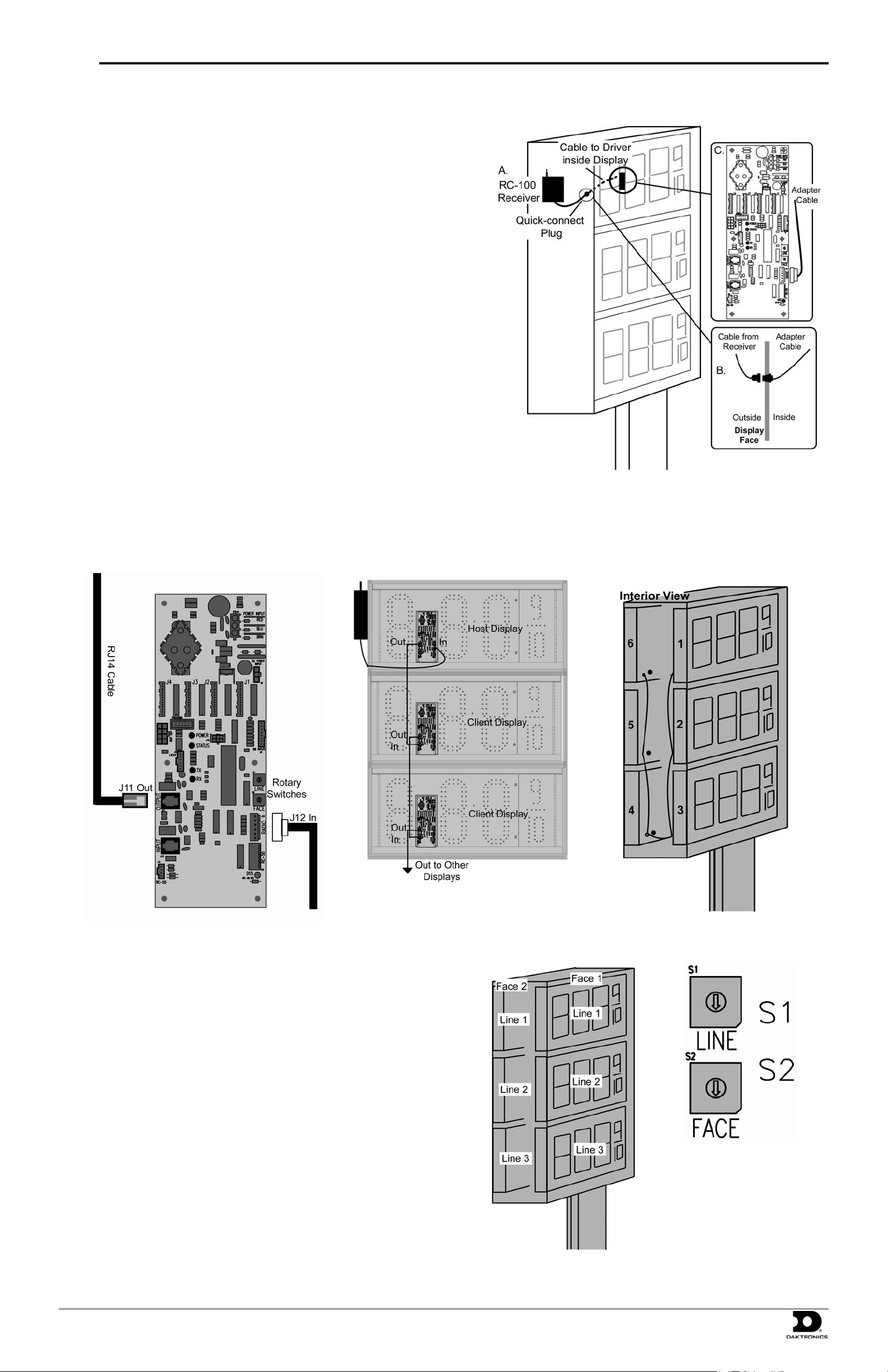
1. Choose a location for the receiver on the side of a display that faces the
building. The location should be high off the ground with an
unobstructed line-of-sight to the store.
2. Mount the radio receiver to the chosen location using screws (Figure 1,
A). Take care not to damage the display to help prevent water from
entering the display and damaging the internal components.
3. Mount the adapter cable quick-connect jack to the display cabinet so that
the receiver quick-connect can be attached from the outside (Figure 1, B).
A 5/8” hole will be required.
4. Grease each signal jack with electrical contact grease before making the
following signal connections.
5. Connect the quick-connect from the receiver to the adapter cable.
6. Plug the other end of the adapter cable into the driver board 6-pin jack
(J12), as shown in Figure 1, C.
7. Remove the signal knockouts on the backs of each display. Insert
conduit fittings over the rough edges.
8. Starting with the driver board plugged into the receiver (the host
display), plug the RJ14 cable into the output jack (J11).
9. Plug the other end of this cable into the Input jack (J13) on the next display driver. Continue with this pattern, going from the output of one
driver to the input of the driver in the next display. Refer to Figure 3 and Figure 4 for signal routing overviews.
Note: Three displays are shown per face, but the transmitter can control up to five displays per face.
Figure 1: Radio Installation
Figure 3: Signal Routing by Display
Figure 2: Driver Connections
10. After plugging in the RJ cable(s) on a driver, set the display line and
face numbers using the rotary switches on the driver (Figure 6).
11. Each installation consists of faces with multiple displays installed in
each face. The displays are referred to as “lines” on the rotary switch
(Figure 6). A different line and face number must be set for each
display driver. Use Figure 5 as a guide for setting the driver line and
face numbers.
Figure 4: Signal Routing
Figure 6: Rotary
Switches on Driver
Figure 5: Line and Face Number
Pattern
DD1399078-Rev0 PO Box 5128, 201 Daktronics Drive, Brookings, SD 57006
27 August 2008 Tel: 866-343-3122 Fax: 605-697-4444
Page 2
Quick Guide: Digit Display Installation with FLR-500 Control Kit p. 2
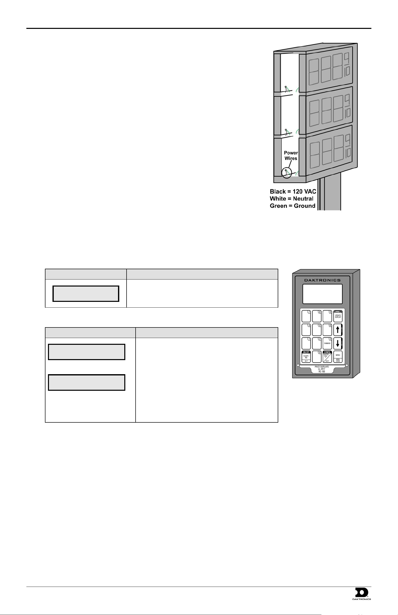
Power Installation
1. Open each display and locate the power harness (pigtail) inside.
2. Open one of the knockouts to be used for power connection Place a fitting in the knockout
opening to cover sharp edges.
3. Route the end of the power harness out the knockout (Figure 7).
4. Connect the wires from each display to the main power cable according to local and national
electrical codes.
5. Terminate power to a dedicated 120 VAC circuit. Consult the display specifications to ensure
that this circuit is adequate for the specific displays.
Note: It is required that this circuit not be linked to the building’s energy management system.
6. Turn power on and watch for boot-up sequence. After bootup, each display should show
“E4,” noting that the display has power but no message is currently stored on the driver.
Figure 7: Power Installation
Transmitter Use
After power and signal installation, make sure that the function switch on the radio is set to function three. Also make note of the radio address.
Then set up the transmitter (pictured in Figure 8) by using the following steps. These steps only need to be performed the first time the controller
is powered up and after it has completed its bootup.
LCD Screen Action
SELECT FUNCTION
GAS PRICE ↓↑
To set petroleum prices, follow these steps:
LCD Screen Action
• Press the arrow up or down keys<↑ ↓> until the gas price
• It will then go into Initializing Display.
LINE PRICE
1 ↓ $1.23 9/10
<EDIT> TO MODIFY
1 ↓ $1.23 9/10
For additional information on using the transmitter, refer to the display manual.
option is shown. Press the [Enter] key to accept.
• The display will toggle between these two screens.
• Press the up or down arrow keys <↑ ↓> to scroll through
the current setting for any of the lines on the display.
• Press the [Enter/Edit] key to modify any of the line
settings.
• Press any of the number keys to edit the price value for this
line.
• Press [Enter] to accept the new value or press [Clear] to
abort the changes.
• Press [Update Display] to send the values to the di splay.
Figure 8: Transmitter
DD1399078-Rev0 PO Box 5128, 201 Daktronics Drive, Brookings, SD 57006
27 August 2008 Tel: 866-343-3122 Fax: 605-697-4444
 Loading...