

Page 1
Fuelight™ FL-3000 and FL-4500
Line-to-Line Cable Installation Page 1 of 2
Additional Information
To watch a video about installing the line-to-line cable with drain wire, go to http://
www.youtube.com/watch?v=hhQXzGLpxMw
Display Interconnections
Signal travels from the host driver jack J9 to additional display
drivers through the Line-to-Line cable. Line-to-line connections are made using jacks
J9 and J10 on the driver.
The preferred cable routing has signal leaving each driver from jack J9
and entering the next driver on jack J10
Each time you connect the line-to-line cable to J9, you must also
connect the drain wire to the upper-left stud that holds the driver in
place.
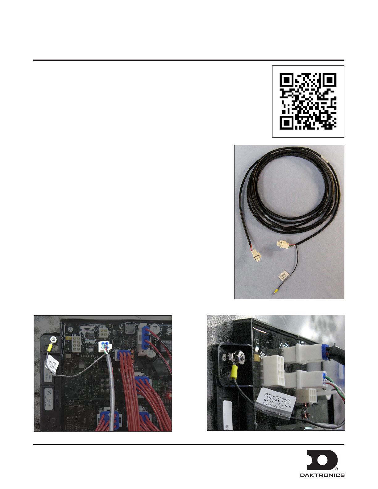
1. Connect the provided line-to-line cable, shown in Figure 1, to
host driver jack J9. The host driver can be identified by having
the communication option attached to jack J16.
2. Place the drain wire of the line-to-line cable on the upper-left
stud that holds the driver in place, as shown in Figure 2.
3. Place the 6-32 nut on the stud and tighten it with a 5/16" nut
driver, as shown in Figure 3.
Figure 1: Line-to-Line Cable
Figure 2: Installed Line-to-Line Cable with Drain Wire
DD2739343 Rev 00
21 February 2014
PO Box 5128 201 Daktronics Drive, Brookings, SD 57006-5128
tel: 800-325-8766 fax: 605-697-4700
Figure 3: Installed Drain Wire
www.daktronics.com
Page 2
Fuelight™ FL-3000 and FL-4500
Line-to-Line Cable Installation Page 2 of 2
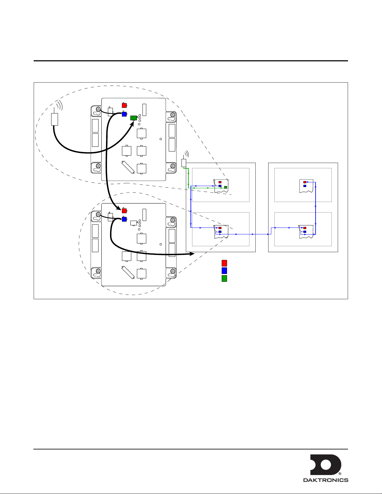
4. Route the provided line-to-line cable from the host driver jack J9 to the next client display driver,
connecting to jack J10, as shown in Figure 4.
J10
LINE TO LINE
J9
J16
COMM
PORT
Face 1
Price 1
Host Driver - Comm Attached
J10
J9
Price 2
J10 - Line In
J9 - Line Out
J16 - Comm Port
Price 1
Price 2
Face 2
Figure 4: Line-to-Line Cable Installation
5. Run cable through the knockouts located on the display’s backsheet and be sure to use the provided cable
bushings that snap into place.
6. Repeat until all displays are connected.
Note: Do not connect the last display driver back to the host.
Important Notes:
• Route cables at least 6 inches away from interfering sources like ballasts, florescent light bulbs, power
sources, any type of motor, etc.
• Pull excess cable into the display cabinet, coil cable, zip tie it together and carefully place coil inside the
display cabinet.
DD2739343 Rev 00
21 February 2014
PO Box 5128 201 Daktronics Drive, Brookings, SD 57006-5128
tel: 800-325-8766 fax: 605-697-4700
www.daktronics.com
 Loading...