

Page 1
201 Daktronics Drive PO Box 5128 Brookings, SD 57006-5128
Tel: 1-800-DAKTRONICS (1-800-325-8766) Fax: 605-697-4746
www.daktronics.com/support
Modular LED Football
Scoreboards
Installation Manual
DD2363266 Rev 2 – 5 December 2013
Model Series
FB-2500
FB-2600
Page 2

Page 3

DD2363266
Product 1647
Rev 2 – 5 December 2013
DAKTRONICS, INC.
Copyright 2012-2013
All rights reserved. While every precaution has been taken in the preparation of this manual, the publisher
assumes no responsibility for errors or omissions. No part of this book covered by the copyrights hereon may be
reproduced or copied in any form or by any means – graphic, electronic, or mechanical, including photocopying,
taping, or information storage and retrieval systems – without written permission of the publisher.
All Sport® and PanaView® are trademarks of Daktronics, Inc. Other trademarks used in this manual are the property of their
respective owners.
Page 4

Page 5

Table of Contents
Section 1: Introduction ............................................................................................................................ 1
1.1 Scoreboard Controllers ........................................................................................................... 1
Sport Codes ....................................................................................................................... 1
1.2 Troubleshooting ...................................................................................................................... 2
1.3 Specifications Label................................................................................................................. 2
1.4 Resources .................................................................................................................................. 2
1.5 Product Safety Approval........................................................................................................ 2
Section 2: Mechanical Installation ........................................................................................................ 3
2.1 Lifting the Scoreboard ............................................................................................................ 3
2.2 Scoreboard Mounting ............................................................................................................. 4
I-Beam Clamps ................................................................................................................. 5
Clamping Angles ............................................................................................................. 6
Mounting Tubes ............................................................................................................... 6
2.3 Ad Panel Mounting................................................................................................................. 7
Unistrut Attachment ........................................................................................................ 7
I-Beam Clamps ................................................................................................................. 8
Clamping Angles ............................................................................................................. 9
2.4 Scoreboard Protective Devices .............................................................................................. 9
Section 3: Electrical Installation .......................................................................................................... 11
3.1 Power ...................................................................................................................................... 11
Grounding ....................................................................................................................... 11
Connection ...................................................................................................................... 12
3.2 Power-On Self-Test (POST) ................................................................................................. 13
Radio Settings ................................................................................................................. 13
3.3 Signal Connection ................................................................................................................. 13
Fiber Optic ...................................................................................................................... 14
3.4 Power/Signal Connections Between Sections ................................................................... 14
3.5 Lightning Protection ............................................................................................................. 16
Section 4: Daktronics Exchange and Repair & Return Programs .................................................. 17
4.1 Exchange Program ................................................................................................................ 17
Before Contacting Daktronics....................................................................................... 17
4.2 Repair & Return Program .................................................................................................... 18
Shipping Address .......................................................................................................... 18
4.3 Daktronics Warranty and Limitation of Liability ............................................................. 18
Section 5: Scoreboard Options ............................................................................................................. 19
5.1 Team Name Message Centers (TNMCs) ............................................................................ 19
5.2 Trumpet Horns ...................................................................................................................... 19
5.3 Radio Control......................................................................................................................... 19
5.4 Changeable Caption Kits...................................................................................................... 20
Appendix A: Specifications ........................................................................................................................ 21
Appendix B: Reference Drawings ............................................................................................................ 23
Appendix C: Daktronics Warranty and Limitation of Liability .......................................................... 25
Table of Contents i
Page 6

Page 7

Sport
Common Code(s)
All Sport 5000
Baseball
5601 (with clock)
5602 (without clock)
Football
6601
Lacrosse/
Field Hockey
4601
Soccer
7601
Track
8601 (manual timing)
Section 1: Introduction
This manual explains the installation of Daktronics Modular LED Football Scoreboards (Product 1647).
For additional information regarding the safety, installation, operation, or service of this system, refer
to the telephone numbers listed in Section 5. This manual is not specific to a particular installation.
IMPORTANT SAFEGUARDS:
Please read and understand all instructions before beginning the installation process.
Do not drop control equipment or allow it to get wet.
Do not disassemble control equipment or electronic controls of the display; failure to
follow this safeguard will make the warranty null and void.
Disconnect display power when not in use or when servicing.
Disconnect display power before servicing power supplies to avoid electrical shock.
Power supplies run on high voltage and may cause physical injury if touched while
powered.
Do not modify the scoreboard structure or attach any panels or coverings to the
scoreboard without the express written consent of Daktronics, Inc.
Project-specific information takes precedence over any other general information found in
this manual. Such information may include:
Shop Drawings – describe mounting methods and locations of display components
and structural elements
System Risers – describe power and signal connections between display components
and the control location; may also include control room layout and schematic
Ensure all applicable material has been gathered before beginning the installation. Contact a
Daktronics sales coordinator or project manager.
1.1 Scoreboard Controllers
Daktronics outdoor scoreboards are designed for use with the All Sport® 5000 series control
consoles. This console uses keyboard overlays (sport inserts) to control numerous sports and
scoreboard models. Refer to the following manual for operating instructions:
All Sport 5000 Series Control Console Operation Manual (ED-11976)
The scoreboard controller manual is available online at www.daktronics.com/manuals.
Sport Codes
At right is a table of common sport codes for the
multiple modes of the football scoreboards in
this manual. Refer to the Operation Manuals for
a complete listing of sport codes.
Introduction 1
Page 8
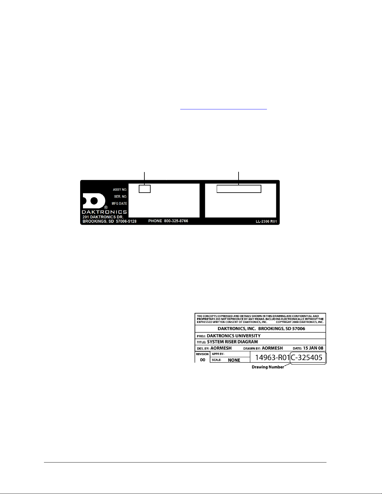
Figure 1: Specifications Label
Figure 2: Daktronics Drawing Label
0A-1647-0093 HRev: 01
SN: 1001
10/16/13
3219728 0001
FB-2500-200X
VOLTS: 120V AC
AMPS: 2.5
WATTS: 300
Product Number
Model Number
1.2 Troubleshooting
For an extensive troubleshooting guide and instructions on how to replace scoreboard
components, refer to the following manual:
Outdoor LED Scoreboards Service Manual (DD2124597)
The service manual is available online at www.daktronics.com/manuals.
1.3 Specifications Label
Power specifications as well as serial and model number information can be found on an ID
label on the display, similar to the one shown in Figure 1.
Please have the assembly number, model number, and the date manufactured on hand when
calling Daktronics customer service to ensure the request is serviced as quickly as possible.
Knowing the facility name and/or job number will also be helpful. Note that the Product
Number(s) are sometimes used to distinguish different generations of the scoreboards having
the same model number.
1.4 Resources
Figure 2 illustrates a Daktronics drawing
label. The drawing number is located in the
lower-right corner of a drawing. This
manual refers to drawings by listing the last
set of digits and the letter preceding them.
In the example, the drawing would be
referred to as Drawing C-325405.
Daktronics identifies manuals by the DD or
ED number located on the cover page of each manual. For example, this manual would be
referred to as DD2363266.
1.5 Product Safety Approval
Daktronics outdoor scoreboards are ETL listed and tested to CSA standard for outdoor use.
Contact Daktronics with any questions regarding testing procedures.
2 Introduction
Page 9
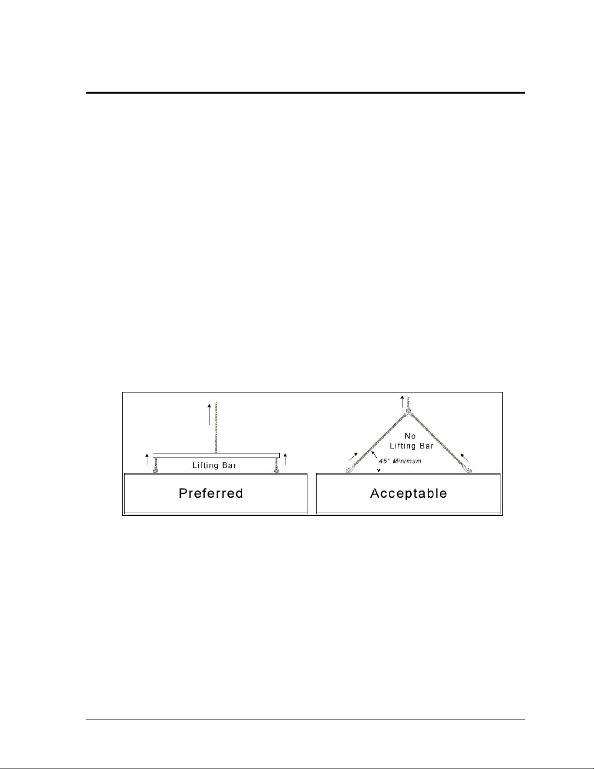
Figure 3: Lifting Methods
Section 2: Mechanical Installation
Mechanical installation consists of installing concrete footing and steel beams and mounting the
scoreboard and accompanying ad panels to the beams. Refer to site-specific diagrams for proper
placement and mounting method of display pieces. These drawings may be requested from a
Daktronics sales coordinator or project manager.
Be sure that the installation complies with local building codes and is suitable for the particular soil
and wind conditions. The columns, footings, and all connection details must be designed and certified
by a professional engineer licensed to practice in the state of the scoreboard installation.
Note: Daktronics does not assume any liability for any installation derived from the information
provided in this manual or installations designed and installed by others.
2.1 Lifting the Scoreboard
Larger scoreboard sections and message centers are shipped equipped with eyebolts used to
lift them. The eyebolts are located along the top of the cabinet for each scoreboard or
scoreboard section. Daktronics scoreboards use 1/2" and 5/8" shoulder-type eyebolts mounted
to the top of each scoreboard section.
Daktronics strongly recommends using a spreader bar, or lifting bar, to lift the display.
Spreader bars ensure the force on the eyebolts remains straight up, minimizing lifting stress.
Figure 3 illustrates the preferred scoreboard lifting method on the left and an acceptable
alternative lifting method on the right. When lifting the display:
Use a spreader bar if possible.
Use every lifting point provided.
Cables and chains attached to the eyebolts and directly to a center lifting point, as shown in
the right-hand example in Figure 3, can create a dangerous lateral force on the eyebolts and
may cause the eyebolts to fail. The smaller the angle between the cable and the top of the
display, the lighter the sign must be to safely lift it. If this method must be used, ensure a
minimum angle between the chain and scoreboard of at least 45°.
Mechanical Installation 3
Page 10
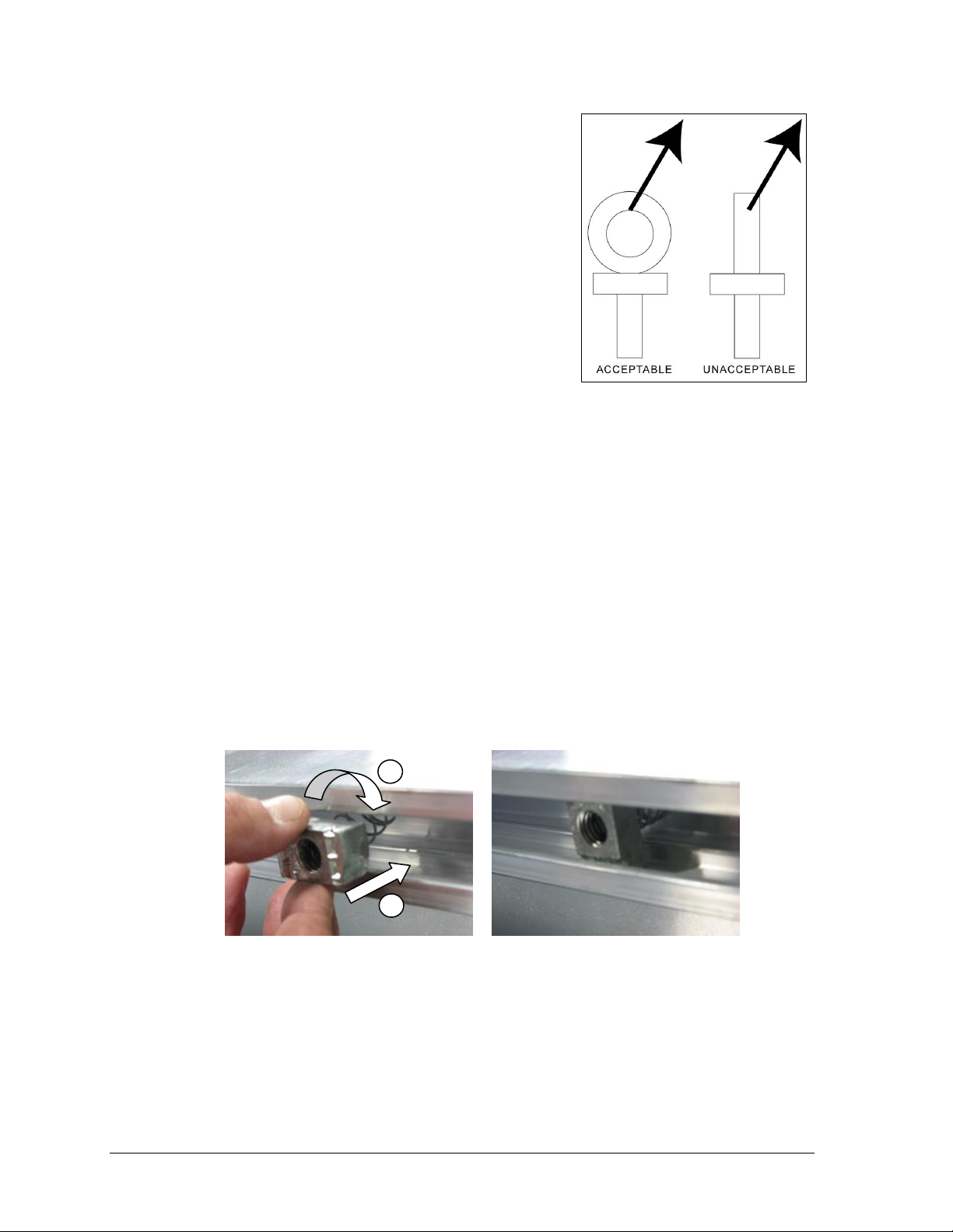
Figure 4: Eyebolt Plane Load
1) Insert into channel 2) Twist Correct spring nut position
Figure 5: Spring Nut Insertion
1
2
Do NOT attempt to lift the display if the angle is less than
45°. Exceeding load angles or weight limits could cause
the bolts in the scoreboard cabinet to buckle, resulting in
serious damage to the scoreboard or injury to personnel.
Also, loads should be applied directly in the plane of the
eyebolt as shown in Figure 4.
Note: Daktronics assumes no liability for damages
resulting from incorrect setup or lifting methods.
Eyebolts are intended for lifting only. Do not attempt
to permanently support the display by the eyebolts.
In typical multi-section installations, the lower scoreboard
is installed first and secured to the support beams.
The upper section is then placed atop or above the lower
section and attached to the beams. Refer to Section 3.4 for
more information on the power/signal connections between sections.
If installers remove the eyebolts, plug the holes with bolts and the rubber washers that are
used with the eyebolts. Apply silicone or another waterproof sealant to the eyebolt openings.
Also inspect the top and sides of the display for any other holes or openings that may allow
moisture to enter the display and plug and seal those openings.
2.2 Scoreboard Mounting
Three standard mounting methods are available for Daktronics modular football scoreboards.
Each method requires spring nuts to be inserted into the rear channel of the scoreboard:
1. Insert spring nuts into the top and bottom scoreboard channels. Twist the spring nuts
until they are perpendicular to the scoreboard channel (Figure 5).
Note: Each scoreboard section require four spring nuts per beam (two at the top and two
at the bottom).
2. Measure the beam spacing and position a spring nut on either side of the beams.
Once the spring nuts are in place, refer to the appropriate section below for the type of
mounting hardware provided with the scoreboard.
4 Mechanical Installation
Page 11
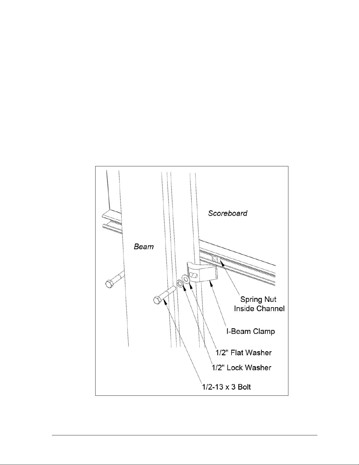
Figure 6: I-beam Clamp Mounting Method, Rear Isometric View
I-Beam Clamps
This mounting method is used to mount a scoreboard to I-beams with a flange thickness of
1
/4" – 3/4". If flange thickness is greater than 3/4", longer bolts will be required at additional
expense.
Mounting hardware includes I-beam clamps, 1/2-13 x 3" bolts, 1/2" flat washers, and 1/2" lock
washers. Refer to Figure 6 and Drawing A-1052565 in Appendix B.
1. Position a scoreboard section at the front of the beams, and lift it to the desired height.
2. Slide a lock washer, flat washer, and I-beam clamp onto the bolt, and loosely screw
the bolt into the spring nut.
3. Position each I-beam clamp assembly as close to the I-beam flanges as possible.
4. Make final adjustments in the positioning of the scoreboard section to ensure it is
flush and level, and firmly tighten all of the bolts.
5. Repeat steps 1-4 with all scoreboard sections.
Mechanical Installation 5
Page 12
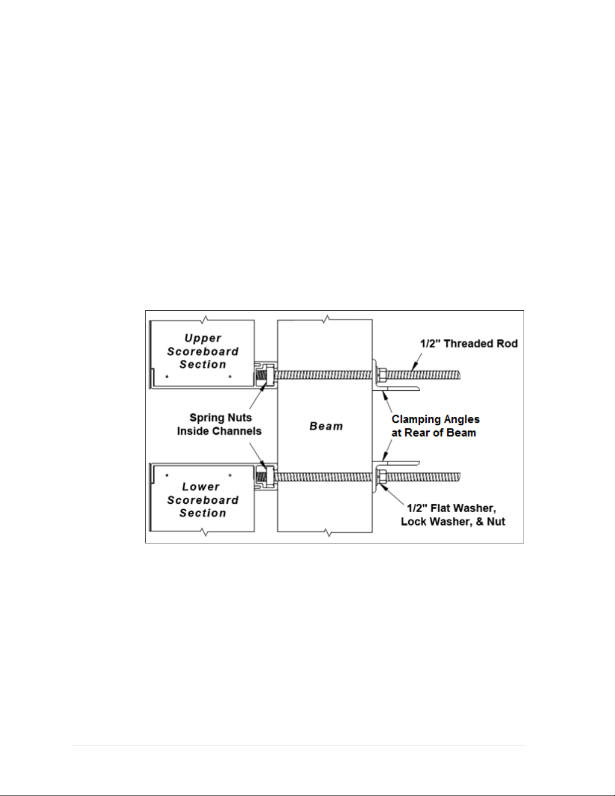
Figure 7: Clamping Angle Mounting Method, Side View
Clamping Angles
This mounting method may be used to mount a scoreboard to I-beams or any beam/pole that
does not have flanges.
Mounting hardware includes rear clamping angles; 1/2-13 x 24" threaded rods; and 1/2" nuts,
flat washers, and lock washers. Refer to Figure 7 and Drawing A-1048184 in Appendix B.
Note: The threaded rods do not pass through the beams; they run along both sides.
1. Screw a threaded rod into each of the spring nuts as far as it will go.
2. Position a scoreboard section at the front of the beams with the threaded rods
extending from the rear of the spring nuts, straddling the beams.
3. Lift the scoreboard section to the desired height.
4. Slide clamping angles over the ends of the rods and loosely install the washers and nuts.
5. Make final adjustments in the positioning of the scoreboard section to ensure it is
flush and level, and firmly tighten all of the 1/2" hex nuts.
6. Repeat steps 1-5 for all scoreboard sections.
Mounting Tubes
This mounting method may be used to mount a scoreboard to horizontal beams. The
mounting tubes are attached to the scoreboard using spring nuts and 1/2" hardware as
described above; this may be done during manufacturing or on-site. Refer to Figure 8 and
Drawing A-1048268 in Appendix B for mounting tube assembly. The clip angles can be
adjusted vertically before they are bolted or welded to the horizontal beams. Recommended
attachment method and positioning of display pieces are provided in site-specific diagrams.
6 Mechanical Installation
Page 13
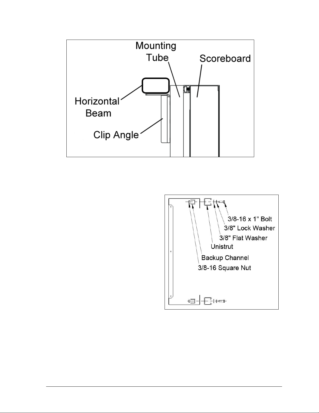
Figure 8: Mounting Tube Attachment, Side View
Figure 9: Unistrut Attachment, Side View
2.3 Ad Panel Mounting
Unistrut Attachment
1. Using the backup channel as a
template, drill four 7/16" holes in
the upper and lower rear flanges
of the ad panel where the beams
will be located.
Note: Try to ensure that the two
center holes will be within the
width of the beam.
2. If the ad panel has backsheets,
remove them as needed to
access the ad panel interior.
3. Attach the piece of unistrut to
the ad panel with the included
hardware, as shown in Figure 9.
4. If any backsheets were removed,
put them back on at this time.
5. Place spring nuts into the unistrut. Twist the spring nuts until they are perpendicular
to the unistrut channel (refer to Figure 5 from Section 2.2).
Once the unistrut is attached and the spring nuts are in place, refer to the appropriate section
below for the type of mounting hardware provided with the ad panel.
Mechanical Installation 7
Page 14
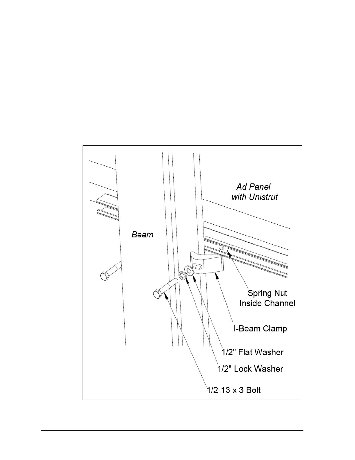
Figure 10: Ad Panel Mounting with I-beam Clamps, Rear Isometric View
I-Beam Clamps
Mounting hardware includes I-beam clamps, 1/2-13 x 3" bolts, 1/2" flat washers, and 1/2" lock
washers. Refer to Figure 10 and Drawing A-1052539 in Appendix B.
Note: I-beams must have a flange thickness of 1/4" – 3/4". If flange thickness is greater
than 3/4", longer bolts will be required at added expense.
1. Position the ad panel at the front of the beams, and lift it to the desired height.
2. Slide a lock washer, flat washer, and I-beam clamp onto the bolt, and loosely screw
the bolt into the spring nut.
3. Position each I-beam clamp assembly as close to the I-beam flanges as possible.
4. Make final adjustments in the positioning of the ad panel to ensure it is flush and
level, and firmly tighten all of the bolts.
8 Mechanical Installation
Page 15
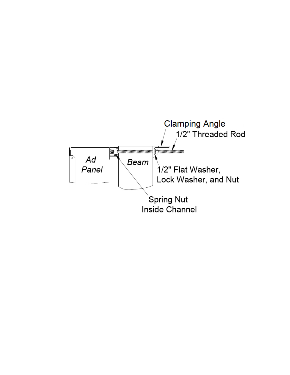
Figure 11: Ad Panel Mounting with Clamping Angles, Side View
Clamping Angles
Mounting hardware includes rear clamping angles; 1/2-13 x 24" threaded rods; and 1/2" nuts,
flat washers, and lock washers. Refer to Figure 11 and Drawing A-1052388 in Appendix B.
Note: The threaded rods do not pass through the beams; they run along both sides.
1. Screw a threaded rod into each of the spring nuts as far as it will go.
2. Position the scoreboard at the front of the beams, and lift it to the desired height.
3. Slide clamping angles over the ends of the rods and loosely install the washers and nuts.
4. Make final adjustments in the positioning of the ad panel to ensure it is flush and
level, and firmly tighten all of the 1/2" hex nuts.
2.4 Scoreboard Protective Devices
Daktronics makes optional protective devices, including screens and netting, to help prevent
damage to the scoreboard due to normal ball impacts.
Note: Some users install devices to protect the scoreboard from projectiles. Scoreboard
protection devices not provided by Daktronics must be approved by Daktronics prior to
installation. Failure to follow this approval procedure will void the scoreboard warranty.
Mechanical Installation 9
Page 16

Page 17

Section 3: Electrical Installation
CAUTION: Only qualified individuals should terminate power and signal cable and access the
electrical components of the display and its associated equipment. It is the responsibility of the
electrical contractor to ensure that all electrical work meets or exceeds local and national codes.
Daktronics engineering staff must approve all changes or the warranty will be void.
3.1 Power
Correct power installation is imperative for proper display operation. The subsections that
follow give details of display power installation. Only qualified individuals should attempt to
complete the electrical installation; untrained personnel should not attempt to install these
displays or any of the electrical components. Improper installation could result in serious
damage to the equipment or injury to personnel.
Multi-section outdoor scoreboards require a dedicated 120 V (or 240 V for international use)
circuit for incoming power (refer to Appendix A). The display itself has no breakers or fuses.
WARNING: It is critical that 120 V scoreboard circuits be fused at 20 A and that all
conductors used must be designed to pass a 20 A current in normal operation. For 240 V
scoreboards, consult local electrical codes. Failure to meet wiring and overcurrent
protection device requirements will void the scoreboard warranty.
Grounding
The display must be properly grounded according to local and national codes or the warranty
will be void. Proper grounding is necessary for reliable equipment operation and protects the
equipment from damaging destructive disturbances and lightning.
Daktronics recommends a resistance-to-ground of 10 ohms or less. The electrical contractor
performing the electrical installation can verify ground resistance. Daktronics Sales and
Service personnel can also provide this service.
The display system must be earth-ground. The material for an earth-ground electrode differs
from region to region and may vary according to conditions present at the site. Consult local
and national electrical codes.
Daktronics does not recommend using the support structure as an earth-ground electrode;
concrete, primer, corrosion, and other factors make the support structure a poor ground.
Note: The support structure may be used as an earth-ground electrode only if designed to
do so. A qualified inspector must approve the support structure and grounding methods.
There are two types of power installation: installation with ground and neutral conductors
provided, and installation with only a neutral conductor provided. These two power
installations differ slightly, as described in the following paragraphs:
Electrical Installation 11
Page 18

Figure 12: Power Warning Label
Figure 13: Driver Enclosure & Main Terminal Block
Installation with Ground and Neutral Conductors Provided
For this type of installation, the power circuit must contain an isolated earth-ground
conductor. In this circumstance, do not connect neutral to ground at the disconnect or at the
display as this would violate electrical codes and void the warranty.
Use a disconnect so that all ungrounded lines can be disconnected. The National Electrical
Code requires the use of a lockable power disconnect within sight of or at the display.
Installation with Only a Neutral Conductor Provided
Installations where no grounding conductor is provided must comply with Article 250-32 of
the National Electrical Code. If the installation in question meets all of the requirements of
Article 250-32, the following guidelines must be observed:
Connect the grounding electrode cable at the local disconnect, never at the display
driver/power enclosure.
Use a disconnect that opens all of the ungrounded phase conductors.
Connection
Both power and signal cables are routed into the scoreboard from the rear via conduit.
All power and signal wiring terminates at the master driver enclosure.
Look for a warning label similar to Figure 12 to locate
the access panel to the driver enclosure. Remove the
screws or loosen the latches to open the access door
panel. Remove the metal cover of the driver enclosure to
expose the driver components (Figure 13).
Connect the appropriate wires coming through the rear of the scoreboard to the main
terminal block, as shown in Figure 13. Note that SIGNAL OUT connects here as well.
12 Electrical Installation
Page 19

Figure 14: Digit Segment POST
Figure 15: Signal Surge Arrestor Card
Certain scoreboard sections do not receive power via terminal block. Instead, an interconnect
harness routes from the nearest scoreboard section. Refer to Section 3.4.
Note: If a power receptacle is needed to operate the control console at the scoreboard for
troubleshooting, Daktronics recommends that an installation electrician provides a 120 V
outlet close to the disconnect box specifically for this purpose.
3.2 Power-On Self-Test (POST)
The scoreboard performs a self-test each time that power is turned on and the control console
is powered off or not attached to the scoreboard. If the control console is attached and
powered on, the self-test does not run, and data from the control console is displayed on the
scoreboard after a brief period of time. Each scoreboard self-test pattern will vary depending
on the scoreboard model, the number of drivers and types of digits. Figure 14 shows an
example of the LED bar test pattern that each digit performs.
Radio Settings
If a radio receiver is installed, the radio Broadcast settings (“b1”) and Channel settings (“C1”)
will be displayed in the clock digits during the POST. These values must match the settings in
the control console (refer to the manual listed in Section 1.1).
3.3 Signal Connection
For wired setups, route signal cable from the
control location into the conduit knockout on
the rear of the scoreboard to the signal surge
arrestor card (Figure 15), located just above the
main termination block in the driver enclosure.
At the SIGNAL IN terminal block, connect red
signal wire to positive (+) and black signal wire
to negative (–).
Note: Be sure to properly connect the
shield (silver) wire to the SHIELD terminal.
To connect signal to additional scoreboard sections, route signal wire from SIGNAL OUT on
the main terminal block (Figure 13) of one section to SIGNAL IN on the signal card of another.
For signal cable, Daktronics recommends, as a minimum, single-pair, shielded cable, 22 AWG
(part # W-1077). Two-pair shielded cable (part # W-1234) is preferred.
Electrical Installation 13
Page 20

Information
Shown
Model #
Driver/Power
Supply Location
Power/Signal
Connections*
T.O.L. (HOME)
FB-2531, FB-2533, FB-2536,
FB-2538, FB-2540, FB-2545
HOME Score
A1 J1
PS1 J1
A1 J50
T.O.L. (GUEST)
FB-2571, FB-2573, FB-2575,
FB-2577, FB-2579, FB-2583
GUEST Score
A1 J10
PS1 J10
A1 J50
DOWN
FB-2618, FB-2628, FB-2658
TO GO
A1 J3
PS1 J3
A1 J42B
Mod 1 J2
QTR (quarter)
FB-2621, FB-2631, FB-2661
BALL ON
A1 J8
PS1 J8
A1 J42B
Mod 4 J1
Figure 16: Driver Fiber
Connection Location
Fiber Optic
Another common signal communication method is fiber optic
cabling. A minimum cabling of multi-mode, 62.5/125 um, and 2core fiber cable is recommended (part # W-1242). The fiber optic
cable is terminated to a male ST-type connector and plugged into
the mating J26 FIBER jack on the driver (Figure 16). This method
requires a signal converter between the All Sport console’s
scoreboard output and the fiber optic cable (not provided by
Daktronics).
3.4 Power/Signal Connections Between Sections
The table below lists the scoreboard sections that do not receive main power or signal:
The T.O.L., DOWN, and QTR sections may have up to four connections:
14 Electrical Installation
* For HOME T.O.L. sections built prior to September 2013, the digit connects to J14 on
A1/PS1. For GUEST T.O.L. sections, the digit connects to J15 on A1/PS1. Backlit/
electronic captions for either section connect to J42B.
Route the 9-pin plug into the adjacent section and connect to the appropriate jack on
the primary (A1) driver.
Route the 2-pin plug into the adjacent section and connect to the appropriate jack on
the Power Supply (24"+ white LED digits or 36"+ red/amber LED digits only).
If the section includes a backlit or electronic caption, a 5-pin plug must be connected
to the power/signal interconnect cable coming from the primary (A1) driver.
A ribbon cable must be connected between the last mod of the DOWN and BALL ON
electronic captions to the first mod of the TO GO and QTR electronic captions.
Page 21

Figure 17: T.O.L. Power/Signal Interconnections (Front View)
Figure 18: BALL ON/QTR Power/Signal Interconnections (Front View)
DOWN/ TO GO
sections are reversed.
Refer to Figure 17 for internal power/signal connection guidelines between a T.O.L. section
and its mating HOME/GUEST section.
Refer to Figure 18 for internal power/signal connection guidelines between DOWN/TO GO
and BALL ON/QTR sections.
Electrical Installation 15
Page 22

Figure 19: Re-driving Signal (Rear View)
For sections that are too far apart to use internal interconnects, the signal may be re-driven, or
“daisy-chained”. Typically, the Game Clock section would receive primary signal from the
control location, and signal cable could then branch out to the HOME score and GUEST score
sections. From there, signal can be re-driven once more to the DOWN/TO GO and BALL
ON/QTR sections. Refer to Figure 19 for an example of re-driving signal.
Note: For radio-controlled systems, the radio receiver may be located in one section,
while signal cable is routed to the other sections as needed.
3.5 Lightning Protection
The use of a disconnect near the scoreboard to completely cut all current-carrying lines
significantly protects the circuits against lightning damage. In order for this system to
provide protection, the power must be disconnected when the scoreboard is not in use.
The control console should also be disconnected from power and from the signal junction box
when the system is not in use. The same surges that may damage the scoreboard’s driver can
also damage the console’s circuitry.
16 Electrical Installation
Page 23

Market Description
Customer Service Number
Schools (including community/junior colleges), religious
organizations, municipal clubs and community centers
877-605-1115
Universities and professional sporting events, live events
for auditoriums and arenas
866-343-6018
Section 4: Daktronics Exchange and Repair &
Return Programs
4.1 Exchange Program
The Daktronics Exchange Program is a service for quickly replacing key components in need
of repair. If a component fails, Daktronics sends a replacement part to the customer who, in
turn, returns the failed component to Daktronics. This decreases equipment downtime.
Customers who follow the program guidelines explained below will receive this service.
Before Contacting Daktronics
Identify these important numbers:
Display Serial Number: _________________________________________________________
Display Model Number: _________________________________________________________
Job/Contract Number: __________________________________________________________
Date Installed: _________________________________________________________________
Daktronics Customer ID Number: ________________________________________________
To participate in the Exchange Program, follow these steps:
1. Call Daktronics Customer Service.
2. When the exchange part is received, mail the old part to Daktronics.
If the replacement part fixes the problem, send in the problem part being replaced.
a. Package the old part in the same shipping materials in which the replacement
part arrived.
b. Fill out and attach the enclosed UPS shipping document.
c. Ship the part to Daktronics.
3. The defective or unused parts must be returned to Daktronics within 5 weeks of
initial order shipment.
If any part is not returned within five (5) weeks, a non-refundable invoice will be
presented to the customer for the costs of replenishing the exchange parts inventory
with a new part.
Daktronics reserves the right to refuse parts that have been damaged due to acts of
nature or causes other than normal wear and tear.
Daktronics Exchange and Repair & Return Programs 17
Page 24

4.2 Repair & Return Program
For items not subject to exchange, Daktronics offers a Repair & Return Program. To send a
part for repair, follow these steps:
1. Call or fax Daktronics Customer Service:
Refer to the appropriate market phone number in the chart on the previous page.
Fax: 605-697-4444
2. Receive a case number before shipping.
This expedites repair of the part.
3. Package and pad the item carefully to prevent damage during shipment.
Electronic components, such as printed circuit boards, should be placed in an
antistatic bag before boxing. Daktronics does not recommend using packing ‘peanuts’
when shipping.
4. Enclose:
name
address
phone number
the case number
a clear description of symptoms
Shipping Address
Daktronics Customer Service
[Case #]
201 Daktronics Drive, Dock E
Brookings, SD 57006
4.3 Daktronics Warranty and Limitation of Liability
The Daktronics Warranty and Limitation of Liability is located in Appendix C. The Warranty
is independent of Extended Service agreements and is the authority in matters of service,
repair, and display operation.
18 Daktronics Exchange and Repair & Return Programs
Page 25

Section 5: Scoreboard Options
5.1 Team Name Message Centers (TNMCs)
Team Name Message Centers (TNMCs) are programmable LED displays that allow users to
show custom Home and Guest names. TNMCs are typically ordered factory-installed but can
be field-mounted after the scoreboard is in place.
For more information about TNMCs, contact a Daktronics representative or refer to the
service manual listed in Section 1.2.
5.2 Trumpet Horns
Trumpet horn options are available for installation only on scoreboards that have clocks.
There are two types of optional trumpet horns:
Internally mounted 120 V trumpet horn
Externally mounted 12 VDC trumpet horn
A 120 V trumpet horn cannot be installed on a 240 V model scoreboard. For more information
about trumpet horns, contact a Daktronics representative or refer to the Trumpet Horn
Installation Manual (ED-10006), available online at www.daktronics.com/manuals.
5.3 Radio Control
Radio control is an option for all Daktronics outdoor LED scoreboards. The system provides
scoreboard control via a 2.4 GHz, extra-high frequency FM signal.
The radio transmitter and receiver are not standard. This setup requires a control console
equipped with radio output as well as a radio receiver plugged into the primary driver and
mounted internally to the front panel of the scoreboard.
For additional information about this option, contact a Daktronics representative; for
complete information on setting up radio communication control, refer to the Gen V Radio
Installation Manual (ED-13831) or the Gen VI Radio Installation Manual (DD2362277),
both available online at www.daktronics.com/manuals.
Scoreboard Options 19
Page 26

Figure 20: Changing Scoreboard Captions
5.4 Changeable Caption Kits
Caption kits contain hardware for one caption
only and consist of an upper caption retainer,
a lower caption retainer, a changeable caption
panel and screws.
The standard HOME and GUEST captions
are applied directly to the face of the
scoreboard. Team name captions are on
changeable panels that fit into retainers
mounted above and below the HOME and
GUEST captions. If these retainers are not
already present, attach the retainers included
with the caption kit.
Other caption kits are available to show
different information for different sports.
To install a changeable panel:
1. Insert the screws on the caption changing pole (Daktronics part # 0F-1091-0099) into
the keyholes on the panel.
2. Lift the panel all the way up into the upper retainer and then insert the bottom of the
panel into the lower retainer (Figure 20).
3. Take the screws on the caption changing pole out of the keyholes.
Reverse this procedure to remove the caption panel.
The caption changer pole is extendable. Loosen the ring tightener and extend the pole to the
desired length, and then tighten the ring before lifting the caption.
CAUTION: The aluminum caption changer can conduct electricity. Do not use it within
20-feet of power lines. Also be careful when using the caption changer in high or gusting
winds. Wind may catch the panel and unhook it from the changer or make it difficult to
maintain a grip on the pole. Hold the pole tightly in windy conditions.
20 Scoreboard Options
Page 27

Appendix A: Specifications
Document Title Document Number
FB-2500 & FB-2600 Series Modular Football Scoreboards Specifications ........................... DD2216211
Specifications 21
Page 28

Page 29

FB-2501
FB-2611
FB-2573
FB-2572
FB-2501
FB-2532
FB-2610
HOME
T.O.L.
DOWN TO GO QTR
180x234
Video Display
GUEST
BALL ON
T.O.L.
FB-2572
FB-2573FB-2533
FB-2611
FB-2500 & FB-2600 SERIES MODULAR FOOTBALL SCOREBOARDS
SPECIFICATIONS
Designed to accompany Daktronics standard outdoor LED video displays, this versatile line of modular scoreboards provides an
endless variety of layout possibilities. They may also be used independently of a video display, such as for auxiliary scoreboards
along a section of narrow fascia. Select from numerous clock, home and guest score, and game information sections to
complement the video display and create a unique scoring system.
These football scoreboards feature amber, red or white PanaView® LED digits to display period time to 99:59, HOME and
GUEST scores to 99, T.O.L. (time outs left) to nine and DOWN/TO GO/BALL ON/QTR (quarter) information. Six-digit clocks can
display race time to 99:59.99. An arrow- or diamond-shaped group of LEDs indicates possession. When period time is less than
one minute, scoreboard displays time to 1/10 of a second. Digits can be dimmed for night viewing.
PRODUCT SAFETY
APPROVAL: ETL listed to UL Standards 48 and 1433. Tested to CSA standards and CE labeled for outdoor use.
CONSTRUCTION: Alcoa aluminum alloy 5052 for excellent corrosion resistance.
CAPTIONS: HOME and GUEST captions are available in three different sizes, depending on the model:
14" (356 mm), 15" (381 mm), and 18" (457 mm) high. All other captions are 12" (305 mm) high.
Models FB-2610 & FB-2611 use 8" (203 mm) captions. Standard captions are vinyl, applied directly
to the display face.
CABINET COLOR: More than 150 colors (from Martin Senour® paint book) are available at no additional cost.
OPERATING Display: -22 to 122 degrees Fahrenheit (-30 to 50 degrees Celsius)
TEMPERATURES: Console: 32 to 130 degrees Fahrenheit (0 to 54 degrees Celsius)
DD2216211 032213 Page 1 of 12
201 Daktronics Drive, PO Box 5128, Brookings, SD 57006
Phone: 1-800-325-8766 or 605-692-0200 Fax: 605-697-4746
www.daktronics.com E-mail: sales@daktronics.com
Page 30

FB-2500 & FB-2600 SERIES PRODUCT SPECIFICATIONS (CONTINUED)
FB-2507
FB-2510
FB-2508
FB-2511
CLOCK SECTIONS:
BASE
MODEL
FB-2500
FB-2501
FB-2502
FB-2503
FB-2504
FB-2505
FB-2506
FB-2507
FB-2508
FB-2509
FB-2510
FB-2511
FB-2513
DIMENSIONS
(height, width, depth)
H 3'-7.2", W 7'-2.4", D 8"
(1097 mm, 2195 mm, 203 mm)
H 3'-7.2", W 9'-7.2", D 8"
(1097 mm, 2926 mm, 203 mm)
H 3'-7.2", W 10'-9.6", D 8"
(1097 mm, 3292 mm, 203 mm)
H 4'-9.6", W 7'-2.4", D 8"
(1463 mm, 2195 mm, 203 mm)
H 4'-9.6", W 9'-7.2", D 8"
(1463 mm, 2926 mm, 203 mm)
H 4'-9.6", W 10'-9.6", D 8"
(1463 mm, 3292 mm, 203 mm)
H 3'-7.2", W 10'-9.6", D 8"
(1097 mm, 3292 mm, 203 mm)
H 3'-7.2", W 14'-4.8", D 8"
(1097 mm, 4389 mm, 203 mm)
H 3'-7.2", W 15'-7.2", D 8"
(1097 mm, 4755 mm, 203 mm)
H 4'-9.6", W 10'-9.6", D 8"
(1463 mm, 3292 mm, 203 mm)
H 4'-9.6", W 14'-4.8", D 8"
(1463 mm, 4389 mm, 203 mm)
H 4'-9.6", W 15'-7.2", D 8"
(1463 mm, 4755 mm, 203 mm)
H 4'-9.6", W 14'-4.8", D 8"
(1463 mm, 4389 mm, 203 mm)
UNCRATED
WEIGHT
130 lb
(59 kg)
173 lb
(79 kg)
195 lb
(89 kg)
173 lb
(79 kg)
231 lb
(105 kg)
260 lb
(118 kg)
195 lb
(89 kg)
260 lb
(118 kg)
281 lb
(128 kg)
260 lb
(118 kg)
346 lb
(157 kg)
375 lb
(170 kg)
346 lb
(157 kg)
POWER*
(Watts)
R/A = 300
W = 250
R/A = 300
W = 350
R/A = 200
W = 400
R/A = 300
W = 250
R/A = 300
W = 350
R/A = 200
W = 400
R/A = 300
W = 250
R/A = 300
W = 350
R/A = 350
W = 650
R/A = 300
W = 250
R/A = 300
W = 350
R/A = 350
W = 650
R/A = 350
W = 650
DIGIT SIZE
24" (610 mm)
30" (762 mm)
36" (914 mm)
24" (610 mm)
30" (762 mm)
36" (914 mm)
24" (610 mm)
30" (762 mm)
36" (914 mm)
24" (610 mm)
30" (762 mm)
36" (914 mm)
48" (1219 mm)
FB-2500
FB-2503
FB-2507
FB-2510
*Sections with 30" or smaller digits are shown with a max of 300 W. Sections with 36" or larger digits and all sections
with white digits include a 1000 W power supply and actual digit power consumption is shown.
FB-2501
FB-2504
FB-2508
FB-2511
FB-2502
FB-2505
FB-2506
FB-2509
FB-2513
DD2216211 032213 Page 2 of 12
201 Daktronics Drive, PO Box 5128, Brookings, SD 57006
Phone: 1-800-325-8766 or 605-692-0200 Fax: 605-697-4746
www.daktronics.com E-mail: sales@daktronics.com
Page 31

FB-2500 & FB-2600 SERIES PRODUCT SPECIFICATIONS (CONTINUED)
DOWN/TO GO & BALL ON/QTR SECTIONS:
BASE
MODEL
FB-2610
FB-2611
FB-2612
FB-2613
FB-2614
FB-2615
FB-2616
FB-2617
FB-2618
FB-2619
FB-2620
FB-2621
FB-2622
FB-2623
FB-2624
FB-2625
FB-2626
FB-2627
FB-2628
FB-2629
FB-2630
FB-2631
DIMENSIONS
(height, width, depth)
H 3'-7.2", W 7'-2.4", D 8"
(1097 mm, 2195 mm, 203 mm)
H 3'-7.2", W 7'-2.4", D 8"
(1097 mm, 2195 mm, 203 mm)
H 3'-7.2", W 16'-9.6", D 8"
(1097 mm, 5121 mm, 203 mm)
H 3'-7.2", W 16'-9.6", D 8"
(1097 mm, 5121 mm, 203 mm)
H 3'-7.2", W 16'-9.6", D 8"
(1097 mm, 5121 mm, 203 mm)
H 3'-7.2", W 16'-9.6", D 8"
(1097 mm, 5121 mm, 203 mm)
H 3'-7.2", W 16'-9.6", D 8"
(1097 mm, 5121 mm, 203 mm)
H 3'-7.2", W 16'-9.6", D 8"
(1097 mm, 5121 mm, 203 mm)
H 3'-7.2", W 9'-7.2", D 8"
(1097 mm, 2926 mm, 203 mm)
H 3'-7.2", W 9'-7.2", D 8"
(1097 mm, 2926 mm, 203 mm)
H 3'-7.2", W 9'-7.2", D 8"
(1097 mm, 2926 mm, 203 mm)
H 3'-7.2", W 9'-7.2", D 8"
(1097 mm, 2926 mm, 203 mm)
H 4'-9.6", W 8'-4.8", D 8"
(1463 mm, 2560 mm, 203 mm)
H 4'-9.6", W 8'-4.8", D 8"
(1463 mm, 2560 mm, 203 mm)
H 4'-9.6", W 9'-7.2", D 8"
(1463 mm, 2926 mm, 203 mm)
H 4'-9.6", W 9'-7.2", D 8"
(1463 mm, 2926 mm, 203 mm)
H 4'-9.6", W 16'-9.6", D 8"
(1463 mm, 5121 mm, 203 mm)
H 4'-9.6", W 16'-9.6", D 8"
(1463 mm, 5121 mm, 203 mm)
H 4'-9.6", W 9'-7.2", D 8"
(1463 mm, 2926 mm, 203 mm)
H 4'-9.6", W 9'-7.2", D 8"
(1463 mm, 2926 mm, 203 mm)
H 4'-9.6", W 9'-7.2", D 8"
(1463 mm, 2926 mm, 203 mm)
H 4'-9.6", W 9'-7.2", D 8"
(1463 mm, 2926 mm, 203 mm)
UNCRATED
WEIGHT
130 lb
(59 kg)
130 lb
(59 kg)
303 lb
(138 kg)
303 lb
(138 kg)
303 lb
(138 kg)
303 lb
(138 kg)
303 lb
(138 kg)
303 lb
(138 kg)
173 lb
(79 kg)
173 lb
(79 kg)
173 lb
(79 kg)
173 lb
(79 kg)
202 lb
(92 kg)
202 lb
(92 kg)
231 lb
(105 kg)
231 lb
(105 kg)
404 lb
(184 kg)
404 lb
(184 kg)
231 lb
(105 kg)
231 lb
(105 kg)
231 lb
(105 kg)
231 lb
(105 kg)
POWER*
(Watts)
R/A = 300
W = 150
R/A = 300
W = 150
R/A = 300
W = 150
R/A = 300
W = 150
R/A = 300
W = 150
R/A = 300
W = 150
R/A = 150
W = 300
R/A = 150
W = 300
(power from
FB-2620)
R/A = 150
W = 350
R/A = 150
W = 350
(power from
FB-2619)
R/A = 300
W = 150
R/A = 300
W = 150
R/A = 300
W = 150
R/A = 300
W = 150
R/A = 150
W = 300
R/A = 150
W = 300
(power from
FB-2630)
R/A = 150
W = 350
R/A = 150
W = 350
(power from
FB-2629)
DIGIT SIZE
24" (610 mm)
24" (610 mm)
24" (610 mm)
24" (610 mm)
30" (762 mm)
30" (762 mm)
36" (914 mm)
36" (914 mm)
36" (914 mm)
36" (914 mm)
36" (914 mm)
36" (914 mm)
24" (610 mm)
24" (610 mm)
30" (762 mm)
30" (762 mm)
36" (914 mm)
36" (914 mm)
36" (914 mm)
36" (914 mm)
36" (914 mm)
36" (914 mm)
DD2216211 032213 Page 3 of 12
201 Daktronics Drive, PO Box 5128, Brookings, SD 57006
Phone: 1-800-325-8766 or 605-692-0200 Fax: 605-697-4746
www.daktronics.com E-mail: sales@daktronics.com
Page 32

FB-2500 & FB-2600 SERIES PRODUCT SPECIFICATIONS (CONTINUED)
FB-2500
FB-2503
FB-2501
FB-2504
FB-2502
FB-2505
FB-2506
FB-2509
FB-2507
FB-2510
FB-2508
FB-2511
TO GO
DOWN
TO GO
DOWN
TO GO
DOWN
TO GO
DOWN
FB-2612
FB-2614
FB-2616
FB-2626
TO GO
DOWN
FB-2656 FB-2657
BASE
MODEL
FB-2656
FB-2657
FB-2658
FB-2659
FB-2660
FB-2661
*Sections with 30" or smaller digits are shown with a max of 300 W. Sections with 36" or larger digits and all sections with
white digits include a 1000 W power supply and actual digit power consumption is shown.
DOWN TO GO
(1463 mm, 5852 mm, 203 mm)
(1463 mm, 5852 mm, 203 mm)
(1463 mm, 3292 mm, 203 mm)
(1463 mm, 3292 mm, 203 mm)
(1463 mm, 3292 mm, 203 mm)
(1463 mm, 3292 mm, 203 mm)
FB-2610
DOWN TO GO
DIMENSIONS
(height, width, depth)
H 4'-9.6", W 19'-2.4", D 8"
H 4'-9.6", W 19'-2.4", D 8"
H 4'-9.6", W 10'-9.6", D 8"
H 4'-9.6", W 10'-9.6", D 8"
H 4'-9.6", W 10'-9.6", D 8"
H 4'-9.6", W 10'-9.6", D 8"
BALL ON
BALL ON
QTR
FB-2611
QTR
UNCRATED
WEIGHT
461 lb
(210 kg)
461 lb
(210 kg)
260 lb
(118 kg)
260 lb
(118 kg)
260 lb
(118 kg)
260 lb
(118 kg)
DOWN
TO GO
FB-2618
FB-2620
FB-2628
POWER
(Watts)*
R/A = 250
W = 500
R/A = 250
W = 500
(power from
FB-2660)
R/A = 300
W = 700
R/A = 300
W = 700
(power from
FB-2659)
BALL ON
DIGIT SIZE
48" (1219 mm)
48" (1219 mm)
48" (1219 mm)
48" (1219 mm)
48" (1219 mm)
48" (1219 mm)
FB-2619
QTR
FB-2621
FB-2629
FB-2622
DOWN TO GO
FB-2624
FB-2658
DOWN
TO GO
FB-2660
FB-2623
BALL ON
BALL ON
QTR
FB-2625
FB-2659
FB-2661
QTR
DOWN
TO GO
FB-2630
BALL ON
QTR
FB-2631
DD2216211 032213 Page 4 of 12
201 Daktronics Drive, PO Box 5128, Brookings, SD 57006
Phone: 1-800-325-8766 or 605-692-0200 Fax: 605-697-4746
www.daktronics.com E-mail: sales@daktronics.com
Page 33

FB-2508
FB-2511
FB-2513
FB-2500 & FB-2600 SERIES PRODUCT SPECIFICATIONS (CONTINUED)
HOME
HOMEHOME
GUEST
GUESTGUEST
DOWN
DOWN
DOWN
DOWN
DOWN
TO GO
FB-2612
TO GO
FB-2614
TO GO
FB-2616
TO GO
FB-2626
TO GO
FB-2656 FB-2657
BALL ON
FB-2613
BALL ON
FB-2615
BALL ON
FB-2617
BALL ON
FB-2627
BALL ON
QTR
QTR
QTR
QTR
QTR
DOWN TO GO DOWN TO GO DOWN TO GO
All DOWN/TO GO and BALL ON/QTR captions are
available in vinyl, backlit or electronic.
All sections are available with backlit or electronic captions in place of vinyl captions:
• One backlit caption adds 20 lb (9 kg) to overall weight and 150 W to overall power.
• One 8x32-34mm electronic caption adds 40 lb (18 kg) to overall weight and 150 W to overall power.
• Electronic caption LEDs are typically the same color as the LED digits on the other scoreboard sections.
• Backlit captions use 120 VAC circular uorescent bulbs.
With side-by-side DOWN/TO GO sections, DOWN will always be to the left of TO GO and they will both be
incorporated into one cabinet. When sections are stacked one on top of the other, the DOWN section will always
be above the TO GO section.
With side-by-side BALL ON/QTR sections, BALL ON will always be to the left of QTR and they will both be
incorporated into one cabinet. When sections are stacked one on top of the other, the BALL ON section will always
be above the QTR section.
DD2216211 032213 Page 5 of 12
201 Daktronics Drive, PO Box 5128, Brookings, SD 57006
Phone: 1-800-325-8766 or 605-692-0200 Fax: 605-697-4746
www.daktronics.com E-mail: sales@daktronics.com
Page 34

FB-2500 & FB-2600 SERIES PRODUCT SPECIFICATIONS (CONTINUED)
HOME SECTIONS:
BASE
MODEL
FB-2530
FB-2531
FB-2532
FB-2533
FB-2535
FB-2536
FB-2537
FB-2538
FB-2539
FB-2540
FB-2542
FB-2544
FB-2545
FB-2560
FB-2561
FB-2562
FB-2563
FB-2564
FB-2565
FB-2566
*Sections with 30" or smaller digits are shown with a max of 300 W. Sections with 36" or larger digits and all sections with
white digits include a 1000 W power supply and actual digit power consumption is shown.
(1463 mm, 2195 mm, 203 mm)
(1097 mm, 2195 mm, 203 mm)
(1463 mm, 2195 mm, 203 mm)
(1097 mm, 2195 mm, 203 mm)
(1097 mm, 2926 mm, 203 mm)
(1097 mm, 2926 mm, 203 mm)
(1463 mm, 2926 mm, 203 mm)
(1097 mm, 2926 mm, 203 mm)
(1463 mm, 2926 mm, 203 mm)
(1097 mm, 2926 mm, 203 mm)
(1463 mm, 2926 mm, 203 mm)
(1463 mm, 2926 mm, 203 mm)
(1097 mm, 2926 mm, 203 mm)
(1463 mm, 4389 mm, 203 mm)
(1463 mm, 4389 mm, 203 mm)
(1463 mm, 5121 mm, 203 mm)
(1463 mm, 5121 mm, 203 mm)
(1463 mm, 8778 mm, 203 mm)
(1097 mm, 8778 mm, 203 mm)
(1097 mm, 5121 mm, 203 mm)
DIMENSIONS
(height, width, depth)
H 4'-9.6", W 7'-2.4", D 8"
H 3'-7.2", W 7'-2.4", D 8"
H 4'-9.6", W 7'-2.4", D 8"
H 3'-7.2", W 7'-2.4", D 8"
H 3'-7.2", W 9'-7.2", D 8"
H 3'-7.2", W 9'-7.2", D 8"
H 4'-9.6", W 9'-7.2", D 8"
H 3'-7.2", W 9'-7.2", D 8"
H 4'-9.6", W 9'-7.2", D 8"
H 3'-7.2", W 9'-7.2", D 8"
H 4'-9.6", W 9'-7.2", D 8"
H 4'-9.6", W 9'-7.2", D 8"
H 3'-7.2", W 9'-7.2", D 8"
H 4'-9.6", W 14'-4.8", D 8"
H 4'-9.6", W 14'-4.8", D 8"
H 4'-9.6", W 16'-9.6", D 8"
H 4'-9.6", W 16'-9.6", D 8"
H 4'-9.6", W 28'-9.6", D 8"
H 3'-7.2", W 28'-9.6", D 8"
H 3'-7.2", W 16'-9.6", D 8"
UNCRATED
WEIGHT
173 lb
(79 kg)
130 lb
(59 kg)
173 lb
(79 kg)
130 lb
(59 kg)
173 lb
(79 kg)
173 lb
(79 kg)
231 lb
(105 kg)
173 lb
(79 kg)
231 lb
(105 kg)
173 lb
(79 kg)
231 lb
(105 kg)
231 lb
(105 kg)
173 lb
(79 kg)
346 lb
(157 kg)
346 lb
(157 kg)
404 lb
(184 kg)
404 lb
(184 kg)
692 lb
(314 kg)
519 lb
(236 kg)
303 lb
(138 kg)
POWER*
(Watts)
R/A = 300
W = 150
(power from
score section)
R/A = 300
W = 150
(power from
score section)
R/A = 200
W = 350
(power from
score section)
R/A = 300
W = 150
(power from
score section)
R/A = 300
W = 150
(power from
score section)
R/A = 200
W = 350
R/A = 250
W = 500
(power from
score section)
R/A = 300
W = 150
R/A = 300
W = 150
R/A = 300
W = 150
R/A = 300
W = 150
R/A = 200
W = 300
R/A = 200
W = 300
R/A = 300
W = 150
DIGIT SIZE
OPTIONAL
TNMC SIZE
24" (610 mm) 8x48-34mm
18" (457 mm) N/A
30" (762 mm) 8x48-34mm
24" (610 mm) N/A
36" (914 mm) N/A
30" (762 mm) N/A
24" (610 mm) 8x48-46mm
18" (457 mm) N/A
30" (762 mm) 8x48-46mm
24" (610 mm) N/A
36" (914 mm) N/A
48" (1219 mm) N/A
36" (914 mm) N/A
24" (610 mm)
18" (457 mm)
30" (762 mm)
24" (610 mm)
24" (610 mm)
18" (457 mm)
30" (762 mm)
24" (610 mm)
36" (914 mm)
30" (762 mm)
36" (914 mm)
30" (762 mm)
24" (610 mm)
18" (457 mm)
8x48-34mm
8x48-34mm
8x48-46mm
8x48-46mm
16x80-34mm
8x48-46mm
8x48-34mm
DD2216211 032213 Page 6 of 12
201 Daktronics Drive, PO Box 5128, Brookings, SD 57006
Phone: 1-800-325-8766 or 605-692-0200 Fax: 605-697-4746
www.daktronics.com E-mail: sales@daktronics.com
Page 35

FB-2500 & FB-2600 SERIES PRODUCT SPECIFICATIONS (CONTINUED)
GUEST
T.O.L.
T.O.L.
FB-2571
FB-2570
FB-2573
FB-2572
FB-2575
FB-2574
T.O.L.
GUEST
FB-2603
GUEST
T.O.L.
GUEST
T.O.L.
T.O.L.
T.O.L.
T.O.L.
FB-2530
HOME
T.O.L.
FB-2531
FB-2535
T.O.L.
FB-2536
HOME
FB-2532
HOME
T.O.L.
FB-2533
FB-2560
T.O.L.
FB-2542
T.O.L.
FB-2536
FB-2537
HOME
T.O.L.
FB-2538
HOME
T.O.L.
FB-2562
FB-2544
FB-2545
T.O.L.
FB-2539
HOME
T.O.L.
FB-2540
HOME
T.O.L.
FB-2561
HOME
FB-2564
HOME
FB-2565
HOME
FB-2566
HOME
T.O.L.
FB-2563
T.O.L.
T.O.L.
T.O.L.
FB-2536 & FB-2545 are shown multiple times to demonstrate how they can work with different scoring sections.
These models are interchangeable with each other.
All HOME team name and T.O.L. captions are available in
HOMEHOME
HOME
vinyl, backlit or electronic.
DD2216211 032213 Page 7 of 12
201 Daktronics Drive, PO Box 5128, Brookings, SD 57006
Phone: 1-800-325-8766 or 605-692-0200 Fax: 605-697-4746
www.daktronics.com E-mail: sales@daktronics.com
Page 36

FB-2500 & FB-2600 SERIES PRODUCT SPECIFICATIONS (CONTINUED)
GUEST SECTIONS:
BASE
MODEL
FB-2570
FB-2571
FB-2572
FB-2573
FB-2574
FB-2575
FB-2576
FB-2577
FB-2578
FB-2579
FB-2580
FB-2582
FB-2583
FB-2600
FB-2601
FB-2602
FB-2603
FB-2604
FB-2605
FB-2606
*Sections with 30" or smaller digits are shown with a max of 300 W. Sections with 36" or larger digits and all sections with
white digits include a 1000 W power supply and actual digit power consumption is shown.
(1463 mm, 2195 mm, 203 mm)
(1097 mm, 2195 mm, 203 mm)
(1463 mm, 2195 mm, 203 mm)
(1097 mm, 2195 mm, 203 mm)
(1097 mm, 2926 mm, 203 mm)
(1097 mm, 2926 mm, 203 mm)
(1463 mm, 2926 mm, 203 mm)
(1097 mm, 2926 mm, 203 mm)
(1463 mm, 2926 mm, 203 mm)
(1097 mm, 2926 mm, 203 mm)
(1463 mm, 2926 mm, 203 mm)
(1463 mm, 2926 mm, 203 mm)
(1097 mm, 2926 mm, 203 mm)
(1463 mm, 4389 mm, 203 mm)
(1463 mm, 4389 mm, 203 mm)
(1463 mm, 5121 mm, 203 mm)
(1463 mm, 5121 mm, 203 mm)
(1463 mm, 8778 mm, 203 mm)
(1097 mm, 8778 mm, 203 mm)
(1097 mm, 5121 mm, 203 mm)
DIMENSIONS
(height, width, depth)
H 4'-9.6", W 7'-2.4", D 8"
H 3'-7.2", W 7'-2.4", D 8"
H 4'-9.6", W 7'-2.4", D 8"
H 3'-7.2", W 7'-2.4", D 8"
H 3'-7.2", W 9'-7.2", D 8"
H 3'-7.2", W 9'-7.2", D 8"
H 4'-9.6", W 9'-7.2", D 8"
H 3'-7.2", W 9'-7.2", D 8"
H 4'-9.6", W 9'-7.2", D 8"
H 3'-7.2", W 9'-7.2", D 8"
H 4'-9.6", W 9'-7.2", D 8"
H 4'-9.6", W 9'-7.2", D 8"
H 3'-7.2", W 9'-7.2", D 8"
H 4'-9.6", W 14'-4.8", D 8"
H 4'-9.6", W 14'-4.8", D 8"
H 4'-9.6", W 16'-9.6", D 8"
H 4'-9.6", W 16'-9.6", D 8"
H 4'-9.6", W 28'-9.6", D 8"
H 3'-7.2", W 28'-9.6", D 8"
H 3'-7.2", W 16'-9.6", D 8"
UNCRATED
WEIGHT
173 lb
(79 kg)
130 lb
(59 kg)
173 lb
(79 kg)
130 lb
(59 kg)
173 lb
(79 kg)
173 lb
(79 kg)
231 lb
(105 kg)
173 lb
(79 kg)
231 lb
(105 kg)
173 lb
(79 kg)
231 lb
(105 kg)
231 lb
(105 kg)
173 lb
(79 kg)
346 lb
(157 kg)
346 lb
(157 kg)
404 lb
(184 kg)
404 lb
(184 kg)
692 lb
(314 kg)
519 lb
(236 kg)
303 lb
(138 kg)
POWER*
(Watts)
R/A = 300
W = 150
(power from
score section)
R/A = 300
W = 150
(power from
score section)
R/A = 200
W = 350
(power from
score section)
R/A = 300
W = 150
(power from
score section)
R/A = 300
W = 150
(power from
score section)
R/A = 200
W = 350
R/A = 250
W = 500
(power from
score section)
R/A = 300
W = 150
R/A = 300
W = 150
R/A = 300
W = 150
R/A = 300
W = 150
R/A = 200
W = 300
R/A = 200
W = 300
R/A = 300
W = 150
DIGIT SIZE
OPTIONAL
TNMC SIZE
24" (610 mm) 8x48-34mm
18" (457 mm) N/A
30" (762 mm) 8x48-34mm
24" (610 mm) N/A
36" (914 mm) N/A
30" (762 mm) N/A
24" (610 mm) 8x48-46mm
18" (457 mm) N/A
30" (762 mm) 8x48-46mm
24" (610 mm) N/A
36" (914 mm) N/A
48" (1219 mm) N/A
36" (914 mm) N/A
24" (610 mm)
18" (457 mm)
30" (762 mm)
24" (610 mm)
24" (610 mm)
18" (457 mm)
30" (762 mm)
24" (610 mm)
36" (914 mm)
30" (762 mm)
36" (914 mm)
30" (762 mm)
24" (610 mm)
18" (457 mm)
8x48-34mm
8x48-34mm
8x48-46mm
8x48-46mm
16x80-34mm
8x48-46mm
8x48-34mm
DD2216211 032213 Page 8 of 12
201 Daktronics Drive, PO Box 5128, Brookings, SD 57006
Phone: 1-800-325-8766 or 605-692-0200 Fax: 605-697-4746
www.daktronics.com E-mail: sales@daktronics.com
Page 37

FB-2500 & FB-2600 SERIES PRODUCT SPECIFICATIONS (CONTINUED)
HOME
HOMEHOME
GUESTGUEST
FB-2570
GUEST
T.O.L.
FB-2571
FB-2574
T.O.L.
FB-2575
T.O.L.
FB-2572
GUEST
T.O.L.
FB-2573
GUEST
FB-2580
T.O.L.
FB-2575
FB-2576
GUEST
T.O.L.
FB-2577
T.O.L.
FB-2578
GUEST
T.O.L.
FB-2579
FB-2582
T.O.L.
FB-2583
GUEST
FB-2600FB-2602
GUEST
FB-2601
T.O.L.
GUEST
FB-2603
T.O.L.
T.O.L.
T.O.L.
T.O.L.
GUEST
FB-2604
GUEST
FB-2605
GUEST
FB-2606
FB-2575 & FB-2583 are shown multiple times to demonstrate how they can work with different scoring sections.
These models are interchangeable with each other.
All GUEST team name and T.O.L. captions are available in
GUEST
vinyl, backlit or electronic.
DD2216211 032213 Page 9 of 12
201 Daktronics Drive, PO Box 5128, Brookings, SD 57006
Phone: 1-800-325-8766 or 605-692-0200 Fax: 605-697-4746
www.daktronics.com E-mail: sales@daktronics.com
Page 38

FB-2500 & FB-2600 SERIES PRODUCT SPECIFICATIONS (CONTINUED)
HOME
GUEST
FB-2541
All HOME & GUEST T.O.L. sections are available with backlit captions or electronic captions:
• One backlit caption adds 20 lb (9 kg) to overall weight and 150 W to overall power.
• One 8x32-34mm electronic caption adds 40 lb (18 kg) to overall weight and 150 W to overall power.
• Electronic caption LEDs are typically the same color as the LED digits on the other scoreboard sections.
• Backlit captions use 120 VAC circular uorescent bulbs.
TNMCs are available in three different sizes, depending on the model as noted in the previous tables:
• One 8x48-34mm TNMC adds 60 lb (27 kg) to overall weight and 150 W (300 W for white) to overall power.
• One 8x48-46mm TNMC adds 70 lb (32 kg) to overall weight and 150 W (300 W for white) to overall power.
• One 16x80-34mm TNMC adds 100 lb (45 kg) to overall weight and 300 W (450 W for white) to overall power.
• TNMC LEDs are typically the same color as the LED digits on the other scoreboard sections.
Backlit captions for team names are available in three different sizes:
• One small team name backlit caption adds 32 lb (15 kg) to overall weight and 250 W to overall power.
• One medium team name backlit caption adds 45 lb (21 kg) to overall weight and 300 W to overall power.
• One large team name backlit caption adds 65 lb (30 kg) to overall weight and 350 W to overall power.
• Backlit captions use 120 VAC circular uorescent bulbs.
When sections are stacked one on top of the other, the T.O.L. section will always be directly below the HOME or
GUEST section, and the team name section will always be directly above the HOME or GUEST section.
TNMC (TEAM NAME) SECTIONS FOR HOME & GUEST:
BASE
MODEL
FB-2534
FB-2541
DIMENSIONS
(height, width, depth)
H 3'-7.2", W 9'-7.2", D 8"
(1097 mm, 2926 mm, 203 mm)
H 3'-7.2", W 9'-7.2", D 8"
(1097 mm, 2926 mm, 203 mm)
HOME
FB-2534
GUEST
UNCRATED
WEIGHT
173 lb
(79 kg)
173 lb
(79 kg)
POWER
(power from
score section)
(power from
score section)
HOME
FB-2541
GUEST
OPTIONAL
TNMC SIZE
8x48-46mm
16x80-34mm
TNMCs are available in two different sizes, depending on the model as noted in the previous table:
• One 8x48-46mm TNMC adds 70 lb (32 kg) to overall weight and 150 W (300 W for white) to overall power.
• One 16x80-34mm TNMC adds 100 lb (45 kg) to overall weight and 300 W (450 W for white) to overall power.
• TNMC LEDs are typically the same color as the LED digits on the other scoreboard sections.
Backlit captions for team names are available in two different sizes:
• One medium team name backlit caption adds 45 lb (21 kg) to overall weight and 300 W to overall power.
• One large team name backlit caption adds 65 lb (30 kg) to overall weight and 350 W to overall power.
• Backlit captions use 120 VAC circular uorescent bulbs.
When sections are stacked one on top of the other, the T.O.L. section will always be directly below the HOME or
GUEST section, and the team name section will always be directly above the HOME or GUEST section.
DD2216211 032213 Page 10 of 12
201 Daktronics Drive, PO Box 5128, Brookings, SD 57006
Phone: 1-800-325-8766 or 605-692-0200 Fax: 605-697-4746
www.daktronics.com E-mail: sales@daktronics.com
Page 39

FB-2500 & FB-2600 SERIES PRODUCT SPECIFICATIONS (CONTINUED)
MODEL NUMBER GUIDE:
Digit Color
Power (Volts)
DIGIT COLOR
DIGIT TYPE
POWER* ACCESS
R Red
120
FB-2600-200X-R-PV-120-F/R
Base Platform
Digit Type
Access
A Amber
W White
PV PanaView
*240 VAC models for International Use Only
240
120 VAC
240 VAC
F/R
Front & Rear
ALL SPORT® 5010 CONTROL CONSOLE:
Control console electronics are housed in a rugged aluminum case. Console has a large 32-character backlit liquid crystal
prompting display to verify entries and recall information currently displayed. Case and sealed membrane keyboard make
console face water-resistant. Console is capable of controll ing other sports through the use of keyboard inserts. A 20' (6096 mm)
control cable and a 6' (1829 mm) power cord are supplied. The power cord plugs into a standard grounded 120 VAC outlet.
Maximum power demand is 6 watts. All 230 VAC scoreboards use All Sport 5020 control consoles.
CONTROL CABLE:
One-pair shielded cable of 22 AWG minimum is required for wired systems.
JUNCTION BOX:
A cover plate with mounted connector and standard 2" x 4" x 2" (51 mm x 102 mm x 51 mm) outlet box is provided. Connector
mates with connector from control console at control location.
SERVICE ACCESS:
Digit panels and electronics can be serviced from either the front or rear of the scoreboard.
MOUNTING:
The scoreboard is typically mounted on horizontal beams. Standard mounting uses I-beam clamps; optional mounting method
using angle brackets is also available (refer to attached drawings).
GENERAL INFORMATION:
Scoreboard provides timing and scoring capability for two teams. 100% solid state electronics housed in an all aluminum
cabinet. Heavy-duty 6 amp solid-state switching device is located on the driver to reduce display failure rate. This scoreboard is
shipped in sections and includes hardware to mount them. Specications and pricing are subject to change without notice.
OPTIONS:
• Scoreboard border striping
• Multiple caption and striping colors available (see SL-06409)
• Team name in place of HOME *
• Baseball, lacrosse/eld hockey, soccer and track (for 6-digit clocks) captions on changeable panels
• Horn
• 2.4 GHz spread spectrum radio control (see SL-04370)
• Programmable team name message centers (see DD1696958)
• Backlit or electronic captions (see DD1634452)
• Semi-automatic track timing with the OmniSport® console (for 6-digit clocks)
• Logo/sponsor panels (see SL-04014)
• Electronic message centers and video displays in multiple sizes
• Durable carrying case for control console
*Option only available on models without programmable team name message centers.
FOR ADDITIONAL INFORMATION REFER TO:
• Standard Scoreboard Mounting (I-beam): DWG-1052565 (included)
• Optional Scoreboard Mounting (Pole): DWG-1048184 (included)
• System Layout: DWG-124690
• Architectural Specications: DD2216201 (online)
• Installation Manual: DD2363266 (online)
• Service Manual: DD2124597 (online)
DD2216211 032213 Page 11 of 12
201 Daktronics Drive, PO Box 5128, Brookings, SD 57006
Phone: 1-800-325-8766 or 605-692-0200 Fax: 605-697-4746
www.daktronics.com E-mail: sales@daktronics.com
Page 40

FB-2500 & FB-2600 SERIES PRODUCT SPECIFICATIONS (CONTINUED)
DOWN TO GO
DOWN TO GO
DOWN TO GO
Football Mode –
vinyl, backlit & electronic captions shown
SHOTS
BALL ON
BALL ON
BALL ON QT R
QTR
QTR
HALFSHOTS
PLACEEVENT
PLACEEVENT
PLACE EVENT
vinyl (standard w/ 6-digit clock), backlit & electronic captions shown
SHOTS
LANEHEAT
LANEHEAT
HEAT LANE
Track Modes, EVENT/HEAT & GUEST 2/GUEST 3 –
PLACE
PLACE
PLACEGUEST 2
PERSHOTS
GUEST 2
GUEST 2GUEST 3
BALL
STRIKE
GUEST 3
GUEST 3LANE
INNING
LANE
LANE
OUT
BALL
SHOTS
SHOTS
Soccer Mode –
vinyl, backlit & electronic captions shown
Note: For Track and Baseball modes, the T.O.L. caption may be blanked out.
For more information on Daktronics scoring/timing products, call 1-800-DAKTRONICS (1-800-325-8766) or visit www.daktronics.com
SHOTS HALF
HALFSHOTS
vinyl, backlit & electronic captions shown
SHOTS
SHOTS
Lacrosse/Field Hockey Mode –
SHOTSPER
PERSHOTS
vinyl, backlit & electronic captions shown
STRIKE
BALL STRIKE
Baseball Mode –
INNING
INNING OUT
OUT
DD2216211 032213 Page 12 of 12
Copyright © 2012-2013 Daktronics, Inc.
Martin Senour® is a registered trademark of its owner.
Page 41

Appendix B: Reference Drawings
Drawing Title Drawing Number
P1647; Pole Mounting Options ............................................................................................... A-1048184
P1647 MTG Tube Assembly Detail ........................................................................................ A-1048268
Ad Panel Pole Mounting ......................................................................................................... B-1052388
Ad Panel I-beam Clamp Mounting .......................................................................................... B-1052539
P1647; I-beam Clamp Mounting ............................................................................................. A-1052565
Reference Drawings 23
Page 42

Page 43

SCOREBOARD
VERTICAL BEAM
SPRING NUT
REAR MOUNTING ANGLE
1/2" THREADED ROD
1/2" FLAT WASHER,
LOCK WASHER, AND NUT
SIDE VIEW
1/2" THREADED ROD
1/2" FLAT WASHER
LOCK WASHER, AND NUT
REAR MOUNTING ANGLE
REV
REV
REV
VERTICAL BEAM
SPRING NUT
DISPLAY
***CRITICAL***
MAKE SURE SPRING NUT
IS TURNED TO VERTICAL
POSITION INSIDE
SCOREBOARD CHANNEL
FRONT OF DISPLAY
TOP VIEW
SCALE 1/10
STRUCTURAL NOTES:
EXTRA THREADED ROD
CAN BE CUT OFF
- BOLT TORQUE: 30 FT-LB
NOTES:
REAR ISOMETRIC VIEW
DATE:
03
3 JULY 13
DATE:
02
20 SEP 12
DATE:
01
06 OCT 11
ADDED STRUCTURAL NOTE BY:
REMOVED CHAMFER FROM 0M-133259
PER EC-7114
REPLACED VERTICAL I-BEAM
WITH 6" X 6" SQUARE TUBE
TTF
BY:
LMG
BY:
JAVA
- THREADED RODS RUN ALONG BOTH SIDES OF BEAM
- RODS DO NOT PASS THROUGH THE FLANGES OF THE BEAM
- NO DRILLING NECESSARY
- MAKE SURE SPRING NUT IS PERPENDICULAR TO CHANNEL
OPENING ON SCOREBOARD
DAKTRONICS, INC.
BROOKINGS, SD 57006
PROJ:
TITLE:
DESIGN:
SCALE:
DO NOT SCALE DRAWING
OUTDOOR SCOREBOARDS
P1647; POLE MOUNTING OPTIONS
DOPPELT
1/5
SHEET: REV JOB NO:
DRAWN:
THE CONCEPTS EXPRESSED AND DETAILS SHOWN ON
THIS DRAWING ARE CONFIDENTIAL AND PROPRIETARY.
DO NOT REPRODUCE BY ANY MEANS WITHOUT THE
EXPRESSED WRITTEN CONSENT OF DAKTRONICS, INC.
COPYRIGHT 2010 DAKTRONICS, INC.
DOPPELT
FUNC-TYPE-SIZE
1 OF 1 03 P1647 E-10-A
DATE:
22 MAR 11
1048184
Page 44

90.0°
REAR VIEW
EXTRUSION W/SPRING NUT
MAKE SURE NUT IS AT 90 ANGLE
3
4
2
4
1
4
TO EXTRUSION
POSSIBLE PICK
LOCATION IN FIELD,
ORIENTATE TO TOP
OF DISPLAY
10
INDEX NAME QTY DESCRIPTION
1 HC-1095 4
2 HC-1101 8
3 HC-1152 8
4 HC-1575 4
5 HS-1459 10
6 HS-2098 2
7 HS-2194 4
WASHER, 1/2 FLAT, ZN PLTD, SAE
WASHER, 1/2 SPLIT LOCK, ZN PLTD, MEDIUM
Bolt; 1/2-13x1 1/2 Hex Head, Plated, Grade 5 Fully Threaded
WASHER, 1/2" USS FLAT ZINC PLATED
NUT INSERT; 1/2 - 13 OPEN END FOR 11/16 HOLE
CLIP ANGLE; DVX PLATFORM, 139.7MM X 279.4MM
SPRING NUT; 1/2"-13 THREAD; ZINC PLATED
MUST USE
HC-1575 WASHER
2
ON CLIP ANGLES
4
5
4
4
3
4
7
4
FRONT ISO VIEW
NOTES:
INSERT HS-1459 NUTSERTS @10 INTO TUBE
ATTACH HARDWARE AS SHOWN
MIDDLE CONNECTIONS INTO SCOREBOARDS
ONLY USED ON 2 SECTION TALL SCOREBOARDS
01 28 OCT 11 ADDED NOTES DRO
REV DATE: BY:
NOT HERE ON
1 SECTION TALL
TUBES
6
2
REAR ISO VIEW
DAKTRONICS, INC.
BROOKINGS, SD 57006
PROJ:
TITLE:
DESIGN:
SCALE:
DO NOT SCALE DRAWING
OUTDOOR SCOREBOARDS
P1647 MTG TUBE ASSEMBLY DETAIL
DOPPELT
1/10
SHEET: REV JOB NO:
DRAWN:
DOPPELT
1 OF 1 01 P 1647 E-07-A
REAR ISO VIEW
CHANNEL AND NUTSERTS
THE CONCEPTS EXPRESSED AND DETAILS SHOWN ON
THIS DRAWING ARE CONFIDENTIAL AND PROPRIETARY.
DO NOT REPRODUCE BY ANY MEANS WITHOUT THE
EXPRESSED WRITTEN CONSENT OF DAKTRONICS, INC.
COPYRIGHT 2011 DAKTRONICS, INC.
DATE:
28-OCT-11
FUNC-TYPE-SIZE
1048268
Page 45

Page 46

Page 47

VERTICAL BEAM - FLANGE THICKNESS MUST BE 1/4" - 3/4"
SCOREBOARD
FRONT OF SCOREBOARD
TOP VIEW
1/2-13 X 3.000 BOLT - BOLT THREAD MUST ENGAGE ENTIRE DEPTH
OF SPRING NUT. BOLT MUST BE TIGHTENED TO 40FT-LB TORQUE
1/2" LOCK WASHER
1/2" FLAT WASHER
I-BEAM CLAMP - ASSURE CLAMP IS TIGHTLY ENGAGED
TO I-BEAM AND NUT
SPRING NUT
STANDARD MOUNTING METHOD
MOUNTING INSTRUCTIONS:
1. PLACE SPRING NUTS INTO SCOREBOARD
CHANNEL IN APPROXIMATE LOCATION OF
VERTICAL BEAMS
2. LIFT SCOREBOARD INTO POSITION
3. MAKE SURE THE 1/2-13 BOLTS ARE AS
CLOSE TO THE I-BEAM FLANGES AS POSSIBLE
4. WHEN SCOREBOARD IS ADJUSTED TO
FINAL DESIRED POSITION, TIGHTEN
BOLTS FIRMLY
5. IF FLANGE THICKNESS IS MORE THAN 3/4"
THICK LONGER BOLTS WILL BE REQUIRED
AT THE CUSTOMER'S EXPENSE.
EXPLODED REAR ISOMETRIC VIEW
03 23 OCT 13
02 07 MAR 12 ADDED STADNARD MOUNTING METHOD NOTES KDD
01 21 FEB 12 CHANGED ROCKER TO I-BEAM KDD
REV DATE: BY:
CHANGED BOLT TORQUE FROM
30 FT-LB TO 40 FT-LB
PER EC-12382
NJM
SPRING NUT
***CRITICAL***
MAKE SURE SPRING NUT
IS TURNED TO VERTICAL
POSITION INSIDE
SCOREBOARD CHANNEL
I-BEAM CLAMP
1/2" FLAT WASHER
1/2" LOCK WASHER
1/2-13 X 3.000 BOLT
PROJ:
TITLE:
DESIGN:
SCALE:
SHEET: REV JOB NO:
1 OF 1 03 P 1647 E-07-A
DAKTRONICS, INC.
BROOKINGS, SD 57006
DO NOT SCALE DRAWING
OUTDOOR SCOREBOARD
P1647; I-BEAM CLAMP MOUNTING
MCARSRU
DRAWN:
1/8
THE CONCEPTS EXPRESSED AND DETAILS SHOWN ON
THIS DRAWING ARE CONFIDENTIAL AND PROPRIETARY.
DO NOT REPRODUCE BY ANY MEANS WITHOUT THE
EXPRESSED WRITTEN CONSENT OF DAKTRONICS, INC.
COPYRIGHT 2011 DAKTRONICS, INC.
MCARSRU
FUNC-TYPE-SIZE
DATE:
1052565
23-OCT-13
Page 48

Page 49

Appendix C: Daktronics Warranty and Limitation
of Liability
Daktronics Warranty and Limitation of Liability 25
Page 50

Page 51

Copyright © Daktronics, Inc. SL-02374 Rev 10 02-Mar-2009 Page 1 of 2
DAKTRONICS
WARRANTY AND LIMITATION OF LIABILITY
This Warranty and Limitation of Liability (the “Warranty”) sets forth the warranty provided by Daktronics with respect to the Equipment. By
accepting delivery of the Equipment, Purchaser agrees to be bound by and accept these terms and conditions. All defined terms within
the Warranty shall have the same meaning and definition as provided elsewhere in the Agreement.
DAKTRONICS WILL ONLY BE OBLIGATED TO HONOR THE WARRANTY SET FORTH IN THESE TERMS AND CONDITIONS UPON RECEIPT OF FULL
PAYMENT FOR THE EQUIPMENT.
1. Warranty Coverage
2. Exclusion from Warranty Coverage
A. Daktronics warrants to the original end-user that the Equipment will be free from Defects (as defined below) in materials and
workmanship for a period of one (1) year (the “Warranty Period”). The warranty period shall commence on the earlier of: (i) four
weeks from the date that the equipment leaves Daktronics’ facility; or (ii) Substantial Completion as defined herein. The warranty
period shall expire on the first anniversary of the commencement date.
“Substantial Completion” means the operational availability of the Equipment to the Purchaser in accordance with the
Equipment’s specifications, without regard to punch-list items, or other non-substantial items which do not affect the operation of
the Equipment.
B. Daktronics’ obligation under this Warranty is limited to, at Daktronics’ option, replacing or repairing, any Equipment or part
thereof that is found by Daktronics not to conform to the Equipment’s specifications. Unless otherwise directed by Daktronics,
any defective part or component shall be returned to Daktronics for repair or replacement. Daktronics may, at its option,
provide on-site warranty service. Daktronics shall have a reasonable period of time to make such replacements or repairs and
all labor associated therewith shall be performed during regular working hours. Regular working hours are Monday through
Friday between 8:00 a.m. and 5:00 p.m. at the location where labor is performed, excluding any holidays observed by either
Purchaser or Daktronics.
C. Daktronics shall pay ground transportation charges for the return of any defective component of the Equipment. If returned
Equipment is repaired or replaced under the terms of this warranty, Daktronics will prepay ground transportation charges back to
Purchaser; otherwise, Purchaser shall pay transportation charges to return the Equipment back to the Purchaser. All returns must
be pre-approved by Daktronics before shipment. Daktronics shall not be obligated to pay freight for any unapproved return.
Purchaser shall pay any upgraded or expedited transportation charges.
D. Any replacement parts or Equipment will be new or serviceably used, comparable in function and performance to the
original part or Equipment, and warranted for the remainder of the Warranty Period. Purchasing additional parts or Equipment
from the Seller does not extend this Warranty Period.
E. Defects shall be defined as follows. With regard to the Equipment (excepting LEDs), a “Defect” shall refer to a material
variance from the design specifications that prohibit the Equipment from operating for its intended use. With respect to LEDs,
“Defects” are defined as LED pixels that cease to emit light. The limited warranty provided by Daktronics does not impose any
duty or liability upon Daktronics for partial LED pixel degradation. Nor does the limited warranty provide for the replacement or
installation of communication methods including but not limited to, wire, fiber optic cable, conduit, trenching, or for the purpose
of overcoming local site interference radio equipment substitutions.
THIS LIMITED WARRANTY IS THE ONLY WARRANTY APPLICABLE TO THE EQUIPMENT AND REPLACES ALL OTHER WARRANTIES OR
CONDITIONS, EXPRESS OR IMPLIED, INCLUDING, BUT NOT LIMITED TO, THE IMPLIED WARRANTIES OR CONDITIONS OF
MERCHANTABILITY AND FITNESS FOR A PARTICULAR PURPOSE. SPECIFICALLY, EXCEPT AS PROVIDED HEREIN, THE SELLER
UNDERTAKES NO RESPONSIBILITY FOR THE QUALITY OF THE EQUIPMENT OR THAT THE EQUIPMENT WILL BE FIT FOR ANY PARTICULAR
PURPOSE FOR WHICH PURCHASER MAY BE BUYING THE EQUIPMENT. ANY IMPLIED WARRANTY IS LIMITED IN DURATION TO THE
WARRANTY PERIOD. NO ORAL OR WRITTEN INFORMATION, OR ADVICE GIVEN BY THE COMPANY, ITS AGENTS OR EMPLOYEES,
SHALL CREATE A WARRANTY OR IN ANY WAY INCREASE THE SCOPE OF THIS LIMITED WARRANTY.
THIS LIMITED WARRANTY IS NOT TRANSFERABLE.
The limited warranty provided by Daktronics does not impose any duty or liability upon Daktronics for:
A Any damage occurring, at any time, during shipment of Equipment unless otherwise provided for in the Agreement. When
returning Equipment to Daktronics for repair or replacement, Purchaser assumes all risk of loss or damage, and agrees to use
any shipping containers that might be provided by Daktronics and to ship the Equipment in the manner prescribed by
Daktronics;
B. Any damage caused by the unauthorized adjustment, repair or service of the Equipment by anyone other than personnel of
Daktronics or its authorized repair agents;
Page 52

Copyright © Daktronics, Inc. SL-02374 Rev 10 02-Mar-2009 Page 2 of 2
C. Damage caused by the failure to provide a continuously suitable environment, including, but not limited to: (i) neglect or
misuse, (ii) a failure or sudden surge of electrical power, (iii) improper air conditioning or humidity control, or (iv) any other cause
other than ordinary use;
D. Damage caused by fire, flood, earthquake, water, wind, lightning or other natural disaster, strike, inability to obtain materials
or utilities, war, terrorism, civil disturbance or any other cause beyond Daktronics’ reasonable control;
E. Failure to adjust, repair or replace any item of Equipment if it would be impractical for Daktronics personnel to do so because
of connection of the Equipment by mechanical or electrical means to another device not supplied by Daktronics, or the
existence of general environmental conditions at the site that pose a danger to Daktronics personnel;
F. Any statements made about the product by salesmen, dealers, distributors or agents, unless such statements are in a written
document signed by an officer of Daktronics. Such statements as are not included in a signed writing do not constitute
warranties, shall not be relied upon by Purchaser and are not part of the contract of sale;
G. Any damage arising from the use of Daktronics products in any application other than the commercial and industrial
applications for which they are intended, unless, upon request, such use is specifically approved in writing by Daktronics; or
H. Any performance of preventive maintenance.
3. Limitation of Liability
4. Assignment of Rights
5. Dispute Resolution
6. Governing Law
7. Availability of Extended Service Agreement
Daktronics shall be under no obligation to furnish continued service under this Warranty if alterations are made to the Equipment
without the prior written approval of Daktronics.
It is specifically agreed that the price of the Equipment is based upon the following limitation of liability. In no event shall
Daktronics (including its subsidiaries, affiliates, officers, directors, employees, or agents) be liable for any special, consequential,
incidental or exemplary damages arising out of or in any way connected with the Equipment or otherwise, including but not
limited to damages for lost profits, cost of substitute or replacement equipment, down time, lost data, injury to property or any
damages or sums paid by Purchaser to third parties, even if Daktronics has been advised of the possibility of such damages. The
foregoing limitation of liability shall apply whether any claim is based upon principles of contract, tort or statutory duty, principles
of indemnity or contribution, or otherwise.
In no event shall Daktronics be liable to Purchaser or any other party for loss, damage, or injury of any kind or nature arising out of
or in connection with this Warranty in excess of the purchase price of the Equipment actually delivered to and paid for by the
Purchaser. The Purchaser’s remedy in any dispute under this Warranty shall be ultimately limited to the Purchase Price of the
Equipment to the extent the Purchase Price has been paid.
The Warranty contained herein extends only to the original end-user (which may be the Purchaser) of the Equipment and no
attempt to extend the Warranty to any subsequent user-transferee of the Equipment shall be valid or enforceable without the
express written consent of Daktronics.
Any dispute between the parties will be resolved exclusively and finally by arbitration administered by the American Arbitration
Association (“AAA”) and conducted under its rules, except as otherwise provided below. The arbitration will be conducted
before a single arbitrator. The arbitration shall be held in Brookings, South Dakota. Any decision rendered in such arbitration
proceedings will be final and binding on each of the parties, and judgment may be entered thereon in any court of competent
jurisdiction. This arbitration agreement is made pursuant to a transaction involving interstate commerce, and shall be governed
by the Federal Arbitration Act.
The rights and obligations of the parties under this warranty shall not be governed by the provisions of the United Nations
Convention on Contracts for the International Sales of Goods of 1980. Both parties consent to the application of the laws of the
State of South Dakota to govern, interpret, and enforce all of Purchaser and Daktronics rights, duties, and obligations arising
from, or relating in any manner to, the subject matter of this Warranty, without regard to conflict of law principles.
For Purchaser’s protection, in addition to that afforded by the warranties set forth herein, Purchaser may purchase extended
warranty services to cover the Equipment. The Extended Service Agreement, available from Daktronics, provides for electronic
parts repair and/or on-site labor for an extended period from the date of expiration of this warranty. Alternatively, an Extended
Service Agreement may be purchased in conjunction with this warranty for extended additional services. For further information,
contact Daktronics Customer Service at 1-800-DAKTRONics (1-800-325-8766).
 Loading...