

Page 1

201 Daktronics Drive PO Box 5128 Brookings, SD 57006-5128
Tel: 1-800-DAKTRONICS (1-800-325-8766) Fax: 605-697-4700
Web: www.daktronics.com
Generation III Stackable
LED Scoreboards
Display Manual
ED-14091 Rev 5– 23 March 2012
Models
FB-2006
MS-2016
MS-2014
MS-2017
MS-2015
MS-2018
Page 2

Page 3

ED-14091
Please fill in the information below for your display; use it
for reference when calling Daktronics for assistance.
Display Serial No. _____________________________________________
Display Model No. _____________________________________________
Date Installed _________________________________________________
Product 1192
Rev 5 – 23 March 2012
DAKTRONICS, INC.
Copyright 2004-2012
All rights reserved. While every precaution has been taken in the preparation of this manual,
the publisher assumes no responsibility for errors or omissions. No part of this book covered
by the copyrights hereon may be reproduced or copied in any form or by any means – graphic,
electronic, or mechanical, including photocopying, taping, or information storage and retrieval
systems – without written permission of the publisher.
All Sport
NFPA International.
is a registered trademark of Daktronics, Inc. National Electric Code is a registered trademark of
Page 4

Page 5

Table of Contents
Section 1: Introduction ....................................................................................... 1
1.1 How to Use This Manual ...............................................................................1
1.2 Daktronics Nomenclature ..............................................................................2
1.3 Manual Overview ..........................................................................................3
1.4 Product Overview ..........................................................................................4
Scoreboard Options ................................................................................5
1.5 Model Identification ......................................................................................5
1.6 Product Safety Approval ...............................................................................6
Section 2: Specifications ................................................................................... 7
2.1 Model FB-2006-11/21 ...................................................................................9
2.2 Models MS-2014 and MS-2015 .................................................................. 10
2.3 Model MS-2016 ........................................................................................... 11
2.4 Model MS-2017 ........................................................................................... 12
2.5 Model MS-2018 ........................................................................................... 13
Section 3: Mechanical Installation .................................................................. 15
3.1 Installing Beams and Footings ..................................................................... 15
3.2 Installing Captions Modules ........................................................................ 15
3.3 Mounting Digit Modules ............................................................................. 16
Beam Mounting Digit Modules, Outdoor ............................................. 16
Section 4: Electrical Installation...................................................................... 19
4.1 Power ........................................................................................................... 19
Grounding ............................................................................................. 19
Power Installation ................................................................................. 20
4.2 Power and Signal Connection ...................................................................... 21
Connections Between Sections ............................................................. 22
Section 5: Maintenance and Troubleshooting ............................................... 25
5.1 Cabinet Specifications ................................................................................. 25
5.2 Component Location and Access ................................................................ 25
Replacing A Digit ................................................................................. 26
5.3 LED Drivers ................................................................................................ 26
Replacing a Driver ................................................................................ 27
5.4 Segmentation and Digit Designation ........................................................... 28
5.5 Lightening Protection .................................................................................. 28
5.6 Troubleshooting ........................................................................................... 28
5.7 Replacement Parts ....................................................................................... 29
5.8 Daktronics Exchange and Repair and Return Programs .............................. 30
Exchange Program................................................................................ 30
Repair & Return Program ..................................................................... 31
Daktronics Warranty and Limitation of Liability ................................. 32
Appendix A: Reference Drawings ....................................................................... 33
Appendix B: Scoreboard Options ....................................................................... 35
Appendix C: Daktronics Warranty and Limitation of Liability ......................... 37
Table of Contents i
Page 6

Page 7
Section 1: Introduction
Figure 1: Daktronics Drawing Label
This manual explains the installation and maintenance of the Stackable Outdoor Scoreboards.
If you have other questions regarding the safety, installation, operation, or service of these
systems, contact Daktronics. Customer Service Help Desk telephone numbers are listed on the
cover page of this manual.
1.1 How to Use This Manual
Important Safeguards:
Read and understand these instructions before installing the scoreboard.
Do not drop the control console or allow it to get wet.
Be sure the scoreboard is properly grounded with a ground electrode at the
scoreboard location.
Disconnect power to the scoreboard when it is not in use.
Disconnect power when servicing the scoreboard.
Do not modify the scoreboard structure or attach any panels or coverings to
the scoreboard without the written consent of Daktronics, Inc.
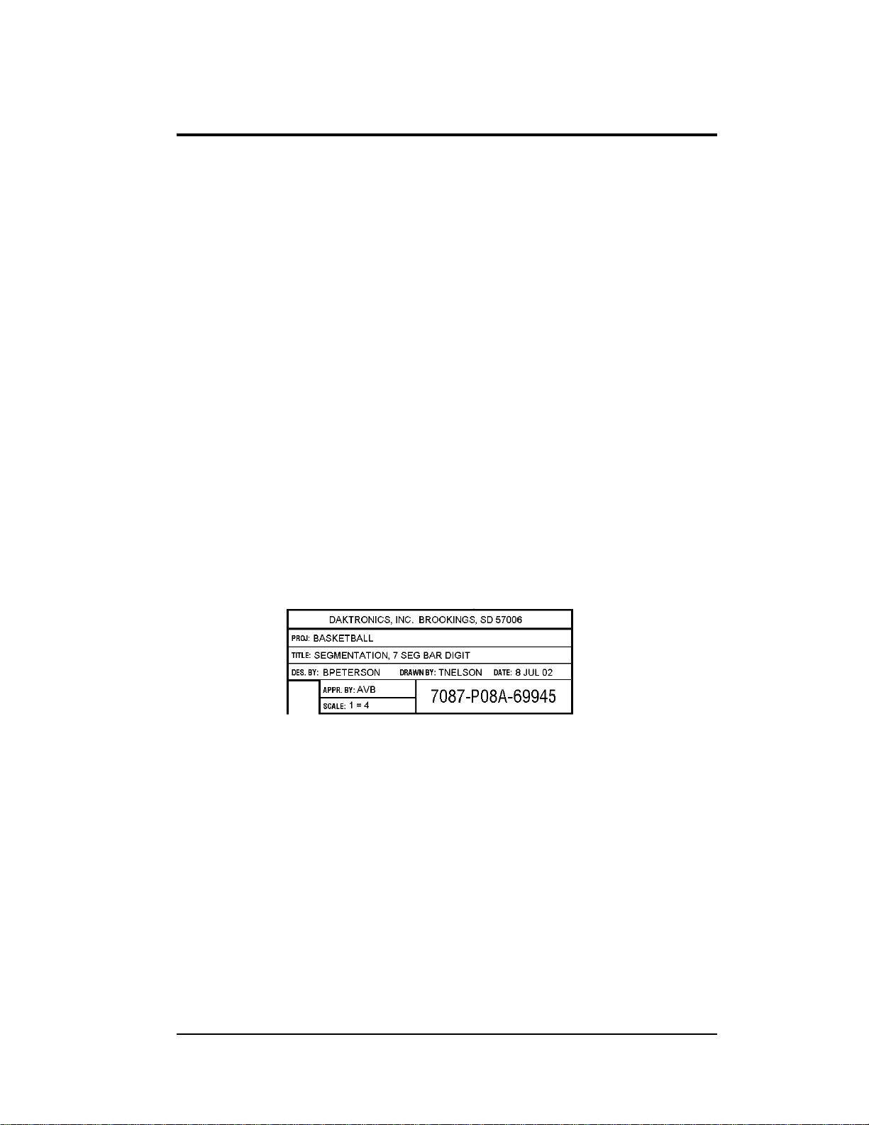
Figure 1 illustrates the Daktronics drawing numbering system. Daktronics identifies
individual engineering drawings by their drawing number (7087-P08A-69945 in the
example), which is located in the lower right corner of the drawing. This manual
refers to drawings by their last set of numbers and the letter preceding them. The
example would be Drawing A-69945.
Reference drawings in this manual are grouped and inserted in alphanumeric
order in Appendix A: Reference Drawings.
Listed below are a number of drawing types commonly used by Daktronics, along
with the information that each is likely to provide.
System Riser Diagrams: overall system layout from control room to
display, power, and phase requirements.
Shop Drawings: fan locations, transformer locations, mounting
information, power and signal entrance points, and access method (front or
rear).
Schematics: power wiring, signal wiring, panelboard or power termination
panel assignments, signal termination panel assignments, and transformer
assignments.
Introduction 1
Page 8
Final Assembly: component locations, part numbers, display dimensions,
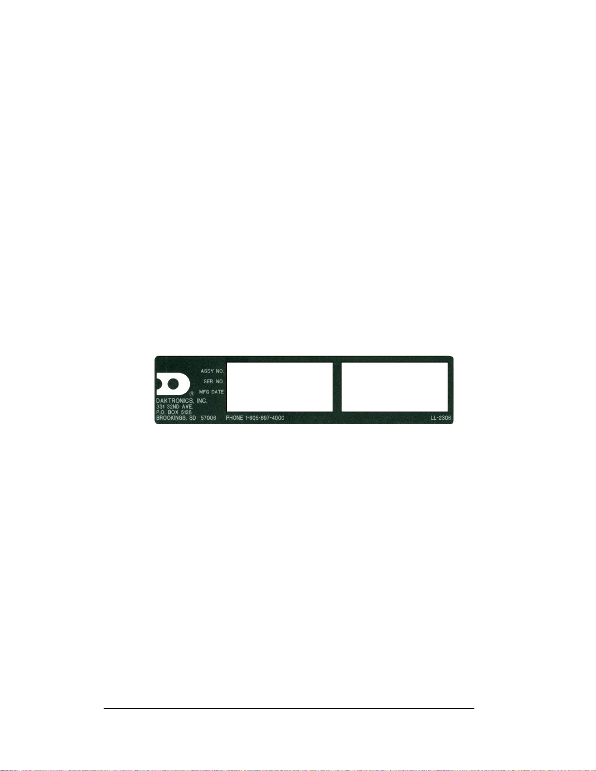
Figure 2: Scoreboard ID Label
and assembly/disassembly instructions.
All references to drawing numbers, appendices, figures, or other manuals are
presented in bold typeface, as in this example. ‘‘Refer to Drawing A-114667 for the
location of the driver enclosure.’’ Additionally, any drawings referenced within a
particular subsection are listed at the beginning of that subsection in the following
manner:
Reference Drawing:
Shop Drawing; 16 High 2 ½" Small Matrix ............ Drawing A-114667
Daktronics identifies manuals by their ED (engineering document) number, which is
located on the cover page of the manual. For example, this manual would be referred
to as ED-14091.
The serial and model numbers of a Daktronics scoreboard can be found on the ID
label on the display. The label will be similar to the one shown in Figure 2. When
calling Daktronics Customer Service, please have this information available to
ensure that your request is serviced as quickly as possible. For future reference, note
your scoreboard model number, serial number, and installation date on the front page
of this manual.
Daktronics displays are built for long life and require little maintenance. However,
from time to time, certain display components will have to be replaced. The
Replacement Parts List in Section 5 provides the names and part numbers of
components that may require replacement during the life of this display.
Following the Replacement Parts List is an explanation of Daktronics exchange and
replacement programs. Refer to these instructions if you must replace or repair any
display component.
1.2 Daktronics Nomenclature
To fully understand some Daktronics drawings, such as schematics, it is necessary to
know how various components are labeled in those drawings. You will find this
information useful when trying to communicate maintenance or troubleshooting
efforts.
2 Introduction
Page 9

The label ‘‘A’’ on a drawing item typically denotes an assembly. An assembly can
be a single circuit board or a collection of components that function together, usually
mounted on a single plate or in a single enclosure.
In addition, the following labeling formats might be found on various Daktronics
drawings:
‘‘TB _ _’’ denotes a termination block for power or signal cable.
‘‘F _ _’’ denotes a fuse.
‘‘E _ _’’ denotes a grounding point.
‘‘J _ _’’ denotes a power or signal jack.
‘‘P _ _’’ denotes a power or signal plug for the opposite jack.
Finally, Daktronics part numbers are commonly found on drawings. Those part
numbers can be used when requesting replacement parts from Daktronics Customer
Service. Take note of the following part number formats. (Not all possible formats
are listed here.)
‘‘0P- _ _ _ _- _ _ _ _’’ denotes an individual circuit board, such as a driver
board.
‘‘0A-_ _ _ _ - _ _ _ _’’ denotes an assembly, such as a circuit board and the
plate or bracket to which it is mounted. A collection of circuit boards
working as a single unit may also carry an assembly label.
‘‘W- _ _ _ _ ’’ denotes a wire or cable. Cables may also carry the assembly
numbering format in certain circumstances. This is especially true for
ribbon cables.
‘‘F- _ _ _ _ ’’ denotes a fuse.
‘‘T- _ _ _ _ ’’ denotes a transformer.
‘‘PR- _ _ _ _ _ - _’’ denotes a specially ordered part.
‘‘M- _ _ _ ’’ denotes a metal part, and ‘‘0M-_ _ _ _ _ _’’ typically denotes a
fabricated metal assembly.
1.3 Manual Overview
This manual details outdoor modular scoreboards with LED digits. It is divided into
the following sections:
Section 1 contains an overview of the product, product safety information, and
labeling and numbering descriptions.
Section 2 contains a table listing all of the mechanical specifications, circuit
specifications, and power requirements for each scoreboard module.
Section 3 contains general mechanical installation information.
Section 4 contains general electrical installation information.
Section 5 contains information needed to service the scoreboards and
troubleshoot problems.
Appendix A contains the engineering drawings referenced in this manual.
Appendix B contains drawings, descriptions, and installation instructions for
various scoreboard options.
Introduction 3
Page 10

1.4 Product Overview
Reference Drawings:
Layout View; MS-2015-11-21, G3 ............................... Drawing A-189437
Layout View; MS-2014-11-21, G3 ............................... Drawing A-189446
Layout View; MS-2018-11-21, G3 ............................... Drawing A-189492
Layout View, MS-2016-11-21, G3 ............................... Drawing A-202065
Layout View, MS-2017-11-21, G3 ............................... Drawing A-213041
Layout View, FB-2006-11-21, G3 ................................ Drawing A-221063
The scoreboards detailed in this manual are part of a family of outdoor scoring and
timing displays designed to offer simple installation and easy reliability.
Microprocessor control assures consistent operation and accuracy. The scoreboards
are illustrated in the Reference Drawings listed above.
Because this scoreboard series is based on a modular design, there can be any
number of module and caption combinations. Some displays may utilize a single
module, while others may consist of multiple modules arranged vertically.
The heavy-gauge aluminum cabinets for the displays have a 2'-4" display face and
they are 7" deep by 9'-0" long. Caption sections are also 9'-0" long, but they measure
only 7" high. Refer to Section 2 for a complete list of weights, dimensions, and
power specifications.
The four basic displays described in this manual are configured as follows:
Models MS-2014 and MS-2018 consist of two powered sections with digits
indicating clock/score and player/penalty, as well as an unpowered caption
panel. MS-2018 also features an unpowered panel that shows shots on goal.
Model MS-2015 is a single powered section with digits indicating
clock/score only.
Model MS-2016 is a three-section display with game time digits as well as
digits indicating home score, period, and guest score.
Model MS-2017 is a three-section display with game time digits as well as
digits indication home & guest score, period, foul information, player foul
information, possession and bonus..
Model FB-2006 is a three-section display with powered clock/score and
statistics sections as well as an unpowered caption panel.
Each scoreboard on this series begins with a one- or two-line section, which means
the section either has a single row or two rows of 10" numeric digits. The boards use
either red or amber LEDs (light emitting diode) to illuminate the display. LEDs are
tiny, solid-state components that use a semiconductor chip to transform electrical
current into light. They are high intensity, low energy lighting units. Because of their
LED technology, the modular scoreboards consume little power, some barely more
4 Introduction
Page 11

than a household lamp. Power usage for the stackable sections in this series ranges
from 150 W to a maximum of 450 W.
Caption sections are unpowered units that attach to the top or bottom of a digit
section. The caption sections in models MS-2014 and MS-2018 indicate PLAYER
and PENALTY for both teams and use permanent, 5" vinyl captions for the digit
mounted directly below it. The caption section in model FB-2006 indicates DOWN,
yards TO GO, BALL ON and QTR (quarter) for the digit section mounted directly
below it as well. Stackable scoreboard installations may also contain optional ad
panels, attachments which can be used to display sponsor names or other advertising
messages.
The stackable scoreboards have been designed for use with the Daktronics All
Sport 5010 Control Console. The controllers use All Sport 5000 Series sport inserts
(keyboard overlays), and the boards operate without modification on All Sport 5000
signal protocol.
Scoreboard Options
The stackable scoreboards have been designed with several standard options. Popular
add-on features include a 12 V DC horn and changeable captions. Guides for the
changeable caption panels are already installed on the MS-2014 and MS-2018
scoring and caption sections; optional panels can be customized to display team
names or for virtually any other purpose.
Each of the scoreboard options is illustrated and described in Appendix B.
1.5 Model Identification
Reference Drawings:
Layout View; MS-2015-11-21, G3................................ Drawing A-189437
Layout View; MS-2014-11-21, G3................................ Drawing A-189446
Layout View; MS-2018-11-21, G3................................ Drawing A-189492
Layout View, MS-2016-11-21, G3................................ Drawing A-202065
Layout View, MS-2017-11-21, G3................................ Drawing A-214362
Layout View, FB-2006-11-21, G3 ................................ Drawing A-221063
Daktronics scoreboards are differentiated by their model numbers: For all
scoreboards included in this manual, the two-letter prefix, MS-, identifies the model
as a multisport display. The next four numbers identify the specific model.
Most Daktronics scoreboards also carry a two-number suffix that refers to indooroutdoor status and power supply: -11 and -21 are outdoor, 120 V AC displays,
respectively. The LED scoreboards in this manual are currently configured as -11 or
-21 displays.
Reference drawings are found at the end of this manual in Appendix A: Reference
Drawings.
Introduction 5
Page 12

1.6 Product Safety Approval
Daktronics stackable scoreboards are ETL-listed and tested to CSA standards.
Contact Daktronics with any questions regarding the testing procedures.
6 Introduction
Page 13

Section 2: Specifications
The following table lists all of the mechanical and electrical specifications, as well as power
requirements for each model listed in this manual. Models are listed in alphanumeric order.
Specifications 7
Page 14

Page 15
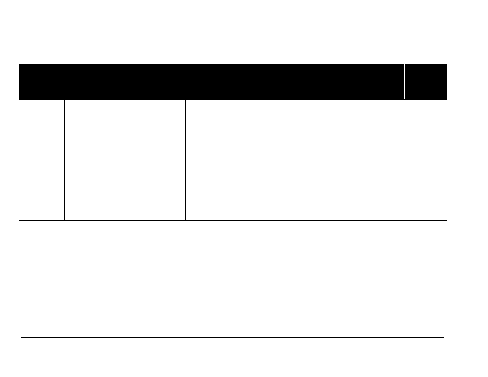
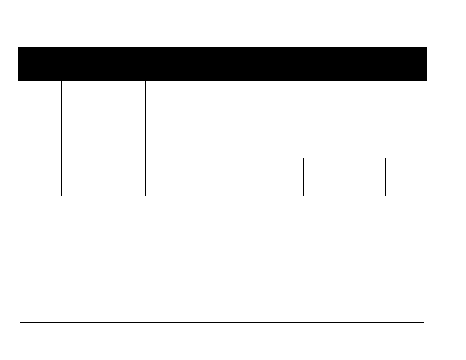
2.1 Model FB-2006-11/21
Model
Section
Dimensions
(Height, Width, Depth)
Weight
Uncrated
(Crated)
Digit Size
Digit Color
Maximum
Wattage
Power
Amps per
Line
(Single
Phase)
Driver
Number
and
Address
FB-2006
Clock/Score
H2'-4"
W9'-0"
D7"
711 mm
2743 mm
178 mm
60 lb 27 kg
(114 lb 52 kg)
10"
-11 red
-21 amber
300 W
120 V AC
2.5 A
A1 12
Captions
H7"
W9'-0"
D7"
178 mm
2743 mm
178 mm
25 lb 11 kg
(47 lb 21 kg)
None
Unpowered
Statistics
H1'-2"
W9'-0"
D7"
356 mm
2743 mm
178 mm
42 lb 19 kg
(86 lb 39 kg)
10"
-11 red
-21 amber
300 W
120 V AC
2.5 A
A1
12
Specifications 9
Page 16
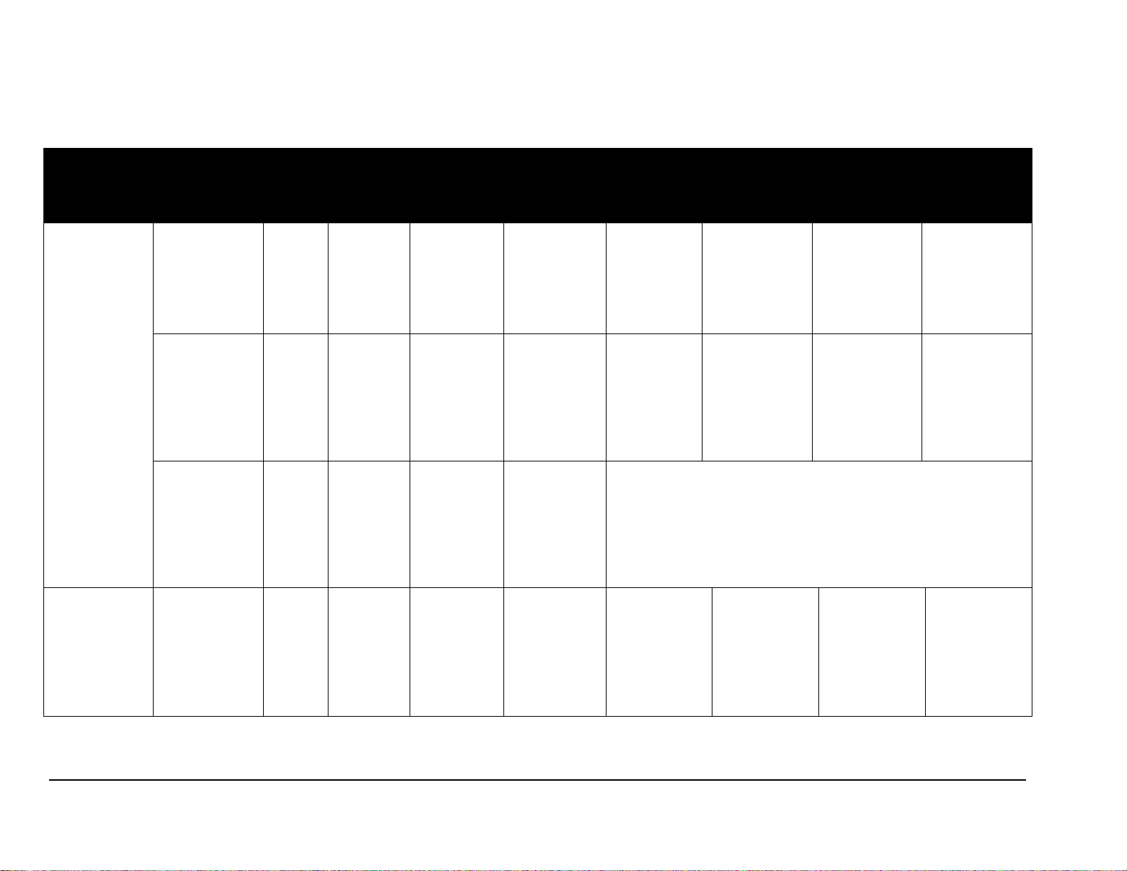
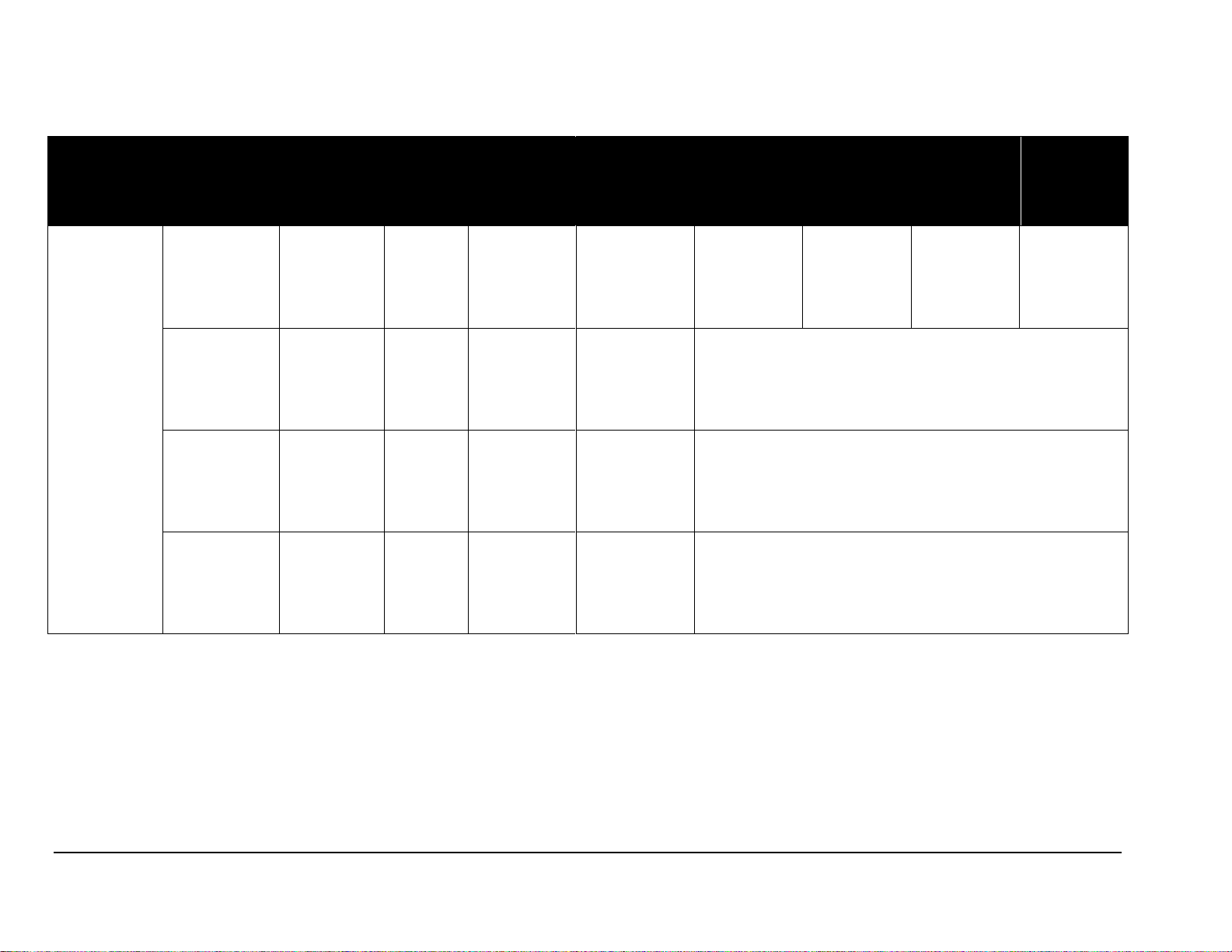
2.2 Models MS-2014 and MS-2015
Model
Section
Dimensions
(Height, Width,
Depth)
Weight
Uncrated
(Crated)
Digit Size
Digit Color
Maximum
Wattage
Power
Amps per
Line
(Single
Phase)
Driver
Number and
Address
MS-2014
Clock/Score
H2'-4"
W9'-0"
D7"
914 mm
2743 mm
177 mm
75 lb 34 kg
(142 lb 64 kg)
10"
-11 red
-21 amber
300 W
120 V AC
2.5 A
A1
71
Player/Penalty
H2'-4"
W9'-0"
D7"
914 mm
2743 mm
177 mm
85 lb 39 kg
(161 lb 73 kg)
10"
-11 red
-21 amber
600 W
120 V AC
5.0 A
A2
72
A3
73
Captions
H7"
W9'-0"
D7"
177 mm
2743 mm
177 mm
25 lb 11 kg
(47 lb 21 kg)
N/A
Unpowered
MS-2015
Clock/Score
H2'-4"
W9'-0"
D7"
914 mm
2743 mm
177 mm
60 lb 27 kg
(114 lb 51 kg)
10"
-11 red
-21 amber
300 W
300 V AC
2.5 A
A1
71
Note: Signal wires must be a minimum of 22 AWG with shield.
10 Specifications
Page 17
2.3 Model MS-2016
Model
Section
Dimensions
(Height, Width, Depth)
Weight
Uncrated
(Crated)
Digit Size
Digit Color
Maximum
Wattage
Power
Amps per
Line
(Single
Phase)
Driver
Number
and
Address
MS-2016
Clock
H1'-2"
W9'-0"
D7"
356 mm
2743 mm
177 mm
45 lb 20 kg
(86 lb 39 kg)
10"
-11 red
-21 amber
Unpowered
Captions
H7"
W9'-0"
D7"
177 mm
2743 mm
177 mm
25 lb 11 kg
(47 lb 21 kg)
None
Unpowered
Score/Period
H1'-2"
W9'-0"
D7"
356 mm
2743 mm
177 mm
45 lb 20 kg
(86 lb 39 kg)
10"
-11 red
-21 amber
300 W
120 V AC
2.5 A
A1
13
Specifications 11
Page 18
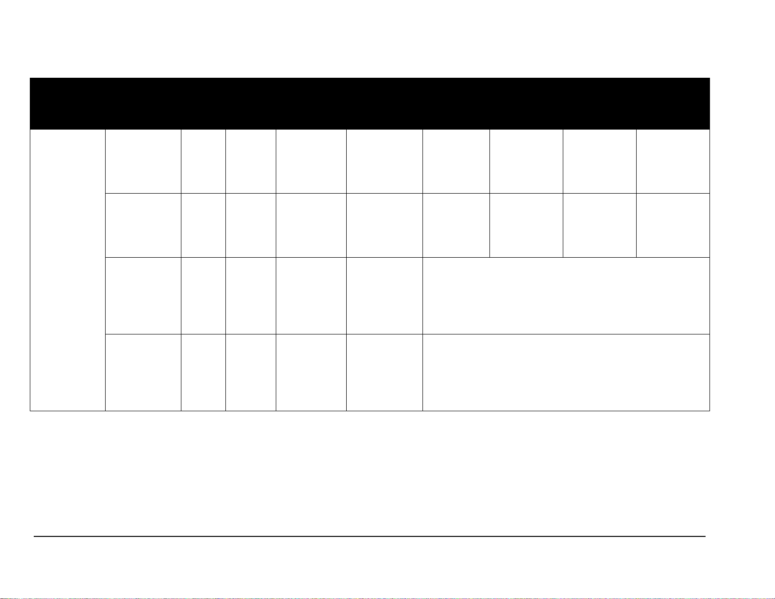
2.4 Model MS-2017
Model
Section
Dimensions
(Height, Width, Depth)
Weight
Uncrated
(Crated)
Digit Size
Digit Color
Maximum
Wattage
Power
Amps per
Line
(Single
Phase)
Driver
Number
and
Address
MS-2017
Score/Period
H1'-2"
W9'-0"
D7"
356 mm
2743 mm
177 mm
75 lb 34 kg
(142 lb 64 kg)
10"
-11 red
-21 amber
300 W
120 V AC
2.5 A
A1 17
Clock
H1'-2"
W9'-0"
D7"
356 mm
2743 mm
177 mm
75 lb 34 kg
(142 lb 64 kg)
10"
-11 red
-21 amber
Fouls/Player
Fouls
H1'-2"
W9'-0"
D7"
356 mm
2743 mm
177 mm
75 lb 34 kg
(142 lb 64 kg)
10"
-11 red
-21 amber
Captions
H7"
W9'-0"
D7"
178 mm
2743 mm
177 mm
45 lb 20 kg
(86 lb 39 kg)
10"
-11 red
-21 amber
Unpowered
12 Specifications
Page 19
2.5 Model MS-2018
Model
Section
Dimensions
(Height, Width,
Depth)
Weight
Uncrated
(Crated)
Digit Size
Digit Color
Maximum
Wattage
Power
Amps per
Line
(Single
Phase)
Driver
Number and
Address
MS-2018
Clock/Score
H2'-4"
W9'-0"
D7"
914 mm
2743 mm
177 mm
75 lb 34 kg
(142 lb 64 kg)
10"
-11 red
-21 amber
300 W
120 V AC
2.5 A
A1
71
Player/Penalty
H2'-4"
W9'-0"
D7"
914 mm
2743 mm
177 mm
85 lb 39 kg
(161 lb 161 kg)
10"
-11 red
-21 amber
600 W
120 V AC
5.0 A
A2
72
Captions
H7"
W9'-0"
D7"
177 mm
2743 mm
177 mm
25 lb 11 kg
(47 lb 21 kg)
None
Unpowered
Shots on Goal
H1'-2"
W9'-0"
D7"
356 mm
2743 mm
177 mm
45 lb 20 kg
(86 lb 39 kg)
10"
-11 red
-21 amber
Unpowered
Specifications 13
Page 20

Page 21

Section 3: Mechanical Installation
Mechanical Installation involves installing concrete footings and steel beams, attaching the
caption sections to the digit sections, and mounting the digit modules to the structure. These
steps are described in the following sections.
3.1 Installing Beams and Footings
Reference Drawings:
Beam & Footing Recommendations, MS-2014-11 ...... Drawing A-165553
Beam & Footing Recommendations, MS-2015-11 ...... Drawing A-165559
Beam & Footing Recommendations, MS-2018-11 ...... Drawing A-165561
Beam & Footing Recommendations, MS-2016-11 ...... Drawing A-175539
Beam & Footing Recommendations, MS-2017-11 ...... Drawing A-214370
Beam & Footing Recommendations, FB-2006-11/21 .. Drawing A-221087
These drawings specify the number of beams and the recommended spacing between
them. The drawings also indicate the size of beams required to support the
scoreboard at different heights under various wind speed conditions. All of the beam
specifications illustrate ‘‘W’’ shape steel beams (wide-flange I-beams). The first
number indicates the front-to-rear depth of the beam, and the second number
indicates the weight in pounds per foot of length.
Column and footing size dimensions provided with the drawings can help in
estimating installation costs. They are estimates only and are not intended for
construction purposes. Be sure that your installation complies with local building
codes and is suitable for your particular soil and wind conditions.
The columns and footings and all connection details must be designed and certified
by a professional engineer licensed to practice in the state in which scoreboard will
be installed. Daktronics does not assume any liability for any installation derived
from the information provided in this manual or for those designed and installed
by others.
3.2 Installing Captions Modules
Reference Drawing:
Caption Module Detail .................................................. Drawing A-130840
Attach the caption module to the digit module before attaching the digit module to
the beam support.
The caption modules are attached to the top or bottom of a digit module with No.10
machine screws. Refer to Drawing A-130840. With Models MS-2014-11 and MS2018-11, attach the caption module to the top of the player/penalty module. With
model FB-2006-11, attach the caption module to the top of the statistics module.
Mechanical Installation 15
Page 22

Before attaching the caption module, note its orientation. The top and bottom flanges
for holding the caption panel are different sizes. Be sure the module is oriented so
that the deeper flange, or guide, is toward the top.
The scoreboard modules are shipped with the 5" vinyl captions applied, but the
displays are also equipped with the guides needed for use with the optional custom
panels. To insert a caption panel, fit the top edge of the caption into the module's
upper guide, and then slide the bottom edge under the lower flange. Refer to
Drawing A-130840. The construction of the flanges allows the caption panels to be
lifted out for changing, rather than having to slide them out one end.
The caption panels must be properly positioned in relation to the scoreboard digits
for different activities. Refer to the scoreboard options in Appendix B for details on
changeable captions.
3.3 Mounting Digit Modules
Reference Drawings:
Beam Mounting Procedure .......................................... Drawing A-194664
Beam Mounting, Side View ......................................... Drawing A-194671
Beam Mounting, Top View .......................................... Drawing A-194674
Beam Mt., Rear, Vert. Display ..................................... Drawing A-194677
Scoreboard digit modules may be mounted directly to a wall, to universal mounting
struts (channels), or to some other support structure. Modular construction permits
varied configurations, and the unique requirements of each facility will determine the
setup and anchoring method best suited for the display. This manual addresses only
beam mounting.
Daktronics recommends using universal mounting struts, or channels. Use 3/8" bolts
through the holes in both ends of the module frame. For displays with multiple digit
modules, mount the lowest module first and work upward.
Beam Mounting Digit Modules, Outdoor
Because every display is different in terms of module configuration, scoreboard
options, and environment, every installation will be unique. Such beam-mounted
installations require that a qualified engineer provide specifications for both the
reinforced concrete footings and the steel support beams. Two beams are required for
each column of display modules, and they must be set 4'-6" apart, center-to-center.
Installations of vertical displays are shown in Drawing A-194677, which specifies
the overall space requirements for the scoreboards as well as their specific
dimensions.
Each digit module has knockouts in both the rear and the end for power and signal
entrance. Power and signal are brought into one module through these external
knockouts, and connections to other modules are made internally.
16 Mechanical Installation
Page 23

Once the support beams have been installed, the scoreboard-mounting procedure is
typically a five-step process. Refer to Drawing A-194664 for notes and illustration of the
basic procedure.
1. If you haven't already done so, attach the caption module to the top of the
player/penalty module (MS-2014-11) or to the top of the statistics module (FB2006-11.) The caption module is fastened with screws to the top of the powered
module, but it does not attach directly to the beam.
2. Begin the installation by attaching mounting brackets to the top and bottom of
the lowest digit module (the player/penalty section in the MS-2014-11 display,
the shots on goal section in the MS-2018-11 or the statistics digit section in the
FB-2006-11). Fasten the brackets to the modules by inserting 10-24 x 5/8"
screws through the holes in each bracket and threading into the captivated nuts
in the back of the module.
3. With the brackets attached, position the module against the beam and secure it
with the 15"-long threaded rods and the other washers and nuts provided. These
1/2-13 x 15" threaded rods, or mounting bolts, do not go through the beam but
pass along either side; no drilling is required. Refer to Drawings A-194671 and
A-194674. The square nuts go inside the bracket, and the hex nuts are used
inside the rear mounting angles that straddle the back of each support beam.
Tighten the assembly with a 3/4" socket, taking care not to over tighten.
4. Position the clock/score module above the caption module. Attach the mounting
brackets to the clock/score section as described in Step 2, and then secure the
module to the beams with bolts, washers, and nuts, as described in the Step 3.
5. Join the caption and clock/score modules together at the ends by inserting
screws up through the holes in the top of the lower module and into the
captivated nuts in the bottom of the upper module.
For scoreboard models other than MS-2014-11, the building process continues in the
same manner for any remaining modules. Caption modules are attached directly to
their adjoining digit modules and do not accept beam mounting brackets. Refer to
Drawing A-194671.
Mechanical Installation 17
Page 24

Page 25

Section 4: Electrical Installation
Electrical installation consists of the following process:
Providing power and ground to a disconnect near the scoreboard;
Routing power and ground from the main disconnect to the scoreboard power and
signal termination points;
Connecting the scoreboard ground to a grounding electrode at the scoreboard location;
Routing control signal cable from the control location to the scoreboard location;
Routing power and control signal cable into the initial module; and
Making connections to the adjoining modules.
These steps are described in greater detail in the following sections.
Note: Only qualified individuals should perform power routing and termination to the
display. It is the responsibility of the electrical contractor to ensure that all electrical work
meets or exceeds local and national codes.
4.1 Power
The charts in Section 2 list circuit specifications and power requirements for the
sections listed in this manual. Refer to the following sections for details of display
power installation.
Daktronics outdoor LED scoreboards have been designed for easy access to
components, and the power and control signal hookup has been simplified. Front
panels are removable to allow access to digits, cabling, and other electronic
components.
Correct power installation is imperative for proper display operation. The
subsections that follow give details of display power installation. Only qualified
individuals should attempt to complete the electrical installation; untrained personnel
should not attempt to install these displays or any of the electrical components.
Improper installation could result in serious damage to the equipment and could be
hazardous to personnel.
Grounding
Reference Drawing:
Schematic; Gen III Outdoor LED,
16 Column Drvr ............................................... Drawing A-177931
Displays MUST be grounded according to the provisions outlined in Article 250
of the National Electrical Code and according to the specifications in this manual.
Daktronics recommends a resistance-to-ground of 10 ohms or less.
The contractor performing the electrical installation can verify ground resistance.
Daktronics Sales and Service personnel can also provide this service.
Electrical Installation 19
Page 26

The display system must be connected to an earth electrode installed at the display.
Proper grounding is necessary for reliable equipment operation. It also protects the
equipment from damaging electrical disturbances and lightning. The display must be
properly grounded, or the warranty will be void. Refer to the schematic, Drawing
A-177931, for information on where to connect the grounding wire. The connection
is illustrated in the "Pwr In" detail of the Master Configuration portion of the
schematic.
The material for an earth-ground electrode differs from region to region and may
vary according to conditions present at the site. Consult the National Electrical
Code and any local electrical codes that may apply. The support structure of the
display cannot be used as an earth-ground electrode. The support is generally
embedded in concrete, and if it is in earth, the steel is usually primed or it corrodes,
making it a poor ground in either case.
Power Installation
There are two considerations for power installation: installation with ground and
neutral conductors provided, and installation with only a neutral conductor provided.
These two power installations differ slightly, as described in the following
paragraphs:
Installation with Ground and Neutral Conductors Provided
For this type of installation, the power circuit must contain an isolated earth-ground
conductor.
Under this circumstance, do not connect neutral to ground at the disconnect or at the
display. This would violate electrical codes and void the warranty. Use a disconnect
so that all hot lines and neutral can be disconnected. The National Electrical Code
requires the use of a lockable power disconnect within sight of or at the display.
Installation with Only a Neutral Conductor Provided
Installations where no grounding conductor is provided must comply with Article
250-32 of the National Electrical Code. If the installation in question meets all of the
requirements of Article 250-32, the following guidelines must be observed:
Connect the grounding electrode cable at the local disconnect, never at the
display driver/power enclosure.
Use a disconnect that opens all of the ungrounded phase conductors.
20 Electrical Installation
Page 27

4.2 Power and Signal Connection
Figure 3: Power Terminal Block
Reference Drawings:
Schematic, Gen III Outdoor LED,
16 Column Driver ................................................... Drawing A-177931
Driver; Gen III LED, 16 Col Master .............................. Drawing A-178197
Route power and signal cables into the scoreboard from the rear. There are two
knockouts for conduit connection in the back. All power and signal wiring terminates
at the driver enclosure. Drawing A-178197 illustrates the 16-column driver used in
Daktronics outdoor LED scoreboards.
To gain access to the driver enclosure, open the access door or digit panel and
remove the cover from the enclosure. Refer to the component locations drawings for
the access location for your scoreboard.
Connect power and signal cables at the appropriate locations on the driver enclosure
panel, shown in Drawings A-178197 and
A-177931.
The conventional power termination panel has been
eliminated from Daktronics outdoor scoreboards;
the power feeder circuit connects directly to a
terminal block in the driver enclosure, as shown in
Figure 3. The terminal block is located in the lower
right corner of the enclosure. Connect the power
wires as shown in the illustration. Refer to the
driver engineering drawing and the schematics
listed at the beginning of this section for additional
wiring details. The schematics include a detailed
illustration of the power termination.
Note: Driver enclosures in some earlier Daktronics scoreboards included a 120
V power receptacle. There is no 120 V receptacle in Generation III displays. If you
want power to operate the control console at the scoreboard for troubleshooting,
Daktronics recommends that you have the installation electrician provide a 120 V
outlet close to the disconnect box specifically for this purpose.
Route signal cabling to the signal surge arrestor card in the upper left corner of the
driver enclosure. The connections are labeled to permit easy installation.
Electrical Installation 21
Page 28

At the Signal In terminal block on the printed circuit board (PCB), connect the red
Figure 4: Signal Surge Arrestor Card
signal wire to the positive terminal, the black to the negative terminal, and the shield
(silver) wire to the shield terminal.
It is important that the shield wire is
properly connected to the shield
terminal on the signal surge
arrestor card. Figure 4 on the
previous page illustrates the PCB
and the terminal blocks.
For signal cable, Daktronics
recommends, as a minimum, singlepair, shielded cable, 22 AWG
(Daktronics part number W-1077).
Two-pair shielded cable
(Daktronics part W-1234) is
preferred.
Connections Between Sections
Note: The power and signal interconnect harnesses referenced in the following
section are factory-installed and in place. Only the final connection between
scoreboard modules is required for field installation. This information is presented
to document the complete installation procedure.
Models MS-2014 and MS-2018 have been configured to operate with a master/slave
driver system. Master and slave drivers function identically, but slave drivers lack
the power terminal block and signal surge arrestor card. The two drivers have been
designed to simply plug into each other via an interconnect harness, the slave
receiving redriven power and signal from the master driver. Larger scoreboards can
have as many drivers as they require.
All driver interconnect harnesses are factory installed. No additional connection is
necessary (The harness emerges from the bottom of the master driver enclosure, and
the J42 jack from the master is connected to the slave's P43 plug.). Likewise, signal
cables from drivers to digit also have been factory-installed, and no additional
connection is necessary.
For access and connection, refer to the component locations drawings and follow this
procedure:
1. Begin electrical installation by routing power and signal cables into the
scoreboard through the rear of the clock/score section. There are two
knockouts for conduit connection on the back panel. There are knockouts
on the side of the cabinet as well, if connection there is more desirable.
Both cables terminate inside the driver enclosure.
2. To access the internal components, open the PERIOD panel on the bottom
row of the section and remove the cover from the driver enclosure.
22 Electrical Installation
Page 29

3. Power terminates at the power terminal block in the driver tray. Refer to
Drawing A-177931 for wiring termination details.
4. The signal wires from the scoreboard controller connect directly to the
signal surge arrestor card, which is located on the lower left side of the
master driver on the driver tray. Refer to Drawing A-178197 for the exact
location.
There are also several power and signal interconnect cables in the slave sections of
the scoreboards that must be connected to the master driver in the clock/score
module. This involves routing the cables through the 2" holes in the cabinets during
scoreboard mounting. To complete these connections, refer to the following
instructions.
1. Open the access panels in both the top and bottom modules.
2. An 8' power and signal interconnect cable (0A-1192-1029) links the drivers
in the player/penalty module. The cable connects the J42 jack on the A2
driver assembly to the P43 plug on the A3 driver tray. The plugs and jacks
on the cable are connected to the mating connectors on the driver panel. For
field connection, simply match the numbers on the plugs with the numbers
on the jacks and insert. The connectors are all "keyed" – they can fit into the
jacks in one way only ( Note: This cable is factory-installed).
3. Next, in the player/penalty section, a 4' power and signal interconnect
harness (0A-1192-1028) is connected to the P43 plug on the A2 driver
assembly. Pull the cable up through the knockout in the top of the cabinet,
through the caption module, and into the clock/score module.
( Note: This cable is factory-installed.)
4. In the clock/score module, a second 4' harness (0A-1192-1028) is connected
to J42 on the A1 driver assembly. Pull the cable down to the 2" knockout
area, and connect the jack from this interconnect harness to the plug from
the player/penalty module, which should have been pulled up and into the
top module.
5. Replace covers and panels. If the bottom knockout in the player/penalty
module has been removed, insert a 2" hole plug in the bottom hole of the
lowest module
6. The MS-2018 has an additional shots on goal section that needs to be
connected to the master driver. Route the digit harnesses from the shots on
goal section to the player/penalty section above and plug the harness into
the driver enclosure.
Electrical Installation 23
Page 30

Page 31

Section 5: Maintenance and
Troubleshooting
IMPORTANT NOTES:
1. Disconnect power before doing any repair or maintenance
work on the scoreboard!
2. Permit only qualified service personnel to access internal
display electronics.
3. Disconnect power when not using the scoreboard.
5.1 Cabinet Specifications
Cabinets for Daktronics outdoor LED scoreboards are constructed of heavy-gauge
aluminum. Dimensions and weights for each model are listed in the chart in Section
2. Removable panels for digits and indicators and for component access are detailed
in each model's component locations drawing, listed in Section 5.2 below.
5.2 Component Location and Access
Reference Drawings:
Component Locations; MS-2015-11/-21, G3 ............... Drawing A-189417
Component Locations; MS-2014-11/-21, G3 ............... Drawing A-189532
Component Locations; MS-2018-11/-21, G3 ............... Drawing A-189535
Component Locations; MS-2016-11/-21, G3 ............... Drawing A-202250
Component Locations; MS-2017-11/-21, G3 ............... Drawing A-214362
Component Locations; FB-2006-11/-21, G3 ................ Drawing A-221085
The component locations drawings illustrate placement of all internal parts as well as
the configuration of the face panels for each of the models in this series.
For front-access scoreboards, all internal electronic components and digits can be
reached by opening a face panel, an access door, or a digit panel on the front of the
display.
To remove a digit, simply unfasten the screws and carefully lift the unit from the
board. You can then remove the harness from the connector on the back of the digit
to completely free the component.
Remove a non-digit access panel the same way: unfasten the top, side or bottom
screws holding it in place.
Maintenance and Troubleshooting 25
Page 32

Component location varies with each scoreboard model, but drivers and power and
16-Column LED Driver
Connector No.
Function
1 – 16
Output to digits and indicators
17
Power and signal input
18
Relay
19
Address
20
Protocol
signal components are typically mounted inside the scoreboard behind an access
panel or a digit.
Note: Disconnect power before servicing the display! Disconnect power, too,
when the display is not in use. Prolonged power-on may shorten the life of some
electronic components.
Replacing A Digit
Reference Drawings:
Digit Service, Stackable Scoreboards................... Drawing A-156994
Digit Assemblies; Gen III LED Digits..................... Drawing B-177679
The digit circuit board, the platform for the LEDs, is mounted to the back of the digit
panel. Refer to Drawings A-156994 and B-177679 for details. Do not attempt to
remove individual LEDs. In the case of a malfunctioning board, replace the entire
face panel.
To remove a scoreboard digit, follow these steps:
1. Open the face panel as described in the preceding section.
2. Disconnect the power/signal connector from the back of the digit. Release
the connector by squeezing together the locking tabs as you pull the
connector free.
3. The digits are secured to the inside of the panel with fixed machine screws,
spacers, and push nuts.
4. Remove the nuts and lift the digit off the standoff screws. (The push nuts
can be removed in several ways, but Daktronics recommends using a 9/32"
nut driver.)
5. Position a new digit over the screws and tighten the nuts.
6. Reconnect the power/signal connector.
Note: This is a keyed connector. It will attach in one way only.
Do not attempt to force the connection!
7. Close and secure the digit panel and test the scoreboard.
5.3 LED Drivers
26 Maintenance and Troubleshooting
In the scoreboard, the LED drivers
perform the task of switching
digits on and off. Refer to
Drawing A-178197. Each driver
has up to 19 connectors providing
power and signal inputs to the
circuit and outputs to the digits and
indicators. The connectors
function as shown in the table at
right.
Page 33

Output connectors 1 through 16 each have nine pins. Pin 7 provides power (hot) to
Figure 5: 16 Column Driver Enclosure
the digit or indicators wired to that connector. The other eight pins provide switching
connections.
For the scoreboard to receive signal and function properly, the driver must be set to
the correct address. This address is set with jumper wires in a 12-pin plug which
mates with a jack on the driver. Refer to Drawing A-115078 for a listing of the
wire/pin connections for driver addresses 1 – 128.
Replacing a Driver
Drivers are typically mounted inside the scoreboard and immediately behind a digit,
but location and mounting varies with the model of the scoreboard. Refer to the
component locations drawings at the beginning of this section for the location of
your scoreboard driver. All scoreboards in this manual are front-accessible.
Each driver is enclosed with a power supply and signal terminal block. Before a
failed driver can be reached, the enclosure must be accessed.
Follow the steps below to remove a driver.
1. Open the digit panel or scoreboard face panel as described in Section 5.2.
2. Remove the cover from the driver enclosure.
3. Disconnect all connectors from the driver. Release each connector by
squeezing together the locking tabs as you pull the connector free.
Note: When reconnecting, remember that these are keyed connectors
and will attach in one way only. Do not attempt to force the connections.
4. Remove the screws, nuts, or wing nuts securing the driver to the inside of
the enclosure. Refer to Figure 5.
5. Carefully lift the driver from the display and place it on a clean, flat surface.
Maintenance and Troubleshooting 27
Page 34

5.4 Segmentation and Digit Designation
Figure 6: Digit Designation
Reference Drawing:
Digit Service, Stackable Scoreboards ......................... Drawing A-156994
In each digit, certain LEDs always go on and off together. These groupings of LEDs
are referred to as segments. The Digit Segments A-G detail on Drawing A-156994
shows which connector pin number is wired to each digit segment, as well as the
wiring color code used throughout the display (illustrated at lower left on drawing).
The component locations drawings in
Section 5.2 specify the driver connectors
controlling the digits. Numbers
displayed in hexagons in the upper half
of each digit, as shown in Figure 6,
indicate which connector is wired to that
digit. (The lower number in the square
indicates nominal digit size.) The
drawings listed at the beginning of this
section also indicate digit designation
and specify the harnesses used for each
of the digit/driver connections.
5.5 Lightening Protection
The use of a disconnect near the scoreboard to completely cut all current-carrying
lines significantly protects the circuits against lightning damage. The National
Electrical Code also requires the disconnect. In order for this system to provide
protection, the power must be disconnected when the scoreboard is not in use. The
control console should also be disconnected from power and from the signal junction
box when the system is not in use. The same surges that may damage the
scoreboard’s driver can also damage the console’s circuit.
5.6 Troubleshooting
This section lists potential problems with the scoreboard and indicates possible
causes and corrective actions. This list does not include every possible problem, but
does represent some of the more common situations that may occur.
28 Maintenance and Troubleshooting
Page 35

Symptom/Condition
Possible Cause
Scoreboard will not light
Console not connected or poor connection
No power to control console
No power to the scoreboard
Garbled display
Internal driver logic malfunction
Control console malfunction
Digit will not light
Black wire to digit broken
Poor contact at driver connection.
Driver malfunction
Segment will not light
Broken LED or connection
Driver shift register failure
Broken wire between driver and digit
Poor contact at driver connector
Segment stays lit
Driver shift register failure
Short circuit on digit
Date appears in the wrong
place on the scoreboard
Incorrect address settings on drivers (consult
tables and set correct addresses)
5.7 Replacement Parts
Description
Part No.
LED driver, 16-col,
outdoor
0P-1192-0011
Harness, address, 12-pin
0A-1150-0064
Horn, 12 V DC, 2 A
DS-1389
Signal/surge arrestor
0P-1110-0011
Power supply, 24 V, 150 W, 86-132
V input
A-1720
Terminal block, 3-pos
TB-1059
Connector box, 2-screw type
EC-1008
Jack, power outlet, 3-pin, female
J-1021
Arrow indicators, penalty,
red LED
0P-1192-0249
(Continued on next page)
Maintenance and Troubleshooting 29
Page 36

(Continued from previous page)
Description
Part No.
Arrow indicators, penalty,
amber LED
0P-1192-0250
Digit, 10", red LED, 7-seg
0P-1192-0251
Digit, 10" ones, amber LED,
2-seg
0P-1192-0252
Digit, 10" amber LED, 2 segment
0P-1192-0288
Digit, 10" red LED, 2 segment
0P-1192-0287
Possession indicator, red LED
0P-1192-0249
Possession indicator, amber LED
0P-1192-0250
Bonus indicator, red LED
0P-1192-0289
Bonus indicator, amber LED
0P-1192-0290
Breakout board
0P-1192-0019
5.8 Daktronics Exchange and Repair and Return
Market Description
Customer
Service
Number
Schools (including community/junior colleges), religious
organizations, municipal clubs and community centers
877-605-1115
Programs
Exchange Program
The Daktronics Exchange Program is a service for quickly replacing key components
in need of repair. If a component fails, Daktronics sends a replacement part to the
customer who, in turn, returns the failed component to Daktronics. This decreases
equipment downtime. Customers who follow the program guidelines explained
below will receive this service.
Before Contacting Daktronics
Display Serial Number: ___________________________________________
Display Model Number: __________________________________________
Job/Contract Number: ___________________________________________
Date Installed: ___________________________________________________
Daktronics Customer ID Number: _________________________________
To participate in the Exchange Program, follow these steps:
1. Call Daktronics Customer Service.
30 Maintenance and Troubleshooting
Page 37

Universities and professional sporting events, live events
for auditoriums and arenas
866-343-6018
2. When the exchange part is received, mail the old part to Daktronics.
If the replacement part fixes the problem, send in the problem part being
replaced.
a. Package the old part in the same shipping materials in which the
replacement part arrived.
b. Fill out and attach the enclosed UPS shipping document.
c. Ship the part to Daktronics.
3. The defective or unused parts must be returned to Daktronics within 5
weeks of initial order shipment.
If any part is not returned within five (5) weeks, a non-refundable invoice
will be presented to the customer for the costs of replenishing the exchange
parts inventory with a new part.
Daktronics reserves the right to refuse parts that have been damaged due to
acts of nature or causes other than normal wear and tear.
Repair & Return Program
For items not subject to exchange, Daktronics offers a Repair & Return Program. To
send a part for repair, follow these steps:
1. Call or fax Daktronics Customer Service:
Refer to the appropriate market phone number in the chart on the
previous page.
Fax: 605-697-4444
2. Receive a case number before shipping.
This expedites repair of the part.
3. Package and pad the item carefully to prevent damage during
shipment.
Electronic components, such as printed circuit boards, should be
placed in an antistatic bag before boxing. Daktronics does not
recommend using packing ‘peanuts’ when shipping.
4. Enclose:
name
address
phone number
the case number
a clear description of symptoms
Maintenance and Troubleshooting 31
Page 38

Shipping Address
Daktronics Customer Service
[Case #]
201 Daktronics Drive, Dock E
Brookings, SD 57006
Daktronics Warranty and Limitation of Liability
The Daktronics Warranty and Limitation of Liability is located in Appendix C. The
Warranty is independent of Extended Service agreements and is the authority in
matters of service, repair, and display operation.
32 Maintenance and Troubleshooting
Page 39

Appendix A: Reference Drawings
Drawing Title Drawing Number
Caption Module Detail .................................................................................... A-130840
Digit Service, Stackable Scoreboards ............................................................ A-156994
Beam and Footing Recommendations, MS-2014 .......................................... A-165553
Beam and Footing Recommendations, MS-2015 .......................................... A-165559
Beam and Footing Recommendations, MS-2018 .......................................... A-165561
Beam and Footing Recommendations, MS-2016 .......................................... A-175539
Digit Assemblies; Gen III LED Digits .............................................................. B-177679
Schematic; Gen III Outdoor LED, 16 Col Drvr ................................................ A-177931
Driver; Gen III Outdoor LED, 16 Col Master ................................................... A-178197
Component Locations; MS-2015, G3 ............................................................. A-189417
Layout View; MS-2015, G3 ............................................................................. A-189437
Layout View; MS-2014, G3 ............................................................................. A-189446
Layout View; MS-2018, G3 ............................................................................. A-189492
Component Locations; MS-2014, G3 ............................................................. A-189532
Component Locations; MS-2018, G3 ............................................................. A-189535
Beam Mounting, Procedure ............................................................................ A-194664
Beam Mounting Side View ............................................................................. A-194671
Beam Mounting, Top View ............................................................................. A-194674
Beam Mounting, Rear View, Vertical Display ................................................. A-194677
Layout View; MS-2016-11, G3 ....................................................................... A-202065
Component Locations; MS-2016-11/-21, G3 .................................................. A-202250
Layout View; MS-2017-11, G3 ....................................................................... A-213041
Component Locations; MS-2017-11/-21, G3 .................................................. A-214362
Beam and Footing Recommendations, MS-2017 .......................................... A-214370
Layout View; FB-2006-11, G3 ........................................................................ A-221063
Component Locations; FB-2006-11/-21, G3 .................................................. A-221085
Beam and Footing Recommendations, FB-2006-11/-21 ................................ A-221087
Reference Drawings 33
Page 40

Page 41

Page 42

Page 43

Page 44

Page 45

Page 46

Page 47

Page 48

Page 49

Page 50

Page 51

Page 52

Page 53

Page 54

Page 55

Page 56

Page 57

Page 58

Page 59

Page 60

Page 61

Page 62

Page 63

Page 64

Page 65

Page 66

Page 67

Page 68

Page 69

Appendix B: Scoreboard Options
Drawing Title Drawing Number
Horn, 12 V DC w/Filter .................................................................................... B-111265
Caption Module Detail .................................................................................... A-130840
Scoreboard Options 35
Page 70

Page 71

Page 72

Page 73

Appendix C: Daktronics Warranty and
Limitation of Liability
Appendix C 37
Page 74

Page 75

Copyright © Daktronics, Inc. SL-02374 Rev 10 02-Mar-2009 Page 1 of 2
DAKTRONICS
WARRANTY AND LIMITATION OF LIABILITY
This Warranty and Limitation of Liability (the “Warranty”) sets forth the warranty provided by Daktronics with respect to the Equipment. By
accepting delivery of the Equipment, Purchaser agrees to be bound by and accept these terms and conditions. All defined terms within
the Warranty shall have the same meaning and definition as provided elsewhere in the Agreement.
DAKTRONICS WILL ONLY BE OBLIGATED TO HONOR THE WARRANTY SET FORTH IN THESE TERMS AND CONDITIONS UPON RECEIPT OF FULL
PAYMENT FOR THE EQUIPMENT.
1. Warranty Coverage
2. Exclusion from Warranty Coverage
A. Daktronics warrants to the original end-user that the Equipment will be free from Defects (as defined below) in materials and
workmanship for a period of one (1) year (the “Warranty Period”). The warranty period shall commence on the earlier of: (i) four
weeks from the date that the equipment leaves Daktronics’ facility; or (ii) Substantial Completion as defined herein. The warranty
period shall expire on the first anniversary of the commencement date.
“Substantial Completion” means the operational availability of the Equipment to the Purchaser in accordance with the
Equipment’s specifications, without regard to punch-list items, or other non-substantial items which do not affect the operation of
the Equipment.
B. Daktronics’ obligation under this Warranty is limited to, at Daktronics’ option, replacing or repairing, any Equipment or part
thereof that is found by Daktronics not to conform to the Equipment’s specifications. Unless otherwise directed by Daktronics,
any defective part or component shall be returned to Daktronics for repair or replacement. Daktronics may, at its option,
provide on-site warranty service. Daktronics shall have a reasonable period of time to make such replacements or repairs and
all labor associated therewith shall be performed during regular working hours. Regular working hours are Monday through
Friday between 8:00 a.m. and 5:00 p.m. at the location where labor is performed, excluding any holidays observed by either
Purchaser or Daktronics.
C. Daktronics shall pay ground transportation charges for the return of any defective component of the Equipment. If returned
Equipment is repaired or replaced under the terms of this warranty, Daktronics will prepay ground transportation charges back to
Purchaser; otherwise, Purchaser shall pay transportation charges to return the Equipment back to the Purchaser. All returns must
be pre-approved by Daktronics before shipment. Daktronics shall not be obligated to pay freight for any unapproved return.
Purchaser shall pay any upgraded or expedited transportation charges.
D. Any replacement parts or Equipment will be new or serviceably used, comparable in function and performance to the
original part or Equipment, and warranted for the remainder of the Warranty Period. Purchasing additional parts or Equipment
from the Seller does not extend this Warranty Period.
E. Defects shall be defined as follows. With regard to the Equipment (excepting LEDs), a “Defect” shall refer to a material
variance from the design specifications that prohibit the Equipment from operating for its intended use. With respect to LEDs,
“Defects” are defined as LED pixels that cease to emit light. The limited warranty provided by Daktronics does not impose any
duty or liability upon Daktronics for partial LED pixel degradation. Nor does the limited warranty provide for the replacement or
installation of communication methods including but not limited to, wire, fiber optic cable, conduit, trenching, or for the purpose
of overcoming local site interference radio equipment substitutions.
THIS LIMITED WARRANTY IS THE ONLY WARRANTY APPLICABLE TO THE EQUIPMENT AND REPLACES ALL OTHER WARRANTIES OR
CONDITIONS, EXPRESS OR IMPLIED, INCLUDING, BUT NOT LIMITED TO, THE IMPLIED WARRANTIES OR CONDITIONS OF
MERCHANTABILITY AND FITNESS FOR A PARTICULAR PURPOSE. SPECIFICALLY, EXCEPT AS PROVIDED HEREIN, THE SELLER
UNDERTAKES NO RESPONSIBILITY FOR THE QUALITY OF THE EQUIPMENT OR THAT THE EQUIPMENT WILL BE FIT FOR ANY PARTICULAR
PURPOSE FOR WHICH PURCHASER MAY BE BUYING THE EQUIPMENT. ANY IMPLIED WARRANTY IS LIMITED IN DURATION TO THE
WARRANTY PERIOD. NO ORAL OR WRITTEN INFORMATION, OR ADVICE GIVEN BY THE COMPANY, ITS AGENTS OR EMPLOYEES,
SHALL CREATE A WARRANTY OR IN ANY WAY INCREASE THE SCOPE OF THIS LIMITED WARRANTY.
THIS LIMITED WARRANTY IS NOT TRANSFERABLE.
The limited warranty provided by Daktronics does not impose any duty or liability upon Daktronics for:
A Any damage occurring, at any time, during shipment of Equipment unless otherwise provided for in the Agreement. When
returning Equipment to Daktronics for repair or replacement, Purchaser assumes all risk of loss or damage, and agrees to use
any shipping containers that might be provided by Daktronics and to ship the Equipment in the manner prescribed by
Daktronics;
B. Any damage caused by the unauthorized adjustment, repair or service of the Equipment by anyone other than personnel of
Daktronics or its authorized repair agents;
Page 76

Copyright © Daktronics, Inc. SL-02374 Rev 10 02-Mar-2009 Page 2 of 2
C. Damage caused by the failure to provide a continuously suitable environment, including, but not limited to: (i) neglect or
misuse, (ii) a failure or sudden surge of electrical power, (iii) improper air conditioning or humidity control, or (iv) any other cause
other than ordinary use;
D. Damage caused by fire, flood, earthquake, water, wind, lightning or other natural disaster, strike, inability to obtain materials
or utilities, war, terrorism, civil disturbance or any other cause beyond Daktronics’ reasonable control;
E. Failure to adjust, repair or replace any item of Equipment if it would be impractical for Daktronics personnel to do so because
of connection of the Equipment by mechanical or electrical means to another device not supplied by Daktronics, or the
existence of general environmental conditions at the site that pose a danger to Daktronics personnel;
F. Any statements made about the product by salesmen, dealers, distributors or agents, unless such statements are in a written
document signed by an officer of Daktronics. Such statements as are not included in a signed writing do not constitute
warranties, shall not be relied upon by Purchaser and are not part of the contract of sale;
G. Any damage arising from the use of Daktronics products in any application other than the commercial and industrial
applications for which they are intended, unless, upon request, such use is specifically approved in writing by Daktronics; or
H. Any performance of preventive maintenance.
3. Limitation of Liability
4. Assignment of Rights
5. Dispute Resolution
6. Governing Law
7. Availability of Extended Service Agreement
Daktronics shall be under no obligation to furnish continued service under this Warranty if alterations are made to the Equipment
without the prior written approval of Daktronics.
It is specifically agreed that the price of the Equipment is based upon the following limitation of liability. In no event shall
Daktronics (including its subsidiaries, affiliates, officers, directors, employees, or agents) be liable for any special, consequential,
incidental or exemplary damages arising out of or in any way connected with the Equipment or otherwise, including but not
limited to damages for lost profits, cost of substitute or replacement equipment, down time, lost data, injury to property or any
damages or sums paid by Purchaser to third parties, even if Daktronics has been advised of the possibility of such damages. The
foregoing limitation of liability shall apply whether any claim is based upon principles of contract, tort or statutory duty, principles
of indemnity or contribution, or otherwise.
In no event shall Daktronics be liable to Purchaser or any other party for loss, damage, or injury of any kind or nature arising out of
or in connection with this Warranty in excess of the purchase price of the Equipment actually delivered to and paid for by the
Purchaser. The Purchaser’s remedy in any dispute under this Warranty shall be ultimately limited to the Purchase Price of the
Equipment to the extent the Purchase Price has been paid.
The Warranty contained herein extends only to the original end-user (which may be the Purchaser) of the Equipment and no
attempt to extend the Warranty to any subsequent user-transferee of the Equipment shall be valid or enforceable without the
express written consent of Daktronics.
Any dispute between the parties will be resolved exclusively and finally by arbitration administered by the American Arbitration
Association (“AAA”) and conducted under its rules, except as otherwise provided below. The arbitration will be conducted
before a single arbitrator. The arbitration shall be held in Brookings, South Dakota. Any decision rendered in such arbitration
proceedings will be final and binding on each of the parties, and judgment may be entered thereon in any court of competent
jurisdiction. This arbitration agreement is made pursuant to a transaction involving interstate commerce, and shall be governed
by the Federal Arbitration Act.
The rights and obligations of the parties under this warranty shall not be governed by the provisions of the United Nations
Convention on Contracts for the International Sales of Goods of 1980. Both parties consent to the application of the laws of the
State of South Dakota to govern, interpret, and enforce all of Purchaser and Daktronics rights, duties, and obligations arising
from, or relating in any manner to, the subject matter of this Warranty, without regard to conflict of law principles.
For Purchaser’s protection, in addition to that afforded by the warranties set forth herein, Purchaser may purchase extended
warranty services to cover the Equipment. The Extended Service Agreement, available from Daktronics, provides for electronic
parts repair and/or on-site labor for an extended period from the date of expiration of this warranty. Alternatively, an Extended
Service Agreement may be purchased in conjunction with this warranty for extended additional services. For further information,
contact Daktronics Customer Service at 1-800-DAKTRONics (1-800-325-8766).
 Loading...