

Page 1
Ethernet Switch Enclosure Installation Quick Guide
Applications
When two primary displays are installed within 25 feet of each other, use the Ethernet switch enclosure to
eliminate the need for a second communications kit.
Mounting
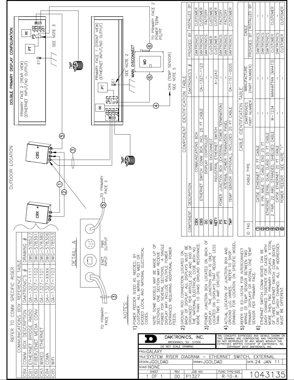
The Ethernet switch enclosure must be within 25 feet of the communication box. If using more than two
primary displays, the Ethernet switch enclosure can be daisy chained to a total of three Ethernet switch
enclosures. All display IP addresses must be different. Refer to attached drawing, DWG-1043135, for
additional information
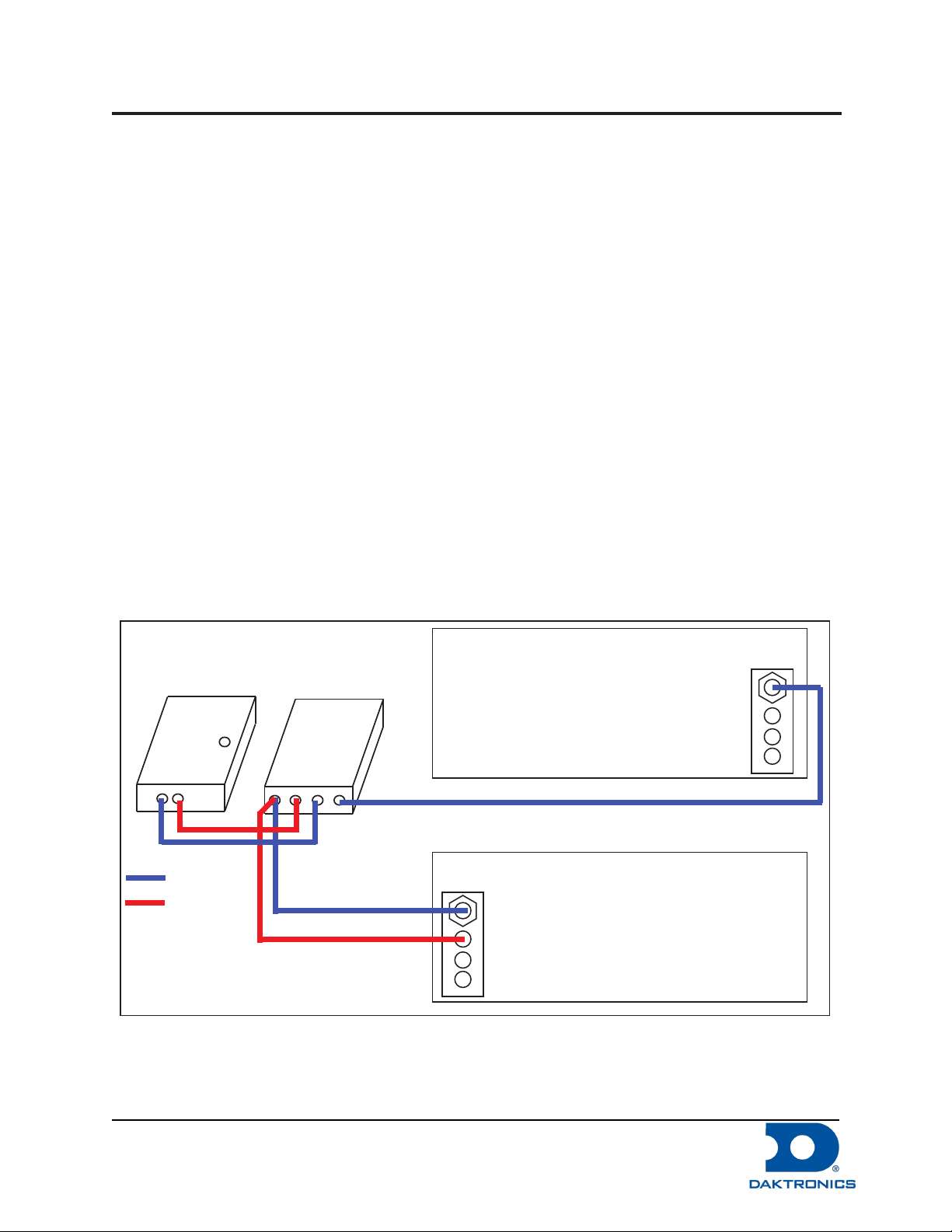
1. Mount the Ethernet switch enclosure between the displays and ensure the cables exit the bottom
of the enclosure.
2. Connect the Ethernet quick connect cable from the communications enclosure to J10 on the
Ethernet switch enclosure.
3. Connect the 6-pin quick connect cable from the communications enclosure to J9 on the Ethernet
switch enclosure.
4. Route the Ethernet and 6-pin quick connect from the Ethernet switch enclosure to J32 and J33
jacks on one of the displays.
5. Connect the Ethernet cable from the Ethernet switch enclosure to J32 on the back of the display.
6. Connect the 6-pin to J33 on the back of the display.
7. Connect the Ethernet quick connect cable from the Ethernet switch enclosure to J32 on the second
display.
Primary 2 - Rear View
Comm. Box
Ethernet
6-Pin Power
Ethernet Switch
J10
J9
Must be Less
Than 25 Feet
Must be Less Than 25 Feet
Primary 1 - Front View
J32
J33
Figure 1: Power and Signal Routing from the Ethernet Switch to the Displays
J32
DD1946340 Rev 1
13 December 2012
PO Box 5128 201 Daktronics Drive, Brookings, SD 57006-5128
tel: 800-325-8766 fax: 605-697-4700
www.daktronics.com
Page 2
 Loading...