

Page 1
Quick Guide: Ethernet Switch Installation
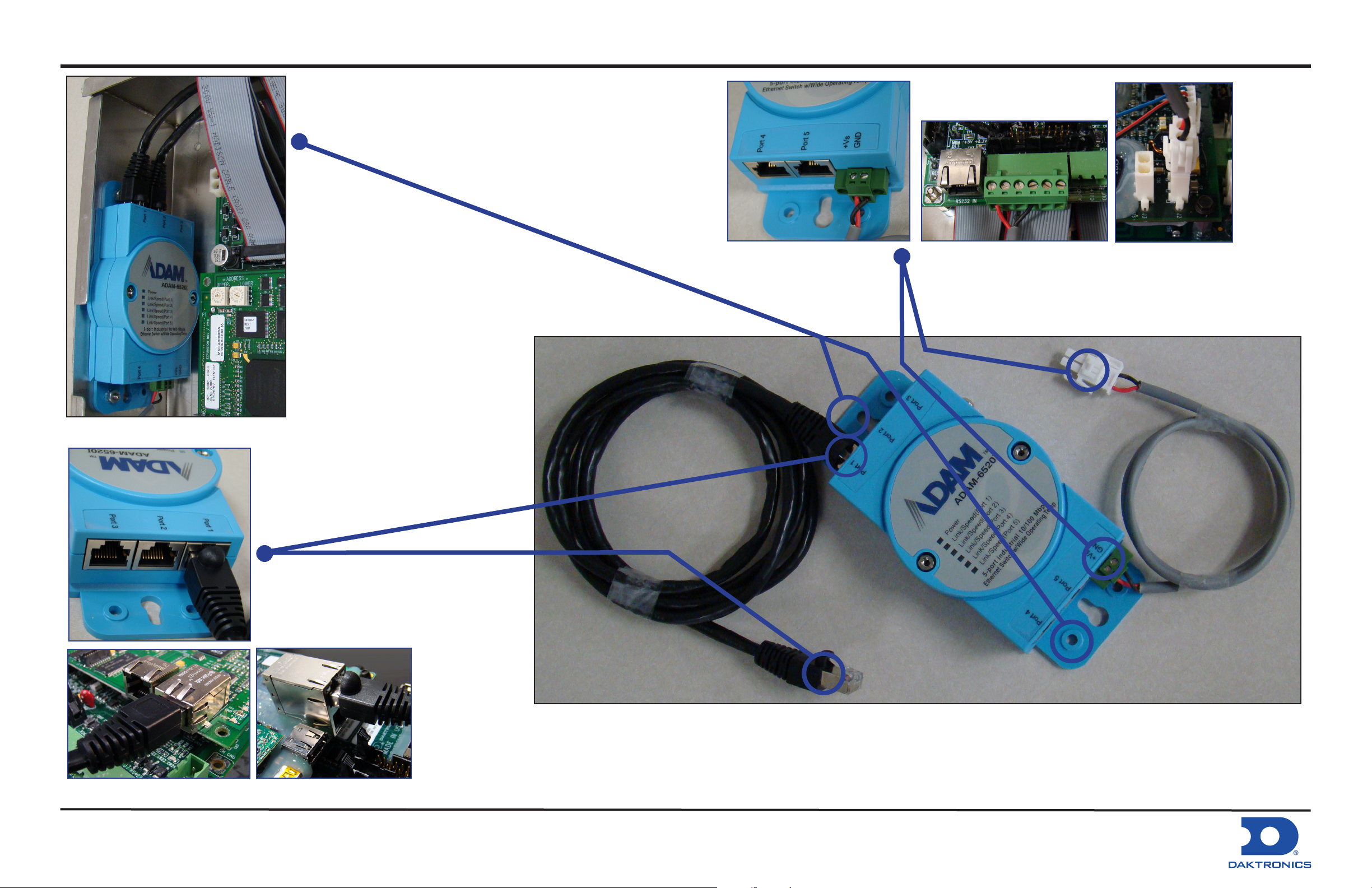
1. Attach switch to standoff
pair on left side of controller
enclosure.
3a. External Signal Enclosure: Connect
incoming Ethernet signal cable to open
switch port. Route Ethernet cable from open
switch port to Ethernet input on controller -
2a. Galaxy Display: Re-
move power plug and connect
RED wire to Pin 1 of TB1 and
BLACK wire to Pin 4.
2b. GalaxyPro Revolution
Display: Insert power plug into
J2 jack on controller.
Galaxy Display: J4 GalaxyPro Revolution Display: J7
DD1442218 Rev 0
18 September 2008
3b. Internal Signal Termination: Route
Ethernet cable from communication device
to open switch port. Route Ethernet cable
from open switch port to Ethernet input on
controller - Galaxy Display: J4 - GalaxyPro
Revolution Display: J7.
P.O. Box 5128 201 Daktronics Dr. Brookings, SD 57006-5128
tel: 605-692-0200 ext. 56219 or 888-325-7446 fax: 605-692-0381
www.daktronics.com email: Support@daktronics.com
4. Route Ethernet cable(s) from open
switch port(s) through conduit to other
display(s).
 Loading...