

Page 1

900 MHz (0A-1327-1111)
and 2.4GHz (A-3446)
Ethernet Bridge Radio (EBR)
Pair Manual
DD1685027 Rev 08—8 May 2014
201 Daktronics Drive PO Box 5128 Brookings, SD 57006
tel 800-843-5843 fax 605-697-4700
Table of Contents 1
www.daktronics.com
Page 2

DD1685027
P1327
Rev 08—8 May 2014
DAKTRONICS, INC.
Copyright © 2009-2014
All rights reserved. While every precaution has been taken in the preparation of this manual, the publisher assumes no
responsibility for errors or omissions. No part of this book covered by the copyrights hereon may be reproduced or copied in any
form or by any means—graphic, electronic, or mechanical, including photocopying, taping, or information storage and retrieval
systems—without written permission of the publisher.
Daktronics is a registered trademark of Daktronics, Inc.
All other trademarks are the property of their respective companies.
Page 3

Table of Contents
Section 1: Introduction .......................................................................................................................................... 1
1.1 Component Identification ................................................................................................................................... 1
Section 2: Installation ........................................................................................................................................... 3
2.1 System/Cable Requirements .............................................................................................................................. 3
Section 3: Maintenance ......................................................................................................................................... 5
3.1 LED Diagnostics ................................................................................................................................................... 5
3.2 Replacement Parts List ....................................................................................................................................... 6
Section 4: Troubleshooting and Radio Diagnostics ........................................................................................... 7
4.1 Download the Utility ........................................................................................................................................... 7
4.2 Open the Utility .................................................................................................................................................... 7
4.3 Network Map ........................................................................................................................................................ 7
Section 5: Technical Specications .................................................................................................................... 9
5.1 900xTR (900 MHz)Technical Specifications ...................................................................................................... 9
5.2 2400xTR (2.4 GHz) Technical Specifications .................................................................................................. 10
5.3 FCC Compliance ................................................................................................................................................. 10
Warning (Part 15.21) ................................................................................................................................... 10
RF Exposure (OET Bulletin 65) ................................................................................................................. 10
Information to the User - Part 15.105 (b) ................................................................................................. 10
Table of Contents i
Page 4

Page 5
Section 1: Introduction
1.1 Component Identication
Ethernet: A technology for high-speed bandwidth connectivity over local area networks (LAN).
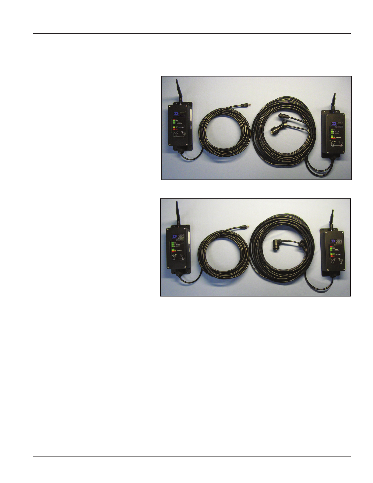
Client Radio: This radio receives
signal from the server radio. The
client radio is connected to and
receives power from the display.
Signal between the client and the
display is both transmitted and
received.
Server Radio: This radio is connected
to the local Ethernet network through
a DC injector which provides power
to the radio. It transmits and receives
information to and from the client
radio at the display.
DC Injector: This unit, shown in
Figure 5, receives signal in from the
customer’s network and relays signal
out to the radio. It contains a power
input to power the server radio.
Figure 1: Ethernet Bridge Radios – Two-Wire Client Radio
Note: The DC Injector is for indoor
use only.
Optional USB to Ethernet Adapter:
This bypasses complex network
configuration in situations where
simple point-to-point communication
is required. The adapter creates
a secondary network, which is
dedicated for communication with a
Daktronics Galaxy® display. Normal network operation is still enabled through the primary network.
Figure 2: Ethernet Bridge Radios – Single-Wire (10-pin Quick Connect) Client
Radio
Introduction 1
Page 6

Page 7

Section 2: Installation
The controller has either a default IP address (172.16.192.25) for Galaxy® displays or a DHCP address for GalaxyPro®
Series displays. Once the default IP address is used to connect to the display, it can be changed to a personalized
address. Refer to the display manual for further information on setting an IP address. Various LAN and Internet
service providers (ISP) have differing IP requirements. Consult the network administrator or ISP for more
information. The DHCP address automatically adjusts to suit the local network.
2.1 System/Cable Requirements
In an Ethernet radio system, two radios are required. A server radio transmits/receives signal to/from a
client radio, shown in Figure 1 and Figure 2, at the display. The server radio connects to the Ethernet LAN
through a DC injector.
Daktronics provides a yellow 20-foot CAT 5e Ethernet cable, which is required to connect the DC injector to
the LAN. The customer must supply a longer cable if it is needed.
Ethernet and power cables are provided to connect the client radio to the display and the server radio to the
DC injector.
A Windows®-based computer is required (but not provided) to run Venus® 1500 control software.
An Ethernet radio-controlled display requires the following connections, refer to Figure 3 for a system layout:
1,500 Feet Maximum
20 Feet Minimum
▲
▲
▲
▲
Recommend
20 Feet
Minimum
▲
Client
Radio
PRIMARY DISPLAY - REAR
PRIMARY
Network Connections
Inside Building
120V AC
Computer
Running
Venus 1500
Network Switch
Optional USB to Ethernet Adapter
Cat-5E 300 ft. max from network switch to radio
Injector of Power over Ethernet
Switch
Hub
▲
- 4- to 26-Foot Radio Transmission Zone Depending on
Distance (900 MHz Radios)
- 1.5- to 13-Foot Radio Transmission Zone
Server
Radio
AC
Input
Data+VDC
▪▪▪▪▪
RJ45
output
Data
▪▪▪▪▪
Input
Power
Injector
Splitter
Recommend
20 Feet
Minimum
(2.4 GHz Radios)
- Avoid Obstructions Within This Zone
▲
▲
Figure 3: Wireless Ethernet Display Layout
Installation 3
Page 8

Daktronics recommends radios be mounted with antennas
Antenna Alignment Guidelines
Right
Wrong
Wrong
pointing upward. Figure 4 illustrates correct and incorrect
antenna placement.
Do not mount the radios with the wire grommet pointing
upward.
There are two types of client radio connectors for Galaxy products
– two wire – Figure 1 and single wire – Figure 2.
1. A CAT 5e Ethernet cable is routed from the LAN switch/
router to the DC injector.
Note: The DC Injector is for indoor use only.
2. The Ethernet cable connects to the Switch Hub jack on
the DC injector, as shown in Figure 5.
3. The DC injector is provided with an AC power adapter.
The AC power adapter is connected to the AC input
jack on the DC Injector and inserted into a 120 VAC
wall outlet.
4. The server radio is provided with a 25 ft.
(7.6 m) attached Ethernet cable. This
Ethernet cable is connected to the RJ45 jack
on the DC injector.
The maximum distance between the
Figure 6: Extend Cat 5e Cable Using a Cat 5e Inline Coupler
network switch and server radio is 300 ft.
(91.44 m).
Note: Install a Cat 5e inline coupler, example shown
in Figure 6, to the end of the server radio cable and
connect it to a high-quality Cat 5e cable.
Figure 4: Antenna Alignment Examples
Figure 5: DC Injector
5. Mount the server radio outdoors for best signal
quality. Indoor mounting significantly reduces
signal quality and can cause communication issues
to the display.
6. Mount the client radio within 25 ft. (7.6 m) of the
input jacks.
7. Route the signal quick-connect cables from the
enclosure to the rear of the display.
The cable from the enclosure to the display can be
routed through conduit or through the display pole,
and should be secured to protect it from weather or
vandalism. Provide drip loops to prevent water
migration to display quick-connect interface board.
8. Connect the quick-connect cables to the top two (J32
and J33) jacks. Refer to Figure 7 and Figure 8 for
examples. Or connect the quick-connect cable to the
middle jack if the display is a single-cable design, as
shown in Figure 9 and Figure 10.
Figure 7: Quick-Connect
Cables - Two-Wire Design
Figure 8: Input Jacks
Figure 9: Input Jacks
Figure 10: 10-Pin Quick-
Connect Cable - SingleWire Design
4 Installation
Page 9

Section 3: Maintenance
3.1 LED Diagnostics
Use the label affixed to the radio, shown in Figure 11 and Figure 19, and the
16 diagnostic LEDs on boards inside the housing of both the server and client
radios to determine whether the radio is linking properly and which channel is
currently being used.
The following chart also describes the diagnostic LEDs’ functions:
Name Function Color
Power Unit has power and has successfully booted. Red
RF TX Radio transmission is occurring. Green
RF RX Radio reception is occurring. Green
Ethernet Link The Ethernet Port has a valid Ethernet connection. Green
CH 1
CH 2
CH 4
CH 8
CH 16 (not used with
900 MHz radios)
CH 32 (not used)
By adding the numbers that are lit, the user can
determine the current radio channel.
900MHz Radios
903.12500 MHz
1
905.20833 MHz
2
907.29167 MHz
3
909.37500 MHz
4
911.45833 MHz
5
913.54167 MHz
6
915.62500 MHz
7
917.70833 MHz
8
919.79167 MHz
9
921.87500 MHz
10
923.95833 MHz
11
926.04167 MHz
12
Green
Minimum Distance - 20 ft
Maximum Distance - 1500 ft
Minimum Height - 20 ft
Mount in Direct Line of Sight
Mount Both Radios Outdoors
Mount radios with antennas vertical and
provide free and clear radiation pattern
Power
RF Receive
RF Transmit
Ethernet Link
Channel
Sum values to
determine channel
32 16 8 4 2 1
BEST
FAIR
Link Quality
POOR
Figure 11: Radio Label
Link Quality Meter:
The more LEDs that
are lit, the higher the
link quality
2.4 GHz Radios
Auto Mode
0
2.416667 GHz
1
2.418750 GHz
2
2.420833 GHz
3
2.422917 GHz
4
2.425000 GHz
5
2.427083 GHz
6
2.429167 GHz
7
2.431250 GHz
8
2.433333 GHz
9
2.435417 GHz
10
2.437500 GHz
11
2.439583 GHz
12
2.441667 GHz
13
2.443750 GHz 29 2.475000 GHz
14
Excellent link quality No retransmissions Green
Very good link quality Few retransmissions Green
Good link quality Occasional retransmissions Amber
Fair link quality Some retransmissions Amber
Poor link quality Many retransmissions Red
No link quality No link available Red
15
16
17
18
19
20
21
22
23
24
25
26
27
28
2.445833 GHz
2.447917 GHz
2.450000 GHz
2.452083 GHz
2.454167 GHz
2.456250 GHz
2.458333 GHz
2.460417 GHz
2.462500 GHz
2.464583 GHz
2.466667 GHz
2.468750 GHz
2.470833 GHz
2.472917 GHz
Maintenance 5
Page 10

3.2 Replacement Parts List
The following table contains some of the items that may need to be replaced
over a period of time.
0P-1127-0024
If a component is not listed in the replacement parts list, use the label to order
a replacement. Most components within this display carry a label that lists the
part number of the unit. A typical label is shown in Figure 12 with the part
number in bold.
900 xTR Radios (900 MHz)
Part Description Part Number
DC Injector with Internal Transformer
and Power Cable
Patch Cable, Ethernet RJ45 2ft. W-1537
900 MHz Ethernet Bridge Radio Kit With
6-Pin Quick Connect (2 Wire Client)
902-928 MHz Antenna A-2545
A-2551
0A-1327-1111
2400 xTR Radios (2.4 GHz)
Part Description Part Number
DC Injector with Internal Transformer
and Power Cable
Patch Cable, Ethernet RJ45 2ft. W-1537
2.4 GHz Ethernet Bridge Radio Kit With
6-Pin Quick Connect (2-Wire Client)
2.4 GHz Antenna A-3457
SN: 2465
02/19/12 Rev. 1
Figure 12: Typical Parts Label
A-2551
A-3446
6 Maintenance
Page 11

Section 4: Troubleshooting and Radio Diagnostics
Server Client
Control
Computer Display
Status LEDs
Signal
Strength
Ethernet Connection Information
The Daktronics Ethernet Bridge Radio Diagnostics utility helps determine if radios are linked and communicating
effectively.
Note: The utility can only be used on Ethernet Bridge Radios with Radio Firmware version v81 or greater and Web
Page Firmware version v1.58.4250 or greater.
4.1 Download the Utility
Go to http://dakles.daktronics.com/downloads/venus1500/utils/
EBRDiagnostics.
Click EBRDiagSetup.exe and Save. Save the file on your computer’s hard
drive. Run the installer from that location to complete the installation
process.
4.2 Open the Utility
Access the utility by clicking the Windows Start button located at the
bottom left of your computer screen. Click All Programs > Daktronics >
Utilities > Ethernet Bridge Radio Diagnostics, refer to Figure 13.
4.3 Network Map
The Network Map opens when you start the utility. It provides basic
connection and signal strength information.
Information shown in the Network Map reloads
every 6 seconds by default. Each time data updates,
Reloading... appears on the map, as shown in
Figure 14.
A green line with
connection information, for example 100
Mbps, shown below it reflects a successful
Ethernet Connection between the Control
Computer, Server and Client Radios, and
Display. A green line will also link the
server and client radios, as shown in
Figure 15.
When a red line with either Disconnected
or Unknown below it appears in the
Network Map, you will know the Ethernet
Connection is not successful.
Figure 13: Open the Ethernet Bridge
Radio Diagnostics Utility
Figure 14: Data Update
Figure 15: Daktronics Ethernet Bridge Radio Diagnostics Network Map
Troubleshooting and Radio Diagnostics 7
Page 12

If a disconnect state is noted on the Network Map, check how the radios are installed. Are they installed
correctly with both antennas pointing upward and are the radios mounted high
enough to eliminate obstructions like semi-trailer traffic? Or are there
Signal Strength Bars
obstructions like trees between radio installations? Are the radios installed at an
appropriate distance to one another?
All of these can disrupt signal strength. If the radios are installed correctly, but
transmission problems still exist, call the Daktronics Help Desk at 866-343-3122
for further instruction.
Observe the diagrams that represent the Server and Client radios.
Figure 16: Server and Client
The bars reflect Signal Strength and are directly affected by the Block Error Rate
Radio Signal Strength Bars
in Advanced Diagnostics. Signal Strength is
strongest when all five bars are green, as
shown in Figure 16.
When signal strength is weak, as shown in
Figure 17, bar 1 is red, and bars 2 and 3 are
amber.
Figure 17: Weak Signal Strength
The colored boxes below each Signal
Strength diagram, shown
in Figure 18, correspond to the Link
Quality LEDs, shown in Figure 19,
found on the board in each radio.
When both green boxes at the right
side of each diagram are lit, you
know that communication between
radios is good.
If neither green box is lit, check
how the radios are installed. Are
they installed correctly with both
Figure 18: Server and Client
Radio Status LEDs
Status LEDs
antennas pointing upward and
are the radios mounted high enough to eliminate obstructions like
semi-trailer traffic? Or are there obstructions like trees between radio
installations? Are the radios installed at an appropriate distance to
one another?
All of these can disrupt signal strength. If the radios are installed
correctly, but transmission problems still exist, call the Daktronics
Help Desk at 866-343-3122 for further instruction.
Figure 19: Link Quality LEDs and Label
Found on Server and Client Radios
8 Troubleshooting and Radio Diagnostics
Page 13

Section 5: Technical Specications
5.1 900xTR (900 MHz)Technical Specications
Characteristic Specication/Description
RF Transmission Rate
Ethernet Throughput
Output Power
Receiver Sensitivity
Range
Radio Channels/Bandwidth
Frequency Selection
Connector Types
Data Encryption
Error Correction Technique
Adjacent Band Rejection
Power Regulation
Browser Management Tools
Power Consumption
Voltage
Transmit Current Draw
Temperature Range
Physical Package
Size
Compatibility
1.536 Mb/s
935 Kb/s
21 dBm (4 Watts EIRP used with 15 dBi antenna)
-97 dBm at10-4 BER
40 miles line of sight with 15 dBi antenna
12 non-overlapping channels with 2.0833 MHz spacing and 1.75 MHz occupied
bandwith
Automatic or manually selectable via web browser interface
RF: RPTNC Female/10/100 baseT Ethernet RJ45
128-bit AES, FIPS197, keys set through password-protected browser interface
Sub-block error-detection and retransmission
SAW receiver lter attenuates cellular and pager interference
Built-in switching regulator
QoS Statistics, Network Settings, Spectrum Analyzer, and Firmware Upgrade
Transmit: 1.7 Watts Receive: 0.8 Watts
9 to 48 VDC via unused pins in RJ45 jack – pins 4,5 positive, pins 7,8 ground
175 mA at 9 VDC
140 mA at 12 VDC
35 mA at 48 VDC
-40° C to 70° C
Heavy die-cast aluminum, black powder-coated nish. Meets IP66 Standard for
water and dust protection. Sealing gland for Ethernet cable entry.
200 x 80 x 50 mm not including connectors; .0570 Kg
May be mixed in combination with AW900iTR and AW900xTP radios, not
compatible with older AW900xT, AW900i, and AW900iT radios.
Technical Specications 9
Page 14

5.2 2400xTR (2.4 GHz) Technical Specications
Characteristic Specication/Description
RF transmission rate
Ethernet data rate
RF Output Power +21 dBm (4 Watts EIRP with 15 dBi antenna)
Receiver Sensitivity
Range
RF Channels/Bandwidth
Connector types
Data Encryption
Error correction technique
Adjacent band rejection
Power regulation
Browser management tools
Power consumption
Voltage
Power regulation
Transmit current draw
Operating Temperature
Range
Enclosure
Size
1.536 Mb/s
935 Kb/s
-97 dBm at 10-4 Bit Error Rate
Up to 40 miles line of sight with 15 dBi antenna
29 non-overlapping channels with 2.048 MHz spacing and 1.75 MHz occupied
bandwith 5.728125 GHz to 5.846909 GHz
RF: RPTNC Female / 10/100 base T Ethernet: RJ-45
128-bit AES, FIPS197, keys set through password-protected browser interface
Sub-block error detection and retransmission
SAW receiver lter attenuates cellular and pager interference
Built-in switching regulator
QoS Statistics, Network Settings, Spectrum Analyzer, Firmware Upgrade
Transmit: 1.7 Watts Receive: 0.8 Watts
9 to 48 VDC via unused pins in RJ-45 jack - pins 4,5 positive, 7,8 ground
Switching regulator
140 ma at 12 VDC
-40 ºC to +75 ºC
Die cast aluminum, powder-coated, gasket-sealed connectors and cover. Meets
IP66 for water and dust resistance.
6 by 8 by 20 cm, 0.8 Kg, connectors included
Mounting holes on bottom ange, 52 by 190 mm, 4 mm dia
5.3 FCC Compliance
Compliance Statement (Part 15.19)
This device complies with Part 15 of the FCC Rules. Operation is subject to the following two conditions:
1. This device may not cause harmful interference, and
2. This device must accept any interference received, including interference that may cause undesired
operation.
Warning (Part 15.21)
Changes or modifications not expressly approved by the party responsible for compliance could void the
user’s authority to operate the equipment.
RF Exposure (OET Bulletin 65)
To comply with FCC RF exposure requirements for mobile transmitting devices, this transmitter should only
be used or installed at locations where there is at least 20 cm separation distance between the antenna and all
persons.
Information to the User - Part 15.105 (b)
Note: This equipment has been tested and found to comply with the limits for a Class B digital device,
pursuant to part 15 of the FCC Rules. These limits are designed to provide reasonable protection against
harmful interference in a residential installation.
10 Technical Specications
Page 15

This equipment generates, uses, and can radiate radio frequency energy and, if not installed and used in
accordance with the instructions, may cause harmful interference to radio communications. However, there is
no guarantee that interference will not occur in a particular installation. If this equipment does cause harmful
interference to radio or television reception, which can be determined by turning the equipment off and on,
the user is encouraged to try to correct the interference by one or more of the following measures:
• Reorient or relocate the receiving antenna.
• Increase the separation between the equipment and receiver.
• Connect the equipment into an outlet on a circuit different from that to which the receiver is
connected.
• Consult the dealer or an experienced radio/TV technician for help.
This product should be installed ONLY by experienced, professional installers who are familiar with local
building and safety codes, and wherever applicable, are licensed by the appropriate authorities. Failure to do
so may void the warranty and may expose the user or the service provider to legal and financial liabilities.
Technical Specications 11
 Loading...