

Page 1
DMP-1500/M3 (SS & ST) Setup With Show Control Quick Guide 1 of 11
201 Daktronics Drive PO Box 5128, Brookings, SD 57006
Tel: 1-800-325-8766 or 605-697-4300 Fax: 605-697-4746
Website: www.daktronics.com
DD1805670 Rev 11
2 July 2012
The purpose of this quick guide is to help a new operator install the necessary software to begin creating and displaying content on their message display.
Be sure to install software in the following order: 1) Venus® 1500 V4 (if needed), 2) Show Control, and 3) Daktronics Communication Server (if needed).
Minimum System Requirements
Any computer running the Show Control System (SCS-2000) must meet the
following minimum system requirements:
Processor: Intel® Core™ i5 or better
Chipset: HM57 or better
Memory: 2 GB DDR3 SDRAM or better
Storage: 7200 RPM HDD or better with at least 100 GB storage
(subject to user’s content storage requirements)
Screen Resolution: 1024x768 or larger
Operating System: Microsoft® Windows® 7 Professional Edition or higher
(Home Basic, Home Premium, and Starter Editions not supported)
Venus 1500 Installation & Configuration
Note: Venus 1500 Version 4 is needed only when: a) no network connection
with a display is available during initial setup, or b) you are using a DMP-
1500/M3 scorer’s table. If a network connection is available and you are not
connecting to a scorer’s table, skip ahead to Show Control Installation.
Installing Via Internet
Note: If Internet access is not available on the Show Control computer,
save the file to a USB flash drive on a computer that does have access.
1. Open a web browser, and go to the following address:
http://dakfiles.daktronics.com/downloads/venus1500/v4/Install/Full/setup.exe.
2. In the File Download window that appears, click Save.
3. In the Save As window, browse to an easily accessible location, such as
“C:\Tools”. Click Save to start downloading.
4. After the download is complete, locate the “setup.exe” file and double-
click it to launch the Venus 1500 Installer. If this file was downloaded to a
different computer, be sure to transfer it to the Show Control computer
before opening it.
5. If any warnings appear, provide the requested confirmation to proceed.
6. Follow the onscreen instructions to complete the installation. It is
recommended to leave all default settings intact.
7. After installation is complete, restart your computer (if prompted).
Installing Via CD
1. Insert the Venus® 1500 Version 4 installation CD into the CD-ROM
drive (typically “D:\”).
2. Installation should start automatically within a few seconds.
If it does not, press the Windows key [] and select Run from the
Start menu. Type "D:\CDStart.exe" and press [Enter].
3. Follow the onscreen instructions to complete the installation. It is
recommended to leave all default settings intact.
4. After installation is complete, restart your computer (if prompted).
Creating a Display
Before beginning, ensure that you have the following information
available about your display. If you are unsure about the following
information, contact Daktronics Customer Service for assistance.
Galaxy Product Series: 3500, 3550, SS-20, SS-20i, ST-2014/16
Height and Width of your display, in pixels
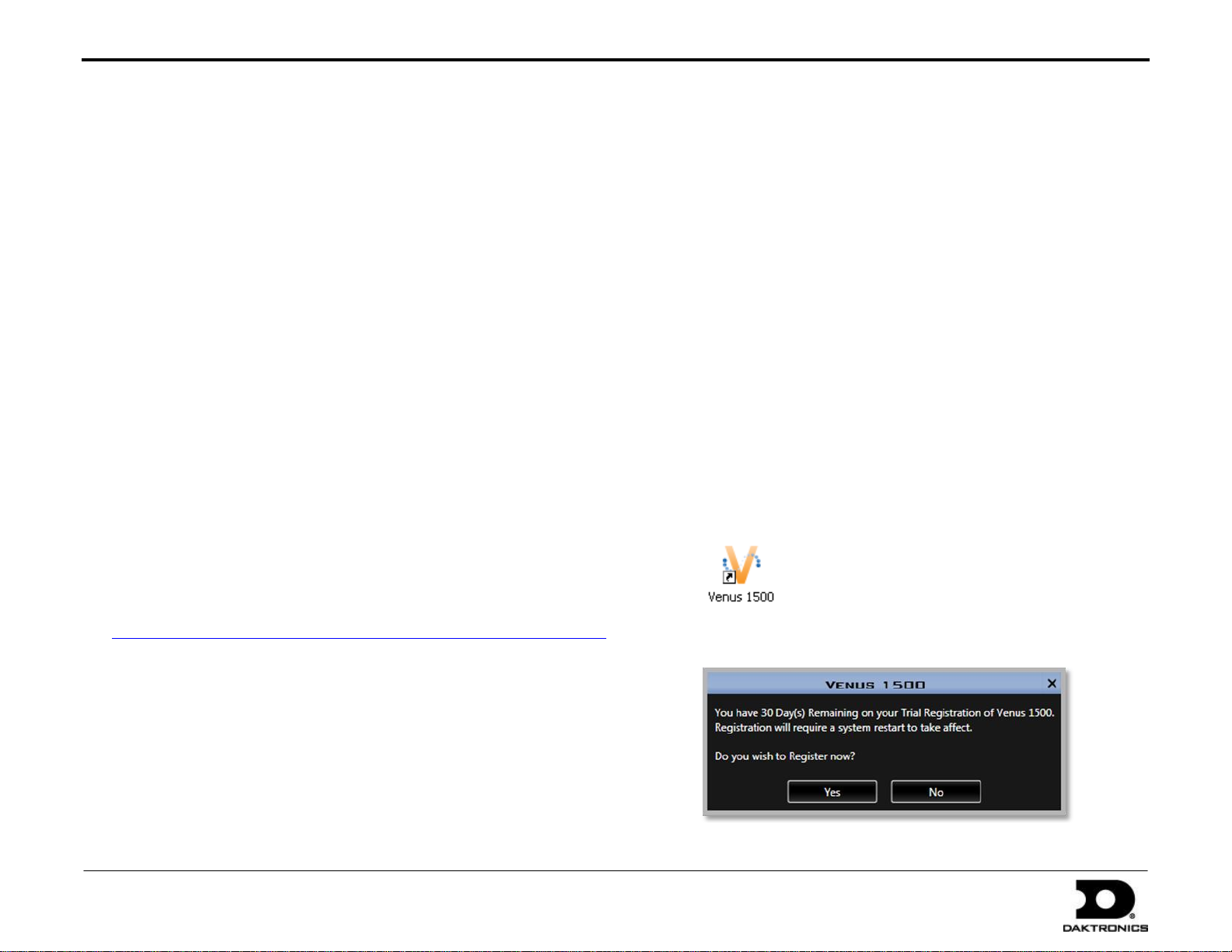
1. Double-click the Venus 1500 icon on the desktop.
2. You will be asked if you wish to register your software. Click No.
Page 2
DMP-1500/M3 (SS & ST) Setup With Show Control Quick Guide 2 of 11
201 Daktronics Drive PO Box 5128, Brookings, SD 57006
Tel: 1-800-325-8766 or 605-697-4300 Fax: 605-697-4746
Website: www.daktronics.com
DD1805670 Rev 11
2 July 2012
Hub
Button
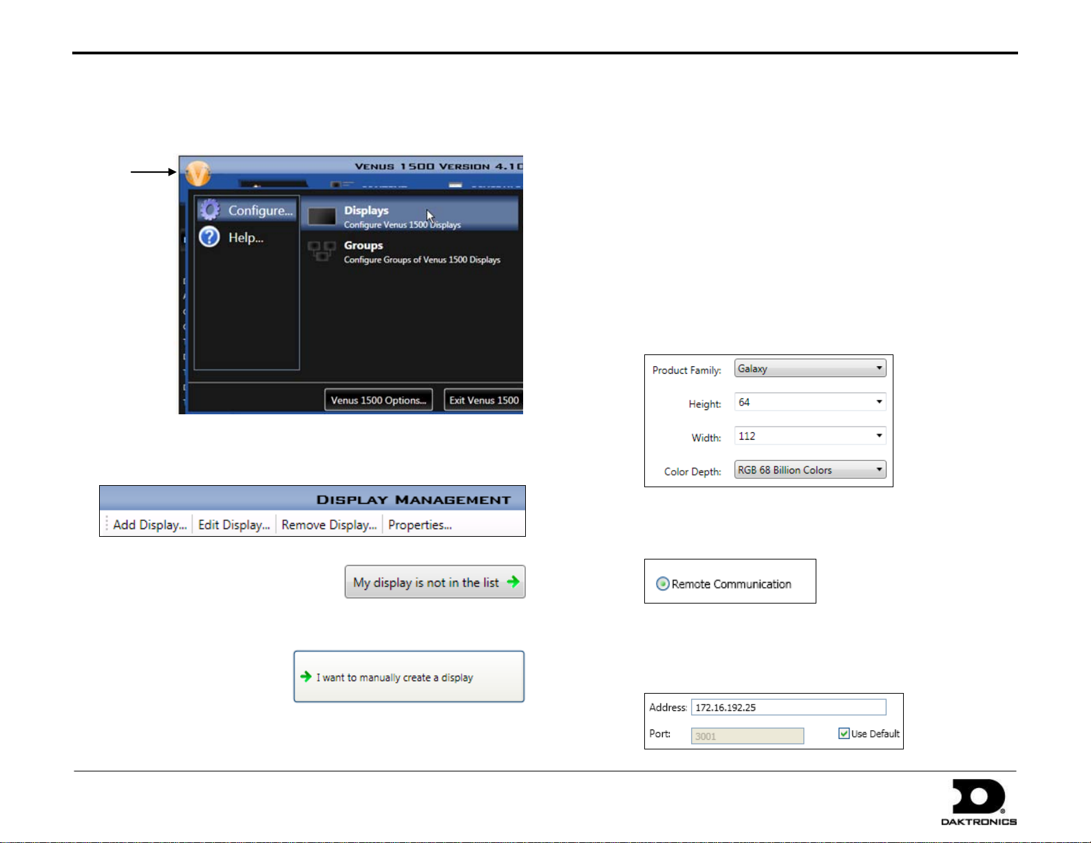
3. On the Venus 1500 main window, click on the Venus 1500 Hub button,
then go to Configure > Displays.
4. In the Display Management Window, click Add Display to start the
Configuration Wizard.
5. The sign may or may not be detected
and displayed in the Configuration
Wizard window. DO NOT select it.
Instead, click My display is not in the list.
6. In the Display Creation
window, click I want to
manually create a display.
7. In the Display Configuration window, use the following settings:
Product Family: Galaxy
Height: The height in pixels of the display (see previous page)
Width: The width in pixels of the display (see previous page)
Color Depth: RGB 68 Billion Colors
Note: ST-2014 scorer’s tables have a height of 32 and a width of
144, while ST-2016 tables have a height of 64 and a width of 288.
The total width will be multiplied by the number of tables that
are being used as a single display face.
Click Continue when finished.
8. In the Communication Types window, select Remote
Communication and then click Continue.
9. In the Remote Communication window, type in Address
“172.16.192.25”. Make sure Use Default is checked, and then
click Continue.
Page 3
DMP-1500/M3 (SS & ST) Setup With Show Control Quick Guide 3 of 11
201 Daktronics Drive PO Box 5128, Brookings, SD 57006
Tel: 1-800-325-8766 or 605-697-4300 Fax: 605-697-4746
Website: www.daktronics.com
DD1805670 Rev 11
2 July 2012
Note: 172.16.192.25 represents the default IP address that M3
controllers are assigned at the factory. If your display will be
assigned a different IP address on your facility’s network, either (a)
enter that IP address into the appropriate fields when creating the
display, if available, or (b) after the display is installed, refer to
Changing a Display’s IP Address.
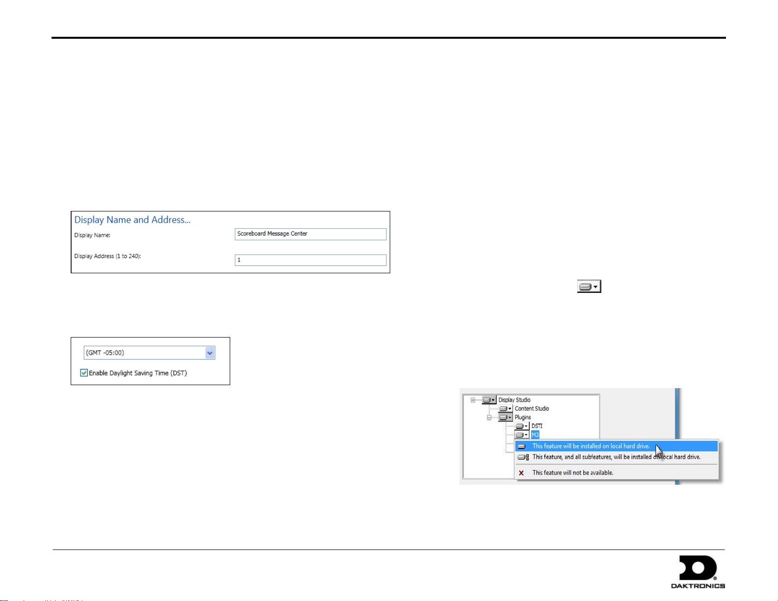
10. In the Display Settings window, type in a descriptive Display Name, and
type in a Display Address from “1” to “240” (typically “1”). Click
Continue when finished.
11. In the Set Time Zone window, select the correct time zone from the
dropdown list, and select whether to use Daylight Saving Time (DST).
Click Continue when finished.
12. In the Create Another Display window, click No.
13. In the Summary window, review the display settings. Click Finish if the
settings are correct or click Back to Start and begin from Step 5.
At this point Venus 1500 can be closed. Continue to Show Control
Installation.
Show Control System Installation
Installing Via CD
1. Insert the Show Control System (SCS-2000) installation CD into the
CD-ROM drive (typically “D:\”).
2. The software installer should launch automatically. If it does not,
press the Windows key [] + [E] and double-click your CD-ROM
drive. Double-click the “Current Version” folder and then doubleclick on the “Display Studio Setup.exe” file.
3. When the Welcome screen appears, click Next.
4. In the License Agreement window, select I accept the terms in the
license agreement, and then click Next.
5. In the Database Server window, leave the default database server
selection intact (“[Your computer name]\NUCLEUS”), and then
click Next.
6. In the Plugins window, use the button to designate which
plugins should be installed on your computer. The following plugins
should be set to This feature will be installed on local hard drive:
Display Studio
Content Studio
DSTI
M3
Note: Set any other plugins to This feature will not be available.
7. When finished, click Next.
Page 4
DMP-1500/M3 (SS & ST) Setup With Show Control Quick Guide 4 of 11
201 Daktronics Drive PO Box 5128, Brookings, SD 57006
Tel: 1-800-325-8766 or 605-697-4300 Fax: 605-697-4746
Website: www.daktronics.com
DD1805670 Rev 11
2 July 2012
Hub
Button
8. At the Ready to Install the Program window, click Install. The status of the
installation process can be monitored in this window.
9. After installation is complete, click Finish to exit the installer.
Click Yes to restart the computer (if prompted).
Note: A license is required to use Show Control software. Call or email
Daktronics as shown when the software is first opened to activate the
product. For more information refer to DD1785842.
Display Studio Service Configuration
Note: If you have already created your display in Venus 1500 Version 4, the
steps in this section aren’t necessary; however, the Service Configuration
window can be used to confirm that your display was successfully registered
with the Nucleus Server. Until a network connection is established with your
display, the display’s Status will appear as No Response.
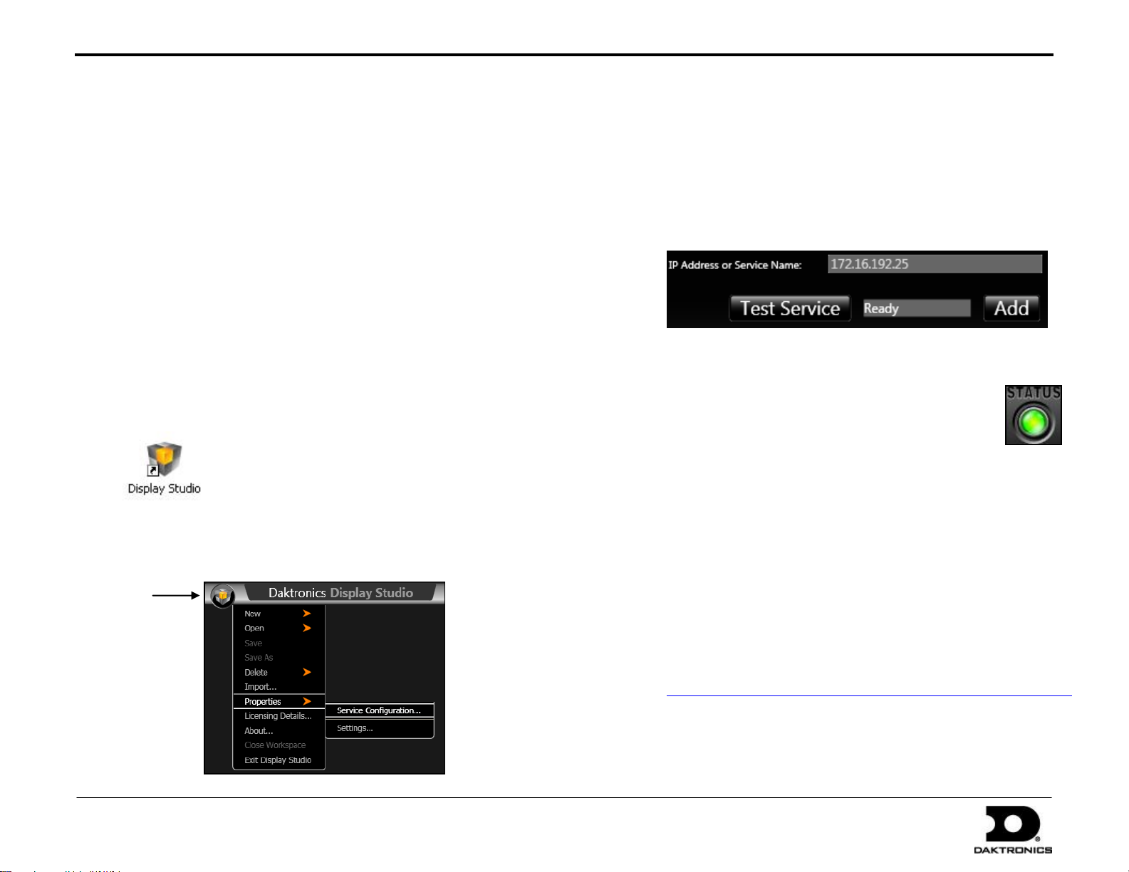
1. Double-click the Display Studio icon on the desktop:
2. Click the Display Studio Hub button in the upper-left corner of
the application screen, and then go to Properties > Service
Configuration.
3. In the IP Address or Service Name box, type in “172.16.192.25”.
Note: This is the default address. If the address must be
changed, refer to Changing a Display’s IP Address.
4. Click Test Service. The box should show that the sign is
“Ready”.
5. Click Add, and the sign will move to the list below.
6. Click OK to exit the Service Configuration.
7. The Status button in the lower-left corner of the
Display Studio application screen should be green:
If the status is red, there is at least one error. Click the button to
see a description of the error(s). A common issue is that a folder
SCS is trying to read from is not shared with full permissions
(right-click the folder and select Properties; click the Sharing
tab, enable Share this folder, then click OK).
At this point you begin creating content for the display. Pages 5-7
explain how to create and play content. Refer also to the Show
Control Training CD (Daktronics part number 0A-1453-0038) to get
familiarized with Display Studio and Content Studio.
Note: The SCS training video is also available online at
www.daktronics.com/Support/Training/ShowControlSystem/.
Page 5
DMP-1500/M3 (SS & ST) Setup With Show Control Quick Guide 5 of 11
201 Daktronics Drive PO Box 5128, Brookings, SD 57006
Tel: 1-800-325-8766 or 605-697-4300 Fax: 605-697-4746
Website: www.daktronics.com
DD1805670 Rev 11
2 July 2012
Creating Content
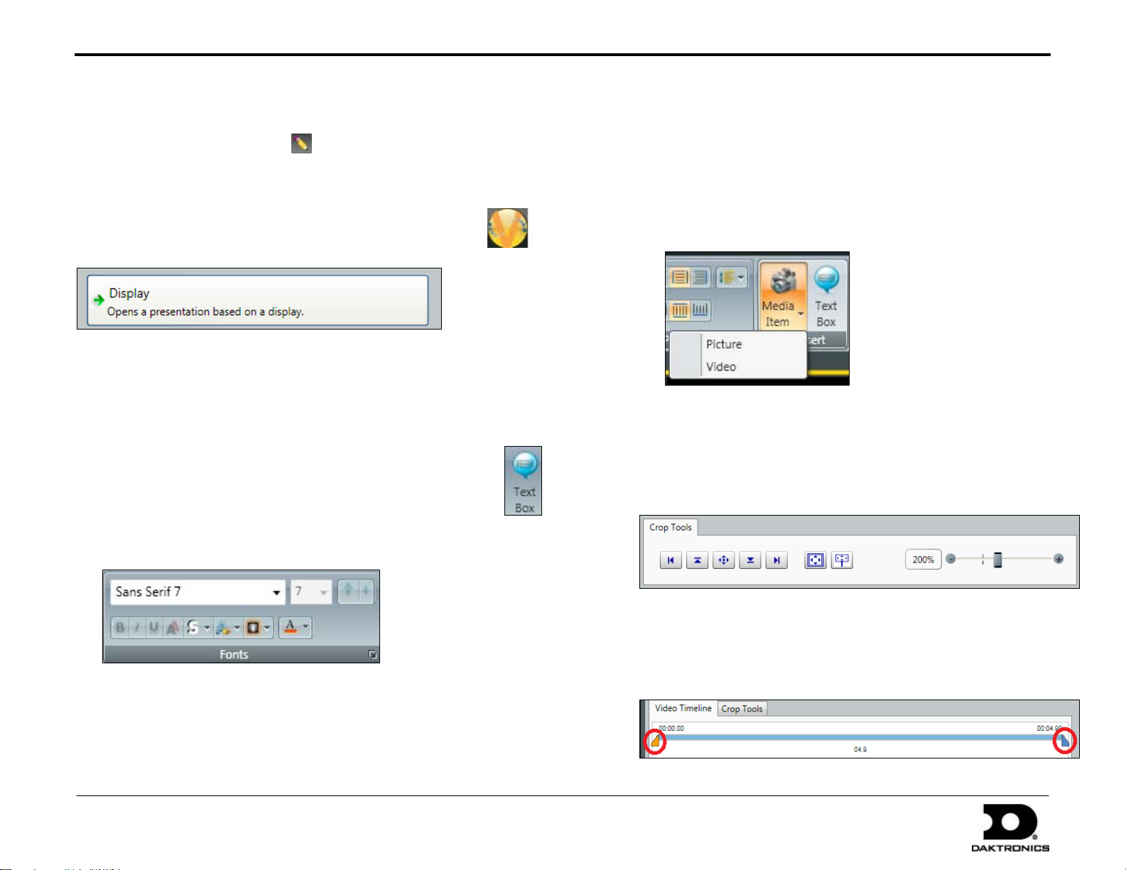
In Display Studio, click the pencil button in the upper-right corner of the
application screen to launch Content Studio.
Creating Presentations
1. Click the Content Studio Hub button, and then click New.
2. In the window that appears, click Display.
Note: If you have multiple displays, select the display from the list and
click Next.
A new blank presentation will open.
Adding Text
1. On the Home tab, in the Quick Insert section, click Text Box.
2. Click and drag to create a new text box.
3. Type your message inside the text box, and then highlight it
(press [Ctrl] + [A]).
4. Use the tools in the Fonts section to format the text.
5. When finished, click outside of the text box. To move the text box, simply
click and drag it. To resize the text box, use the little green squares.
To select multiple text boxes, hold [CTRL] while clicking on them.
Adding Images & Video
Supported file types are as follows:
Images: *.bmp; *.png; *.jpg; *.jpeg; *.gif; *.tif; *.psd; *.tiff
Video: *.avi, *.mp4, *.mpg, *.mpeg
Note: 8 and 32-bit videos are not supported.
1. On the Home tab, in the Quick Insert section, click Media Item.
2. Click on Picture or Video, depending on the file type to import.
3. Browse to the file that you would like to insert, and click Open.
4. In the Import window, you can crop the image/video by dragging
the blue squares on the edges of the image or by using the Crop Tools
at the bottom of the window.
When importing a video, you will also have the option to crop the
length of the video using the orange and blue sliders at either end of
the Video Timeline. Use the Play, Pause, and Stop buttons to
preview the video clip.
Page 6
DMP-1500/M3 (SS & ST) Setup With Show Control Quick Guide 6 of 11
201 Daktronics Drive PO Box 5128, Brookings, SD 57006
Tel: 1-800-325-8766 or 605-697-4300 Fax: 605-697-4746
Website: www.daktronics.com
DD1805670 Rev 11
2 July 2012
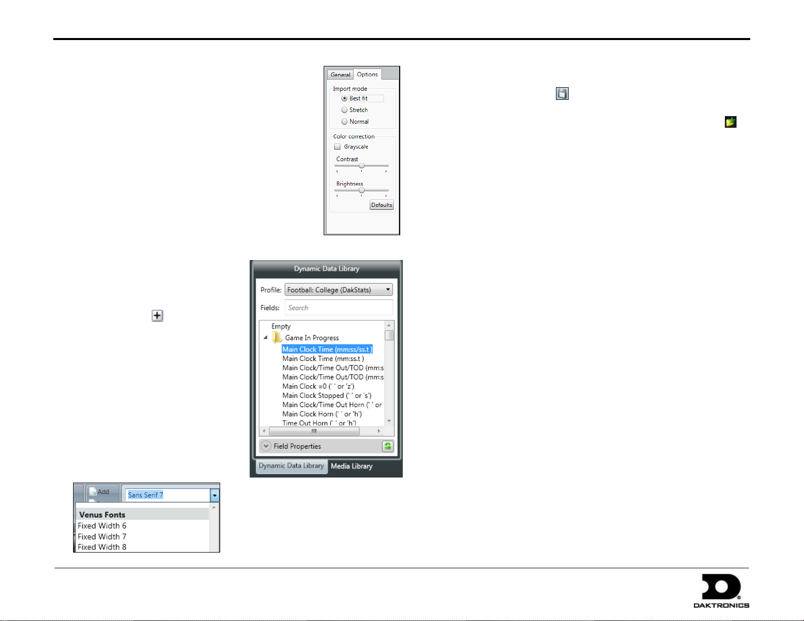
5. For more settings, click the Options tab on the
right side of the window. Here you can adjust the
Import mode, Color correction, Contrast, and
Brightness. To restore the image to its original
settings, click Defaults.
6. Click Import when finished.
7. If you want the image or video to be used for the
background and it imports in front of the content:
a. Right-click on the image.
b. Go to Order > Send to Back.
Adding Real-Time Data (RTD)
1. Click the Dynamic Data Library tab.
2. In the Profile drop-down list, select
the desired sports profile.
3. After selecting the Profile, folders of
data fields related to that profile
appear. Click the buttons to view
all of the the fields contained within
each folder.
4. Click and drag the desired data field
into the presentation.
5. The data field may be formatted in
the same manner as a text box
(refer to Adding Text) with one
exception: at the bottom of the
fonts list, there is a section called
Venus Fonts. These are the only
fonts that can be used for RTD fields.
Saving the Presentation
1. Click the Save button .
2. In the Save As window, navigate to the folder in which you want to
save the presentation. You can click the Create New Folder
button if needed.
3. Enter a descriptive File name for the presentation and click Save.
Note: Files with RTD cannot be saved to a display’s root directory.
Files must be saved inside a folder, either “Default” or a folder of
your own creation. Also, it is not possible to create new folders
within the “Default” folder.
Importing SS Media Kit Content
1. Insert the SS SCS Content Kit flash drive (Daktronics part number
0A-1539-2106) into an available USB port.
2. Press the Windows key [] + [E]. Double-click the flash drive, and
then double-click the Importing SS Media Kit Content PDF and
follow the instructions.
Playing Content
After creating content in Content Studio, you must return to Display
Studio to set up buttons to play your content.
Creating a New Workspace
1. Click the Display Studio Hub button in the upper-left corner of the
application screen, and then go to New > Workspace.
2. Type in a descriptive Name for the workspace, and then click Save.
Page 7

DMP-1500/M3 (SS & ST) Setup With Show Control Quick Guide 7 of 11
201 Daktronics Drive PO Box 5128, Brookings, SD 57006
Tel: 1-800-325-8766 or 605-697-4300 Fax: 605-697-4746
Website: www.daktronics.com
DD1805670 Rev 11
2 July 2012
Next
Plays the next item in the Queue
Blank
Sign
Blanks the display, stops playback of the Queue,
and clears the Queue
Clear
Queue
Clears the Queue, but allows the current item to
keep playing
Loop
If enabled, queue plays through items continuously
until stopped or given another command
Creating a Quick Display Container
1. Right-click within a workspace page.
2. Go to New > Quick Display Container.
3. Select the desired display from the Display Name drop-down list.
4. Click Save. The other container settings can be adjusted later.
Note: To create quick display buttons for all the content in an entire
library, click Link to Library, select the Library folder, and click Open.
Display Studio will automatically create buttons for each piece of
content. Note that the container must be empty to be linked to a library.
Copying Files to the Player
Files must be copied to the player before they can be displayed.
1. In Display Studio, click the button to expand the M3 File Manager.
2. Verify that the display
you are managing is
selected in the dropdown list.
3. In the Database Files box,
select the file(s) you
wish to copy to your
digital media player.
4. Click the arrow
button to copy the
selected file(s) to your
player. Files which
appear in the Player
Files box will be capable
of being played on the
selected display.
Display Queue
Creating a Quick Display Button
1. Right-click within the quick display container, and select New Button.
2. Click Add and browse to a file to
associated with the button.
3. Select the file, and click Open.
4. Click Add to include more files, or
click to remove files.
5. The button will take the name of
the first file added to it. Type in a
new name for the button in the
text box if desired.
6. Click Save when finished.
Click the Show Queue button in the top-right corner of a Quick
Display Container to reveal the Queue. Here you can see the playlist and
total remaining time for each clip. Use the buttons at the bottom of the
Quick Display Container to manage the Queue:
Page 8

DMP-1500/M3 (SS & ST) Setup With Show Control Quick Guide 8 of 11
201 Daktronics Drive PO Box 5128, Brookings, SD 57006
Tel: 1-800-325-8766 or 605-697-4300 Fax: 605-697-4746
Website: www.daktronics.com
DD1805670 Rev 11
2 July 2012
DCS Installation (Track Timing)
The Daktronics Communication Server (DCS) is typically only required when displaying Real Time Data (RTD) for track events.
1. Insert the Daktronics Communication Server (DCS) installation CD
(Daktronics part number 0A-1453-0035) into the CD-ROM drive
(typically “D:\”).
2. Press the Windows key [] + [E]. Double-click your CD-ROM drive,
and then double-click the “dcs3” file.
3. Follow the onscreen instructions to complete the installation.
4. Once the installation is complete, double-click the
shortcut icon on the desktop to run the program.
An icon will also appear in the taskbar.
Note: After the initial installation, each time the computer is started,
DCS should begin running automatically (visible in the taskbar).
5. Click the Ports button on the left-hand side of the window:
6. Double-click Port 5. The Port Configuration window will open.
Configure Port 5 as follows:
Name: must be “Output”
Type: UDP/IP Socket
Port: “3002”
Click Advanced>> and set the Mode to Transmit only.
Leave all other settings as is; click OK when finished.
7. Double-click Port 2. The Port Configuration window will open
again. Configure Port 2 as follows:
Name: “Hy-tek” or another descriptive name
Type: Serial Port
Port: COM1* (may vary depending on the exact COM port
available on the computer)
Baud: 19200
Leave all other settings as is; click OK when finished.
Page 9

DMP-1500/M3 (SS & ST) Setup With Show Control Quick Guide 9 of 11
201 Daktronics Drive PO Box 5128, Brookings, SD 57006
Tel: 1-800-325-8766 or 605-697-4300 Fax: 605-697-4746
Website: www.daktronics.com
DD1805670 Rev 11
2 July 2012
8. Click the Active Files button on the left-hand side of the window.
9. Right-click in the area that says No items to display, and then select
Insert File.
10. In the Insert Active File window:
Put a checkmark in the box next to Port 2.
Click the […] button and browse to “C:\Program Files
(x86)\Daktronics\DCS\Scripts\Custom” and select
“OffsetStandardRTD5000.dds”
Click OK when finished.
When data is sent from Hy-tek, it should now go out to the display. If
there is more than one Ethernet connection configured on the computer,
for example one wireless and one wired, you may need to disable the
unused network, or change the order of preference to ensure that the
information is delivered to the desired network.
A second possibility is to direct the data to a specific display address
when configuring the UDP/IP Output Port:
Note: To ensure that DCS recognizes each COM port, try to have
all USB-to-serial adapters connected before the computer is
turned on. If DCS did not recognize a COM port (evident by
going to the Ports screen in DCS and seeing a red indicator next
to the Serial Port): go back to the Control screen, click Stop,
count to ten, and then click Start.
Port 3 and Port 4 can be configured to receive data from another
source, for example a FinishLynx Capture station with a dedicated
results output, or a FinishLynx Edit station. On the Insert Active File
window (see previous page), the “OffsetStandardRTD10000.dds”
and “OffsetStandardRTD15000.dds” files would need to be set to
Port 3 and Port 4, respectively.
For more information on setting up track interfaces, refer to the
Track and Field Interfaces Setup Guide (ED14511), available online
at www.daktronics.com/manuals.
Page 10

DMP-1500/M3 (SS & ST) Setup With Show Control Quick Guide 10 of 11
201 Daktronics Drive PO Box 5128, Brookings, SD 57006
Tel: 1-800-325-8766 or 605-697-4300 Fax: 605-697-4746
Website: www.daktronics.com
DD1805670 Rev 11
2 July 2012
Changing a Display’s IP Address
Displays are set up by default with a Static IP address of 172.16.192.25. In some cases, this will need to be changed. It is recommended to use the
facility’s existing network whenever possible. In order to set up the display, the Show Control computer should have IP address 172.16.192.20 with a
subnet mask of 255.255.255.0.
6. Enter the following settings:
Using Existing Network
When using a facility’s existing network, the “static” IP addresses of each
display will be provided by the Network Administrator at the facility.
The Show Control computer will just need to connect to the same network in
order to control the displays.
Set IP Address of the Display
First you must obtain IP address with Subnet Mask for each display from the
facility’s Network Administrator. Then you will use M2Config to set the IP
address of each display as follows:
1. Open a web browser, and go to the following address:
dakfiles.daktronics.com//downloads/venus1500/utils/M2_Config/
2. Click on “setup.exe”, and Save this file directly to the Show Control
computer, or to a USB flash drive.
3. On the Show Control computer, double-click the “setup.exe” file, and
follow the onscreen instructions to install M2Config.
4. Browse to “C:\Program Files (x86)\Daktronics\M2Config” and double-
click the “M2Config” file.
5. Go to Network > Configure Connection or click the Configure
Connection button.
Type: TCP/IP.
Address: Input the
correct address for the
display (typically “1”)
IP Address:
“172.16.192.25”
Socket: Leave Use
Default (3001) checked
unless using a serial
server with a socket
number other than “3001”.
Click OK when finished.
7. Press [F2] to connect to the display.
8. Once connected to the display, click on the Communications folder
and then TCP/IP on the Configuration tab.
9. Enter the IP Address, Subnet mask, and Default gateway as provided by
Network Administrator.
10. Press [F7] to apply the settings.
Page 11

DMP-1500/M3 (SS & ST) Setup With Show Control Quick Guide 11 of 11
201 Daktronics Drive PO Box 5128, Brookings, SD 57006
Tel: 1-800-325-8766 or 605-697-4300 Fax: 605-697-4746
Website: www.daktronics.com
DD1805670 Rev 11
2 July 2012
11. After the display has rebooted, close all the open M2 Configuration
windows and use the Venus 1500 software to connect to the display
(refer to Venus 1500 Installation & Configuration).
12. Now change the IP address of the Show Control computer using the
Network Administrator’s recommended settings.
Using a Daktronics Router
The display(s) must be set up to obtain their IP Addresses automatically.
In most cases, the router will be used to create a network separate from
the facility’s; the router may be configured to connect to such a network.
Note: Do not connect the router to the facility’s network without
reconfiguring it. Refer to the router’s documentation for instructions
on connecting to a facility network.
1. Follow steps 1-8 under Using Existing Network.
2. Click Obtain an IP address automatically.
3. Enter any descriptive DHCP Name (Ex: “East16x112”,
“Primary16x112”, etc.).
4. Press [F7] to apply the settings.
5. Verify all computers on the network are set to obtain IP Address
automatically:
a. Press the Windows key [] and click on Control Panel.
b. Click on Network and Sharing Center.
c. Click Local Area Connection.
d. Click Properties.
e. Double-click on Internet Protocol Version 4 (TCP/IPv4).
f. Verify that Obtain an IP address automatically is selected.
System Riser Diagrams
Refer to the attached drawings for typical layouts of display
communication methods.
Indoor, Wire Ethernet: DWG-835248
Indoor, Fiber Ethernet: DWG-835283
Indoor, Ethernet Bridge Radio: DWG-1065120
Outdoor: Fiber Ethernet: DWG-836336
ST-2014: DWG-808072
ST-2016: DWG-1044507
Control Setup, ST-2014/16: DWG-1037213
For additional system riser diagrams featuring RTD integration
and wireless Ethernet setups, refer to DD1562468.
For More Information
To learn more about the Daktronics Show Control System
software, consult the Show Control System User Handbook,
which is accessible via either of the following options:
Press the Windows key [] and go to All Programs >
Daktronics > Display Studio > Show Control System
User Handbook.
From within Display Studio, press the Display Studio
Hub button and select Help.
For any other questions, comments, or concerns, please contact
Daktronics Support Services.
United States & Canada
Toll Free: 1-800-DAKTRONICS (1-800-325-8766)
Outside the U.S. & Canada
+1-605-697-4000
Page 12

Page 13

DAKTRONICS
Page 14

DAKTRONICS
Page 15

Page 16

Page 17

Page 18

 Loading...