

Page 1

Petroleum Price Displays
DF-4000 Series
Installation and Operation Manual
ED-16084 Rev 0 – 15 March 2006
Page 2

ED-16084
Project-1356
Rev 0 – 15 March 2006
Please fill in the information below for your DataMaster display and controller;
use it for reference when calling Daktronics for assistance.
Display Serial No. _____________________________________________
Display Model No. _____________________________________________
Date Installed _________________________________________________
DataMaster Serial No. __________________________________________
DAKTRONICS, INC.
Copyright © 2006
All rights reserved. While every precaution has been taken in the preparation
of this manual, the publisher assumes no responsibility for errors or
omissions. No part of this book covered by the copyrights hereon may be
reproduced or copied in any form or by any means – graphic, electronic, or
mechanical, including photocopying, taping, or information storage and
retrieval systems – without written permission of the publisher.
DataMaster
Other trademarks used in this manual are the property of their
respective owners.
™
and DataTime® are trademarks of Daktronics, Inc.
Page 3

i
Table of Contents
Section 1: Introduction....................................................................................1-1
1.1 How To Use This Manual ......................................................................... 1-1
Important Safeguards: ........................................................................ 1-1
1.2 Daktronics Nomenclature..........................................................................1-2
1.3 Manual Overview...................................................................................... 1-3
1.4 Product Overview......................................................................................1-4
1.5 Model Names.............................................................................................1-5
1.6 Product Safety Approval ........................................................................... 1-5
Section 2: Petroleum Price Display Specifications......................................2-1
2.1 Shop Drawings..........................................................................................2-1
2.2 Specifications ............................................................................................ 2-2
Section 3: Mechanical and Electrical Installation ........................................3-1
3.1 Electrical installation................................................................................. 3-1
Power.................................................................................................. 3-1
3.2 Power and Signal Connection ...................................................................3-3
Address Dip Switch Settings..............................................................3-4
Section 4: Display Maintenance and Troubleshooting................................4-1
4.1 Cabinet Specifications............................................................................... 4-1
4.2 Component Location and Access..............................................................4-1
4.3 Schematics.................................................................................................4-2
4.4 LED Drivers .............................................................................................. 4-2
4.5 Troubleshooting......................................................................................... 4-3
4.6 Lightning Protection..................................................................................4-4
4.7 Replacement Parts ..................................................................................... 4-5
4.8 Daktronics Exchange and Repair and Return Programs............................4-6
Section 5: Controller options (DM 100).........................................................5-1
5.1 DataMaster 100 Overview......................................................................... 5-1
Replacement Parts List.......................................................................5-2
5.2 Control System Overview ......................................................................... 5-2
5.3 Controller Signal Connection.................................................................... 5-4
5.4 DataMaster Insert and Code...................................................................... 5-6
5.5 Rate Display Operation ............................................................................. 5-6
Rate Display Startup........................................................................... 5-7
Menu Items......................................................................................... 5-9
Rate Display Controller Operation...................................................5-10
Modifying Price Line Settings..........................................................5-10
Display Option ................................................................................. 5-11
Modem Settings................................................................................ 5-12
Table of Contents
Page 4

Display Status...................................................................................5-13
Set Time............................................................................................5-15
Dimming...........................................................................................5-16
Update Display.................................................................................5-17
Section 6: Controller options (RC-50)........................................................... 6-1
6.1 RC-50 Rate Display Operation..................................................................6-1
6.2 Rate Display Operation..............................................................................6-1
Editing the Display.............................................................................6-1
Section 7: Controller options (RC-100)......................................................... 7-1
7.1 RC-100 Rate Display Operation................................................................7-1
7.2 Wireless Specific Considerations ..............................................................7-1
7.3 Rate Display Operation..............................................................................7-1
Rate Display Startup...........................................................................7-1
New Code Key ...................................................................................7-2
Rate Display Controller Operation.....................................................7-3
Modifying Price Line Settings............................................................7-3
Display Sequence ...............................................................................7-4
Menu Items.........................................................................................7-4
LED Test ............................................................................................7-4
Display Option....................................................................................7-5
Display Status.....................................................................................7-6
Set Time..............................................................................................7-7
Dimming.............................................................................................7-8
Appendix A: Reference Drawings.........................................................................A-1
Appendix B: DataMaster Frequently Asked Questions (FAQ)...........................B-1
ii Table of Contents
Page 5

i
List of Figures
Figure 1: Daktronics Drawing Label .................................................................................. 1-1
Figure 2: Display Identification Label................................................................................1-2
Figure 3: DF-4000 Petroleum Price Display.......................................................................1-4
Figure 4: Driver...................................................................................................................3-4
Figure 5: DF-4000, Front view with face panels open .......................................................4-1
Figure 6: DataMaster 100 ...................................................................................................5-1
Figure 7: DataMaster 100 Controller with Signal Cable.....................................................5-3
Figure 8: Wire Control from Base of Sign..........................................................................5-4
Figure 9: Wire Control from Building Location.................................................................5-5
Figure 10: DataMaster 100 Insert, LL2551 ........................................................................ 5-6
Figure 11: RC-50 Controller...............................................................................................6-1
Figure 12: RC-100 Controller.............................................................................................7-1
List of Figures
Page 6

Page 7
Section 1: Introduction
This manual explains the installation and operation of Daktronics DataMaster™ Outdoor
LED Petroleum Price Displays and provides details for display maintenance. If you have
questions regarding the safety, installation, operation, or service of these systems, contact
Daktronics. Customer Service Help Desk telephone numbers are listed on the cover page of
this manual.
1.1 How To Use This Manual
Important Safeguards:
1. Read and understand these instructions before installing your display.
2. Do not drop the controller or allow it to get wet.
3. Properly ground the display with a ground rod at the sign location.
4. Disconnect power when the display is not in use.
5. Disconnect power when servicing the display.
6. Do not modify the display structure or attach any panels or coverings
without the express written consent of Daktronics, Inc.
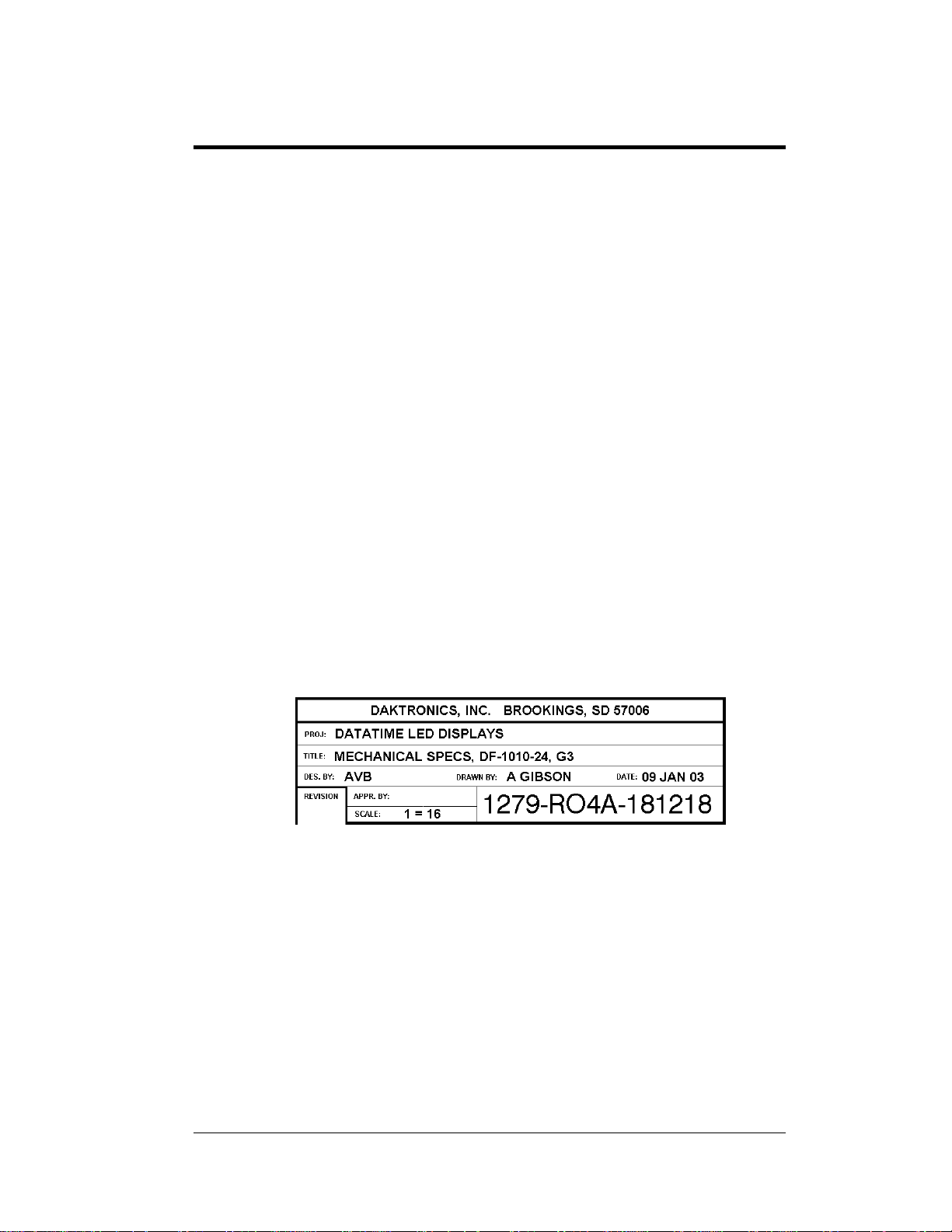
Figure 1, below, illustrates the Daktronics drawing numbering system. Daktronics
identifies individual drawings with a number (1279-RO4A-181218 in the example),
which is located in the bottom right corner of each drawing. This manual refers to
drawings by the last set of numbers in their ID as well as the letter preceding them.
The example would be Drawing A-181218.
Figure 1: Daktronics Drawing Label
Reference drawings in this manual are grouped and inserted in alphanumeric order
in the Appendix.
Listed below are a number of drawing types commonly used by Daktronics, along
with the information each is likely to provide.
System Riser Diagrams: overall system layout from control room to
display, power, and phase requirements.
Shop Drawings: fan locations, transformer locations, mounting
information, power and signal entrance points, and access method (front or
rear).
Introduction 1-1
Page 8

Schematics: power wiring, signal wiring, panelboard or power termination
panel assignments, signal termination panel assignments, and transformer
assignments.
Final Assembly: component locations, part numbers, display dimensions,
and assembly/disassembly instructions.
All references to drawing numbers, appendices, figures, or other manuals are
presented in bold typeface, as in this example: “Refer to Drawing A-181220 for the
location of the driver enclosure.” Additionally, any drawings referenced within a
particular subsection are listed at the beginning of that subsection in the following
manner:
Reference Drawing:
Mechanical Specs, DF-1020-13, G3.....................Drawing A-181220
Daktronics identifies manuals by their engineering document (ED) number, which is
located on the cover page of the manual. For example, this manual would be referred
to as ED-16084.
The serial and model numbers of a Daktronics display can be found on the ID label
on the display. The label will be similar to the one shown in Figure 2. When calling
Daktronics Customer Service, please have this information available to ensure that
your request is serviced as quickly as possible. For future reference, note your
display model number, serial number, and installation date on the front page of this
manual.
Figure 2: Display Identification Label
Daktronics displays are built for long life and require little maintenance. However,
from time to time, certain display components will have to be replaced. The
Replacement Parts List in Section 4 provides the names and part numbers of
components that may require replacement during the life of this display.
Following the Replacement Parts List is an explanation of Daktronics exchange and
replacement programs. Refer to these instructions if you must replace or repair any
display component.
1.2 Daktronics Nomenclature
To fully understand some Daktronics drawings, such as schematics, it is necessary to
know how various components are labeled in those drawings. You will find this
information useful when trying to communicate maintenance or troubleshooting
efforts.
1-2 Introduction
Page 9

The label “A” on a drawing item typically denotes an assembly. An assembly can be
a single circuit board or a collection of components that function together, usually
mounted on a single plate or in a single enclosure.
In addition, the following labeling formats might be found on various Daktronics
drawings:
“TB _ _” denotes a termination block for power or signal cable.
“E _ _” denotes a grounding point.
“J _ _” denotes a power or signal jack.
“P _ _” denotes a power or signal plug for the opposite jack.
Finally, Daktronics part numbers are commonly found on drawings. Those part
numbers can be used when requesting replacement parts from Daktronics Customer
Service. Take note of the following part number formats. (Not all possible formats
are listed here.)
“0P- _ _ _ _- _ _ _ _” denotes an individual circuit board, such as a driver
board.
“0A-_ _ _ _ - _ _ _ _” denotes an assembly, such as a circuit board and the
plate or bracket to which it is mounted. A collection of circuit boards
working as a single unit may also carry an assembly label.
“W- _ _ _ _ ” denotes a wire or cable. Cables may also carry the assembly
numbering format in certain circumstances. This is especially true for
ribbon cables.
“T- _ _ _ _ ” denotes a transformer.
“PR- _ _ _ _ _ - _” denotes a specially ordered part.
“M- _ _ _ ” denotes a metal part, and “0M-_ _ _ _ _ _” typically denotes a
fabricated metal assembly.
1.3 Manual Overview
This manual details outdoor LED numeric displays. It is divided into the following
sections:
Section 1: Contains an overview of the DataMaster Series, product safety
information, and labeling and numbering descriptions.
Section 2: Lists petroleum price display drawings with mechanical and
electrical information and contains a table detailing the mechanical
specifications, circuit specifications and power requirements for
each model.
Section 3: Contains information needed to perform the mechanical and
electrical installation for each model.
Section 4: Contains service and troubleshooting information.
Section 5: Contains an overview of the DataMaster controller, with a
description of the types of control systems and instructions for
DM 100 setup.
Section 6: Contains an overview of the RC-50 controller, with a description
of the types of control systems and instructions for RC-50 setup.
Introduction 1-3
Page 10

Section 7: Contains an overview of the RC-100 controller, with a description
of the types of control systems and instructions for RC-100 setup.
Appendix: Contains all drawings referenced in this manual, quick-start
guides, and a list of frequently asked questions.
1.4 Product Overview
DataMaster Petroleum Price displays are part of a family of Daktronics products
designed for easy installation, readability, and reliability. Microprocessor control
assures consistent operation and accuracy. The DF-4000 Series model Petroleum
Price display is illustrated in Figure 3 below.
Figure 3: DF-4000 Petroleum Price Display
The DataMaster Series includes:
Petroleum Price Displays: Standard petroleum price displays in the US
employ a 9/10 fraction. International models (DF-4000 series) typically
have four full digits and a decimal.
The Petroleum Price displays are available in two styles, a full-cabinet model
designed for standalone use (DF-4100), and a front-insertion, or “drop-in”, model
designed for installation in an existing or custom sign (DF-4000).
DataMaster displays use light emitting diodes to illuminate their numeric digits.
(Light emitting diodes, or LEDs, are tiny, solid-state components that use a
semiconductor to transform electrical current into light; they are high-intensity, lowenergy lighting units.)
The displays feature highly visible PanaView
front-insertion Petroleum Price model is available with 10", 13", and 18" digits.) All
DataMaster displays are configured with red or amber LEDs.
Because of their LED technology, the displays consume little power, some barely
more than a household lamp. Power usage for individual displays in this series is a
maximum 150 W. All models have an option of 120 V or 240 V.
DataMaster cabinets, specially developed for outdoor use, are constructed of heavygauge aluminum. Digit faceplates are black, and they are set directly into the surface
of the display. Mounting weights and dimensions for each model are listed in
Section 2 of this manual.
®
digits 10", 13", and 18" tall. (The
1-4 Introduction
Page 11

The DataMaster outdoor LED displays have been designed for use with a
DataMaster
system, or the RC-50 mini remote control. All controller devices use a keyboard
overlay (called an insert) for display control.
™
100 hand-held controller. Also available is a radio controlled RC-100
1.5 Model Names
Daktronics displays, video screens, and scoreboards are differentiated by their model
numbers. The displays described in this manual all carry the two-letter prefix, DF-,
which indicates that they are DataMaster models. The letter D indicates that they are
numeric displays; the letter F indicates outdoor LED technology.
In the outdoor LED display series, typically the first set of numbers following the
prefix identifies the series or product line, while the second set of numbers refers to
digit height. A final letter denotes digit color. With Model DF-4000-13-A, for
example, 4000 identifies the Petroleum Price full-cabinet line, and 13 signifies that
the display’s primary digits are a nominal 13" tall. In the example, the letter A
signifies that the digits are amber, while R would indicate red, and G green LED
digits.
1.6 Product Safety Approval
Daktronics outdoor displays are ETL and UL listed and tested to CSA standards for
outdoor use. Contact Daktronics with any questions regarding the testing procedures.
Introduction 1-5
Page 12

Page 13
Section 2: Petroleum Price Display
Specifications
2.1 Shop Drawings
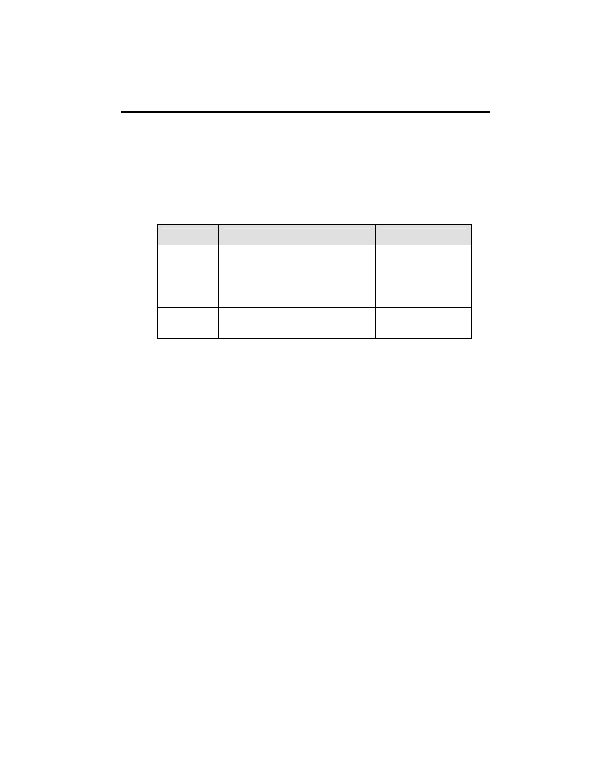
Use the following table to determine the mechanical specifications for your display.
The drawings are listed below by model number; they have been inserted in the
Appendix in alphanumeric order by drawing number.
Model Drawing Title Drawing Number
DF-4000-10 Shop Drawing, DF-4000-10-X-NA-DI Drawing B-260455
DF-4000-13 Shop Drawing, DF-4000-13-X-NA-DI Drawing B-258389
DF-4000-18 Shop Drawing, DF-4000-18-X-NA-DI Drawing B-258025
Gasoline Price
Display Specifications
2-1
Page 14

2.2 Specifications
The table below shows all of the mechanical specifications, circuit specifications,
and maximum power requirements for each model in this series. Models are listed in
alphanumeric order by digit size.
DataMaster Petroleum Price Displays
Model Dimensions
DF-4000-10-A
DF-4000-10-R
DF-4000-10-G
DF-4000-13-A
DF-4000-13-R
DF-4000-13-G
DF-4000-18-A
DF-4000-18-R
DF-4000-18-G H1’-10", W4’-9", D0’2"
H1’-3", W3’-6", D0’2"
(381 mm, 1067 mm,
51 mm)
H1’-6", W4’-0", D0’2"
(457 mm, 1219 mm,
51 mm)
H1’-10", W4’-9", D0’2"
(559 mm, 1448 mm,
51 mm)
(559 mm, 1448 mm,
51 mm)
Weight
35 lb (16 kg) 10"
40 lb (19 kg) 13"
45 lb (20 kg) 18"
45 lb (20 kg) Green 144 W 120 V AC
Digit
Size/Color
(254 mm)
Amber, red,
green
(330 mm)
Amber, red,
green
(457 mm)
Amber, red,
green
Maximum
Power
72 W
72 W
72 W
Circuit
120 V AC
15 A
120 V AC
15 A
120 V AC
15 A
15 A
2-2
Gasoline Price
Display Specifications
Page 15

Section 3: Mechanical and Electrical
Installation
Mechanical installation typically consists of inserting the DF-4000 into an opening in a large
sign, and securing with screws.
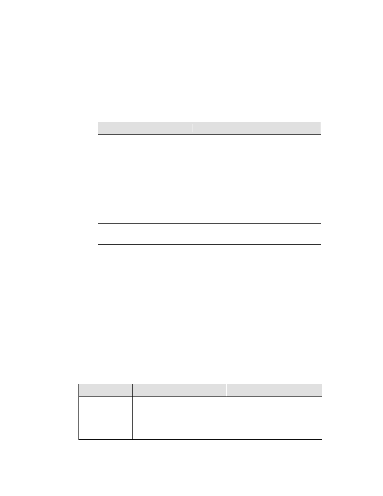
Electrical installation consists of the following processes:
Providing power and ground to a disconnect near the display.
Routing power and ground from the main disconnect to the power connection
pigtail in the display.
Connecting the display ground to a grounding electrode at the sign location.
Routing the control signal cable from the control location to the sign location.
3.1 Electrical installation
Reference Drawing:
RC-50 Quick Install Guide ...........................................Drawing A-257189
Address Dip Switch Settings........................................Drawing B-256001
Each Shop Drawing shows details on Installation and access for electrical and signal
connections. Example: B-260453 explains all power needs in the notes and the
picture below shows details.
Note: Only qualified individuals should perform power routing and
termination to the display. It is the responsibility of the electrical contractor
to ensure that all electrical work meets or exceeds local and national codes.
Power
Reference Drawings:
Wiring Schematic, DF-2000/4000 Series ...........................Drawing A-263988
Daktronics DataMaster displays have been designed for easy access to components,
and the power and control signal hookup has been simplified. Front panels are
removable or hinged to allow access to the digits, cabling, and other electronic
components.
Correct power installation is imperative for proper display operation. The
subsections that follow give details of display power installation. Only qualified
individuals should attempt to complete the electrical installation; untrained personnel
should not attempt to install these displays or any of the electrical components.
Improper installation could result in serious damage to the equipment and could be
hazardous to personnel.
The DataMaster outdoor displays require a dedicated, 120 V circuit for incoming
power. The display itself has no breakers or fuses.
Mechanical and 3-1
Electrical Installation
Page 16

WARNING: It is critical that the display circuit be fused at 15 A, and that all
conductors used must be designed to pass a 15 A current in normal operation.
Failure to meet wiring and over current protection device requirements is a
violation of the National Electrical Code
®
and will void the display warranty.
Refer to the DataMaster display schematics listed below and to the chart in Section 2
to determine circuit specifications and maximum power requirements for the models
described in this manual.
Grounding
Reference Drawings:
Wiring Schematic, DF-2000/4000 Series...........................Drawing A-263988
Displays MUST be grounded according to the provisions outlined in Article 250
of the National Electrical Code and according to the specifications in this
manual. Daktronics recommends a resistance-to-ground of 10 ohms or less.
The contractor performing the electrical installation can verify ground
resistance. Technicians from Daktronics Sales and Service offices can also
provide this service.
The display system must be connected to an earth electrode installed at the display.
Proper grounding is necessary for reliable equipment operation. It also protects the
equipment from damaging electrical disturbances and lightning. The display must
be properly grounded, or the warranty will be void. Refer to the schematics,
Drawing A-263988. Connection for power wires and ground wire is made to
supplied harness pigtails inside the display. Standard NEC color code applies. (black
= hot, white = neutral, green/yellow = ground).
The material for an earth-ground electrode differs from region to region and may
vary according to conditions present at the site. Consult the National Electrical Code
and any local electrical codes that may apply. The support structure of the display
cannot be used as an earth-ground electrode. The support is generally embedded in
concrete, and if it is in earth, the steel is usually primed or it corrodes, making it a
poor ground in either case.
Power Installation
There are two considerations for power installation: installation with ground and
neutral conductors provided, and installation with only a neutral conductor provided.
These two power installations differ slightly, as described in the following
paragraphs:
Installation with Ground and Neutral Conductors Provided
For this type of installation, the power circuit must contain an isolated earth-ground
conductor. Under this circumstance, do not connect neutral to ground at the
disconnect or at the display. This would violate electrical codes and void the
warranty. Use a disconnect so that all hot lines and neutral can be disconnected. The
3-2
Mechanical and
Electrical Installation
Page 17

National Electrical Code requires the use of a lockable power disconnect within
sight of or at the display.
Installation with Only a Neutral Conductor Provided
Installations where no grounding conductor is provided must comply with Article
250-32 of the National Electrical Code. If the installation in question meets all of the
requirements of Article 250-32, the following guidelines must be observed:
• Connect the grounding electrode cable at the local disconnect, never at
the display driver/power enclosure.
• Use a disconnect that opens all of the ungrounded phase conductors.
3.2 Power and Signal Connection
Reference Drawings
Address Dip Switch Settings........................................Drawing B-256001
Power connects to the pigtail inside the display. The pigtail has three wires: black
(120 V AC line), white (neutral) and green (ground), and a 5-pin plug on one end.
The plug is connected to the mating plug on the transformer. Use wire nuts to
connect power wires to the pigtails.
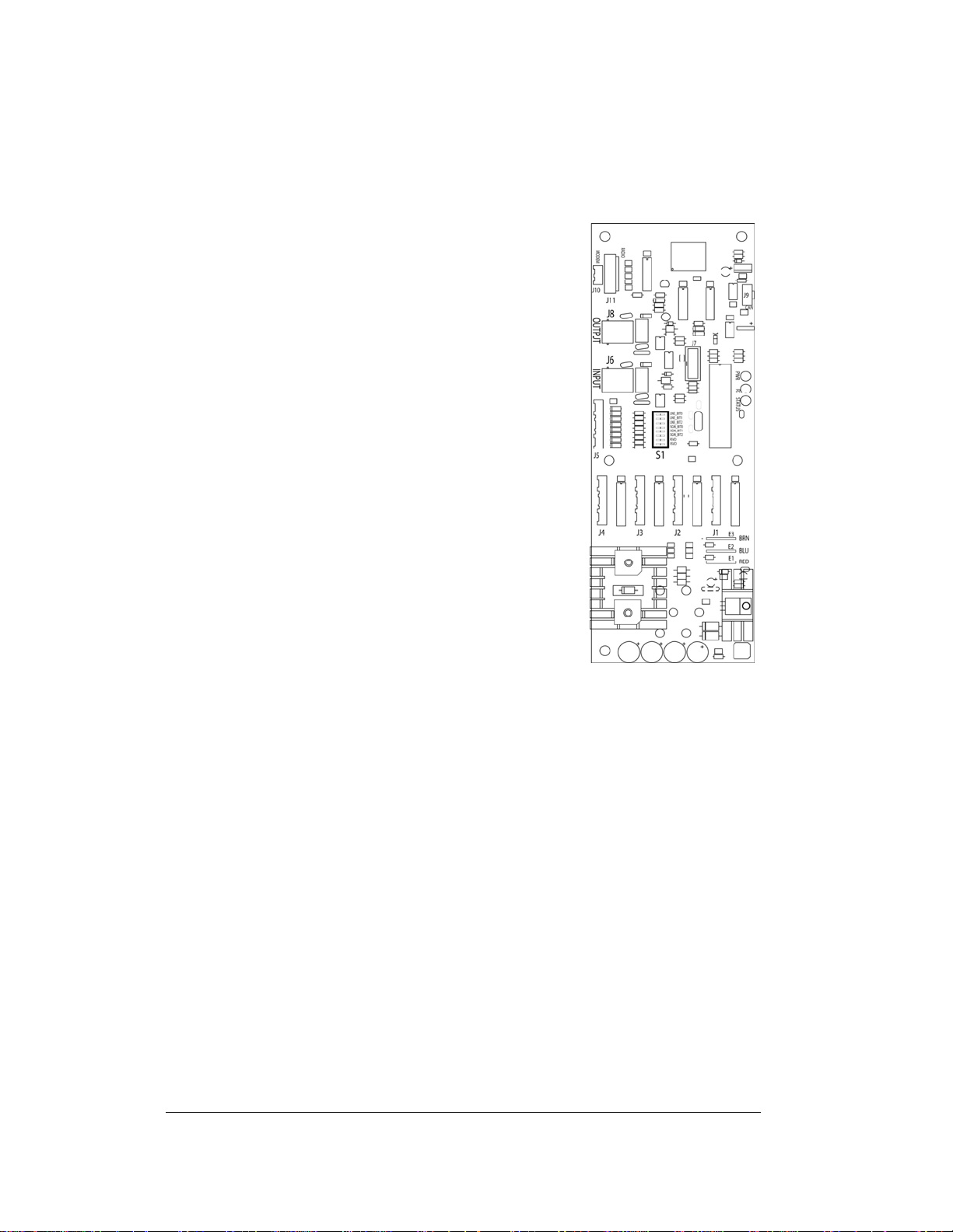
Signal wires are terminated with a telephone-type RJ14 connector. Route the cable
from the jack in the j-box to J6 in the driver (see Figure 4 below).
Mechanical and 3-3
Electrical Installation
Page 18
Address Dip Switch Settings
Reference Drawings:
Address Dip Switch Settings ....................................... Drawing B-256001
One driver at each sign installation is designated as the
“host driver.” This driver receives its signal directly
from the controller on the Signal In connector “J6.” The
Signal Out connector “J8” is used to connect to “client
drivers.” Other connectors used for communication are
“J11” (Radio, RC-100 system) and “J12” (RC-50
receiver). With the DM-100 and the RC-100, every sign
acts as a host and every driver has its own light sensor.
With the RC-50, the host receiver sends a signal
through J12, and sends the line information out to the
clients.
Every driver, either host or client, must have a unique
address. The address is set by moving the switches in an
eight position to the “Dip switch,” located on the dr iver.
Addresses allow the user to set up to eight lines in up to
eight sign groups. All displays with the same line
number will show the same price. Refer to
Drawing B-256001 for an illustration of the client/host
driver setups and for a line number and sign chart.
Figure 4: Driver
3-4
Mechanical and
Electrical Installation
Page 19
Section 4: Display Maintenance
and Troubleshooting
IMPORTANT NOTES:
1. Disconnect power before doing any repair or maintenance
work on the display!
2. Allow only qualified service personnel access to internal
display electronics.
3. Disconnect power when not using the display.
4.1 Cabinet Specifications
Cabinets for the Daktronics outdoor LED digit displays are constructed of heavygauge aluminum. Exact dimensions and weights for each model are listed in the
chart in Section 2. Hinged panels for servicing digits and indicators and for
component access are detailed in each model's mechanical specifications drawing.
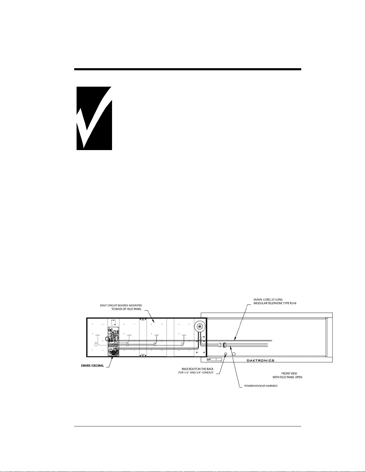
4.2 Component Location and Access
For the front-access modules in this series, all internal electronic components and
digits can be reached by opening the hinged access door on the front of the display.
The door swings left when the two latches on the front edge are opened, as shown in
Figure 5. For front and opened views of the displays, refer to your model's Shop
drawings, listed in Sections 2.1.
Figure 5: DF-4000, Front view with face panels open
Maintenance and 4-1
Troubleshooting
Page 20
Component placement varies slightly with each DataMaster model; consult the
model-specific mechanical drawing to determine the layout for your display.
Note: Disconnect power before servicing the display! Disconnect power, too,
when the display is not in use. Prolonged power-on may shorten the life of
some electronic components.
4.3 Schematics
Reference Drawings:
Specifications; Gas Price Driver, 4 Col......................... Drawing A-250728
Wiring Schematic, DF-2000/4000 Series ............................Drawing A-263988
Drawings A-263988 is the schematic diagram and Drawings A-250728 is the
Driver Specification Diagram for the driver used in the DataMaster Petroleum Price
displays. The schematic includes power and signal inputs and all wiring for the
models described in this manual.
4.4 LED Drivers
Reference Drawings:
Specifications; Gas Price Driver, 4 Col......................... Drawing A-250728
In the display, the LED drivers perform the task of switching digits on and off. Refer
to Drawings A-250728 for a complete listing of driver connector functions and
wiring pin numbers.
Connector No. Function
J1 – 4 Digits
J5 Not loaded
J6 CL Input
J7 Program
J8 CL Output
J9 Not loaded
J10 Modem
4-Column LED Driver
J11 Radio
J12 RC-50 Input
4-2
Maintenance and
Troubleshooting
Page 21
4.5 Troubleshooting
This section lists potential problems with the display, indicates possible causes, and
suggests corrective action. This list does not include every possible problem, but it
does represent some of the more common situations that may occur. (Refer to the
appropriate manual for a list of potential problems with add-on or separately
mounted message centers.
Symptom/Condition Possible Cause
Garbled display
Digit will not light
Segment will not light
Segment stays lit
Data appears in the wrong place
on the display, wrong data on a
particular line of the display
Internal driver logic malfunction
Control console malfunction
Broken black wire to digit
Poor contact at driver connection
Driver malfunction
Broken LED or connection
Driver shift register failure
Broken wire between driver and digit
Poor contact at driver connector
Driver shift register failure
Short circuit on digit
Incorrect address settings on drivers
(Refer to “Power On Self-Test” in the
following section, and consult tables to set
correct addresses.)
Some DataMaster displays have their own built-in troubleshooting mechanism.
Failures that may occur in the display driver are described using codes. In the event
a sign malfunctions, a failure code registers by displaying an “Ex” value on the first
two digits of the display. “E” simply indicates an error, and the letter “x” represents
the actual code number. Refer to the following table for a description of each failure
code and for possible solutions.
Note: The LCD screen on the DataMaster 100 controller will not show the
failure codes described in the table below. Failure codes will only be
displayed on the DataMaster sign.
Failure Code Description Possible Solution
E4 No Message Error: This code is
shown when there are no
messages downloaded to the
display
Download a new message to the
display using the <
DISPLAY
100 controller.
> key on the DataMaster
UPDATE
Maintenance and 4-3
Troubleshooting
Page 22

4.6 Lightning Protection
The use of a disconnect near the display to completely cut all current-carrying lines
significantly protects the circuits against lightning damage. The National Electrical
Code also requires it. In order for this device to provide protection, the power must
be disconnected when the display is not in use. The control console should also be
disconnected from power and from the signal j-box when the system is not being
used. The same surges that may damage the display’s driver can also damage the
console’s circuit.
4-4
Maintenance and
Troubleshooting
Page 23

4.7 Replacement Parts
Refer to the following table for Daktronics replacement parts.
Description
Daktronics
Part No.
RC-50 Radio with overlay 0A-1356-0064
Antenna A-2015
Receiver card 0P-1192-0355
Transformer, wall pack T-1118
RC-100 hand held assembly 0A-1110-0046
RC-100 Price Display insert LL-2617
DataMaster 100 hand-held controller 0A-1196-0088
Junction box, outdoor, 9-pin D-male 0A-1196-0093
Junction box, indoor, 9-pin D, male 0A-1196-0099
DataMaster 100 outdoor wired installation kit 0A-1356-0002
DataMaster 100 indoor wired installation kit 0A-1356-0105
Toroid Transformer, Display T-1124
Digit cable, 1 ft. W-1575
Digit cable, 3 ft. W-1576
Gas Price Driver, 4-col 0P-1356-0002
Signal Surge Card 0P-1356-0001
Decimal / Driver, red 0P-1192-0353
Decimal / Driver, amber 0P-1192-0355
Decimal / Driver, green 0P-1192-0354
Digit, 10" 7-segment, red, 14 pin 0P-1192-0356
Digit, 10" 7-segment, amber, 14 pin 0P-1192-0359
Digit, 10" 7-segment, green, 14 pin 0P-1192-0357
Digit, 13" 7-segment, red, 14 pin 0P-1192-0347
Digit, 13" 7-segment, amber, 14 pin 0P-1192-0348
Digit, 13" 7-segment, green, 14 pin 0P-1192-0349
Digit, 18" 7-segment, red, 14 pin 0P-1192-0341
Digit, 18" 7-segment, amber, 14 pin 0P-1192-0342
Digit, 18" 7-segment, green, 14 pin 0P-1192-0343
Maintenance and 4-5
Troubleshooting
Page 24

4.8 Daktronics Exchange and Repair and Return
Programs
To serve customers' repair and maintenance needs, Daktronics offers both an
Exchange Program and a Repair and Return Program. Daktronics' unique Exchange
Program is a quick, economical service for replacing key components in need of
repair. If a component fails, Daktronics sends the customer a replacement, and the
customer, in turn, sends the failed component to Daktronics. This not only saves
money but also decreases display downtime.
Daktronics provides these plans to ensure users get the most from their Daktronics
products, and it offers the service to qualified customers who follow the program
guidelines explained below. Please call the Help Desk – 877-605-4034 – if you have
questions regarding the Exchange Program or any other Daktronics service.
When you call the Daktronics Help Desk, a trained service technician will work with
you to solve the equipment problem. You will work together to diagnose the
problem and determine which exchange replacement part to ship. If, after you make
the exchange, the equipment still causes problems, please contact our Help Desk
immediately.
If the replacement part fixes the problem, package the defective part in the same box
and wrapping in which the replacement part arrived, fill out and attach the enclosed
UPS shipping document, and RETURN THE PART TO DAKTRONICS. In most
circumstances, you will be invoiced for the replacement part at the time it is shipped.
This bill is due when you receive it.
Daktronics expects immediate return of an exchange part if it does not solve the
problem. The company also reserves the right to refuse equipment that has been
damaged due to acts of nature or causes other than normal wear and tear.
If the defective equipment is not shipped to Daktronics within 30 working days from
the invoice date, it is assumed you are purchasing the replacement part, and you will
be invoiced for it. This second invoice represents the difference between the
exchange price and the full purchase price of the equipment. The balance is due
when you receive the second invoice. If you return the exchange equipment after 30
working days from the invoice date, you will be credited for the amount on the
second invoice, minus a restocking fee.
To avoid a restocking charge, please return the defective equipment within 30
days from the invoice date.
Daktronics also offers a Repair and Return program for items not subject to
exchange.
Return Materials Authorization: To return parts for service, contact your local
representative prior to shipment to acquire a Return Material Authorization (RMA)
4-6
Maintenance and
Troubleshooting
Page 25

number. If you have no local representative, call the Daktronics Help Desk for the
RMA. This expedites repair of your component when it arrives at Daktronics.
Packaging for Return: Package and pad the item well so that it will not be
damaged in shipment. Electronic components such as printed circuit boards should
be installed in an enclosure or placed in an antistatic bag before boxing. Please
enclose your name, address, phone number and a clear description of symptoms.
This is how to reach us:
Mail: Customer Service
Daktronics, Inc.
PO Box 5128
331 32nd Ave
Brookings SD 57006
Phone: Daktronics Help Desk: 877-605-1113 (toll free)
or 605-697-4034
Fax: 605-697-4444
E-mail: helpdesk@daktronics.com
Maintenance and 4-7
Troubleshooting
Page 26

Page 27

Section 5: Controller options (DM 100)
This section describes the DataMaster 100, the RC 50, and the RC 100.
5.1 DataMaster 100 Overview
Reference Drawing:
Address Dip Switch Settings........................................Drawing B-256001
The DataMaster
designed to operate Daktronics LED
DataMaster
controller, 6
encased in ABS plastic, making it a
durable and convenient control option.
The console’s liquid crystal display
(LCD) guides the user through the
operation of the system.
The DataMaster 100, identified by the
series number DM 100, can be configured
to display petroleum price, motel rates,
and time and temperature data. Refer to
Drawing B-256001 for information on
possible control options and connection
procedures.
Note: When your carrier delivers your
Daktronics order, open the
packages and inspect for shipping
damage such as rattles and dents. See that all equipment is included as shown
on the packing slip. Immediately report any deficiencies to Daktronics. Save
all packing materials for shipping if warranty repair or exchange is needed.
100 Series controller, shown in Figure 6, is a hand-held controller
displays. This lightweight
1
/4" high by 4 1/4" wide, is
Figure 6: DataMaster 100
Gas Price 5-1
Page 28

Replacement Parts List
The following is a list of possible replacement parts for the DataMaster 100
controller. When re-ordering a part, be sure to use its corresponding part number.
Wall pack transformer T-1118
DataMaster 100 controller 0A-1196-0088
Control Insert LL-2551
Cable, DB-9 male to DB-9 female, 10' W-1267
Refer to Section 4.8 for details concerning the Daktronics exchange and repair
programs.
Description Daktronics Part No.
5.2 Control System Overview
All of the displays in the LED DataMaster Series have three main control options:
direct wire, radio, and data download from a junction box at the sign. Refer to the
appropriate system riser diagram, listed above, for detailed instructions on control
system setup.
Note: This manual covers direct-wire installations only! For systems using modem
or radio communication, also refer to the following Daktronics manuals:
ED13953: DataMaster Modem Installation Manual
ED13894: DataMaster Radio Installation Manual
5-2
Maintenance and
Troubleshooting
Page 29

Wire Control
Reference Drawings:
Address Dip Switch Settings .........................................Drawing B-256001
For display systems using a base-of-sign
connection, the DataMaster 100
controller, shown with a connecting cable
in Figure 7, plugs directly into an outdoor
junction box, where the operator keys in
instructions for the sign. Typically, the
j-box is mounted to the display pedestal or
column support. The controller draws its
power from the display itself. Refer to
Drawing B-256001 for complete details
on both indoor and outdoor direct-wire
installations.
Signal from the junction box enters the
sign and travels to the first display driver
over 2-pair, shielded signal cable. The 22
AWG cable must be enclosed in conduit.
Re-driven signal travels from the driver of
the first display to the driver of the next
Figure 7: DataMaster 100 Controller
with Signal Cable
over RJ14 flipped signal cable. The
process repeats for as many displays as
there are in the system.
Once instructions have been input into the display, the driver's memory retains the
data, and the controller can be unplugged. The sign will continue to operate on the
stored information.
Signal cabling is similar for systems where the DataMaster displays will be operated
remotely from a building location, except that the controller requires a wall pack
transformer. The transformer plugs into both the hand-held controller and into a 120
V AC outlet. The DataMaster controller also connects to a junction box to send
signal to the display, but the j-box will be located within the store or office. The
control location can be up to 2000 feet from the actual sign.
The operator changes the display by entering current prices, rates, and operating
instructions on the keypad of the DataMaster controller.
Gas Price 5-3
Page 30

5.3 Controller Signal Connection
Reference Drawing:
Address Dip Switch Settings Drawing B-256001
This section provides information on the setting up the signal connection between
the DM 100 and DataMaster Petroleum Price displays.
The DataMaster displays may be controlled from a location inside a building, or
from the base of the display, depending on customer preference. Drawing B-256001
and the subsections that follow provide greater detail on both installations using
signal wire.
Wire Control from the Base of the Sign
This control option, illustrated in
Figure 8, permits operation of the
sign from the base of the display. The
controller is connected to an outdoor
junction box mounted on the display
pole, which routes the signal to the
sign through one 2-pair cable, 22
AWG. Cable is in conduit where
required.
This control option does not require
the controller to be connected to a
power outlet. In this configuration,
the DataMaster 100 uses the sign as a
power source.
To operate the DataMaster display
using this setup, connect the 9-pin to
9-pin cable from the DataMaster
controller to the 9-pin j-box mounted
on the display pole.
Figure 8: Wire Control from Base of Sign
5-4
Maintenance and
Troubleshooting
Page 31

Wire Control from a Building Location
This control option, illustrated in Figure 9, permits operation of the sign from an
indoor control location. The handheld controller is connected to an indoor junction
box (j-box), which routes the signal to the sign through one 2-pair cable, 22 AWG.
Cable is in conduit where required.
To operate the
DataMaster display
using this setup, connect
the 9-pin to 9-pin cable
from the DataMaster
controller to the 9-pin
j-box, and plug the
controller's wall pack
transformer into a 120 V
AC outlet.
Figure 9: Wire Control from Building Location
Gas Price 5-5
Page 32

5.4 DataMaster Insert and Code
Reference Drawing:
Insert, LL-2551 Price/T&T Display .............................. Drawing A-164999
The DataMaster 100 uses a keypad insert to program rate information into
Daktronics LED DataMaster Rate Displays.
Figure 10 illustrates the DM 100 insert used to control the displays. For details refer
to Drawing A-164999.
If an insert is lost or damaged, a copy of the insert drawing located in Appendix A
can be used until a replacement is ordered.
To start the controller and use the insert, read the next section carefully to fully
understand the operation instructions.
5.5 Rate Display Operation
The DataMaster 100 controller can be configured to program price variances
displayed on the LED DataMaster Rate sign. The instructions provided in this
section discuss the functions the operator uses to control the Rate display. In the
unlikely event that the Rate Display malfunctions, refer to Appendix B for the
Frequently Asked Questions section for this display.
Connect the display with the DataMaster. Often
when using either a modem or radio an output jbox will also be connected for use if the other
means of communication fails.
Note: There is more than one way to get certain
LCD screens on the DM 100. One way is by
using the menu and then the arrows to reach
the desired programming location. The other
way is to set the first petroleum price and
then continue to enter through the additional
screens.
Figure 10: DataMaster 100 Insert, LL2551
5-6
Maintenance and
Troubleshooting
Page 33

Rate Display Startup
To operate the DataMaster Rate displays, the DataMaster 100 must first be
programmed to the rate display function. Use the <
startup. The following text will be displayed on the LCD during startup.
Daktronics, Inc.
Brookings, SD
DataMaster 100
ED-13374 VX.X
The controller will then list the “Current Function”, if it is Rate Display you can
continue, otherwise at the next frame: “Current Function? Press Set Function” you
need to press <
CLEAR/SET FUNCTION> and use the < ↑↓> to select Rate Display.
Note: Press the <
CLEAR/SET FUNCTION> key quickly to enter the function mode. If
you miss this step, unplug the power to the DataMaster controller and start
again.
Use the following table as a guide to startup procedures.
CLEAR/SET FUNCTION> key on
Gas Price 5-7
Page 34

LCD Screen Action
CURRENT
FUNCTION
RATE DISPLAY
CHANGE
FUNCTION?
PRESS SET
FUNCT
SELECT
FUNCTION
RATE DISPLAY
↓↑
Power is provided to the DM 100 through the
serial cable or through the wall pack
transformer, either directly or by way of the jbox/signal converter.
This display appears briefly.
This message appears next on the screen.
If “RATE DISPLAY” was shown on the bottom
line of the LCD during startup, do nothing. The
controller will automatically default to previous
Rate Display settings. (The controller will
remember the last function used, so you
should only have to do this with a new
controller or when switching between
DataMaster displays.)
If a function other than “RATE DISPLAY” was
shown on the bottom line of the LCD during
startup, press the <
the second LCD prompt is displayed.
You only have 1 or 2 seconds to push it. If you
miss it, unplug the power to the DM 100 and
try again.
Press the arrow up or down keys <
the rate display option is shown. Press the
ENTER> key to accept.
<
SET FUNCTION> key while
↑↓> until
Note: The actual Rate Price values will not be displayed on the DataMaster 100
LCD screen because these values are kept in the display itself.
5-8
Maintenance and
Troubleshooting
Page 35

Menu Items
Pressing the <MENU> key accesses the following settings:
1 Price Line 1
2 Price Line 2
3 Price Line 3
4 Price Line 4
5 Price Line 5
6 LED Test?
7 Display Option
8 Modem Settings
9 Display Status
10 Set Time 12HR
Use Menu items 1-5 to edit the price on each line of the display. Lines are typically
numbered top to bottom with 1 being the top of the display. For further details, refer
to Modifying Price Line Settings discussed previously in this section.
For more information about the Modem Settings submenu, refer to ED-13953:
DataMaster Modem Installation Manual. For additional information about the
Display Status or the Set Time submenus, refer to ED-13894: DataTime Radio
Installation Manual, that manual provides for complete details on installation and
setup for a bi-directional radio system.
Key Setting
Gas Price 5-9
Page 36

Rate Display Controller Operation
The DataMaster 100, configured to the rate display option, defaults to showing the
current display settings on power up. The following text will be shown on the LCD.
LCD Screen Action
LINE PRICE
1 ↓ $
DD.CC
<EDIT> TO
MODIFY
1 ↓ $
DD.CC
The display will toggle between these two
screens.
DD.CC = dollars and cents value shown on line
1.
Press the up or down arrow keys <
through the current setting for any of the lines
on the display.
Press the <
the line settings.
ENTER/EDIT> key to modify any of
↑↓> to scroll
Modifying Price Line Settings
The rate price can be modified either by pressing the <EDIT> key during operation
(Refer to the Rate Display controller operation) or using the <
the <
MENU> key operation.)
Use the following key to identify the item to be edited.
L = Current line number to be edited
DD.CC = Current dollars and cents value to edit
MENU> key (refer to
5-10
Maintenance and
Troubleshooting
Page 37

LCD Screen Action
LED TEST
ENTER TO
TEST
ENTER TO
TEST
CLEAR TO
EXIT
Display Option
Use the Display Option menu to select the display configuration.
LCD Screen Action
DISPLAY
OPTION
$00.00 ↓
Press the <ENTER> key to cycle the display
digits between all LEDs on and all LEDs off.
Press <ENTER> send the test command to the
sign.
Press <
The current configuration is shown on the
bottom line of the LCD. Press the down arrow
key to select any of the possible configuration
values.
Possible values are:
Select the configuration that matches the layout
of your display.
Note: If the wrong configuration is selected, the
digits shown on the LCD may not be displayed
correctly on the display.
Press <
next screen.
CLEAR> to exit the test mode
$00.00 (default)
$0.000
$.0000
$0000.00
$000.00
$00
ENTER> to accept and move on to the
Gas Price 5-11
Page 38

Modem Settings
The following items for a modem can be set using the DM 100:
Key Setting
1 Dial Number
2 Dial out prefix
3 Disconnect time
4 Multiple Dial
5-12
Maintenance and
Troubleshooting
Page 39

Display Status
The Display Status menu item can be used with a bi-directional display setup to get
display status back from the driver. The controller will cycle through various LCD
message screens, illustrated below and on the following page, that show display
status. Press <
LCD Screen Action
CLEAR> at any time to exit the Display Status submenu.
Display
status
Get status?
Driver
Firmware
version x.x
Current
day/time
mm/dd/yy
HH:MM
Last reset
time
Mm/dd/yy
hh:mm
Current temp
Xx ºf
TEMP SENSOR
OFFSET Xx ºC
Press <
connected to the DM-100.
The LCD will scroll through the status sent back from
the display. Following is a list of responses:
Firmware Version
Current Day/Time
Last Reset Time
Current Temp
Temp Sensor Offset
ENTER> to get the status of the display that is
This is the firmware version programmed on the host
MASC driver in the display.
This is the Day/Time value set in the driver. The time
format used will be 24-hour.
Note: To set the Day/Time, see the "Set Time"
section of your DataTime display system's
operation manual.
This time represents the last time the driver was
reset. Note that the time format used will be
24-hour.
This is the temperature read at the display by the
temp sensor. (This value does not include the offset,
if applicable).
This is the temp sensor offset value programmed
into the driver.
Gas Price 5-13
Page 40

5-14
Maintenance and
Troubleshooting
Page 41

LCD Screen Action
DIM level xx
0=dim
63=bright
DIMming mode
automatic
Dim Level
This is the intensity level of the display; 0 is the
dimmest setting, and 63 is the brightest setting.
Dimming Mode
This is the current mode of dimming used by the
display.
Automatic Dimming – The light sensor controls
dimming.
Manual Dimming – The DM 100 console is used to
enter all display dimming information.
Set Time
This allows you to set the time and date with the DM 100.
LCD Screen Action
SET TIME–
12HR
HH:MM AM ↓
After setting the time you will need to set the date. If the date is already correct,
enter through the date and press <
HH – Current hours value
MM – Current minutes value
AM – Current AM/PM setting (not shown when
24-hour time is selected)
Using the number keys, enter the Time in the
12-hour (or 24-hour) format. Press the down
arrow key <↓> to modify the AM/PM setting.
Note: The flashing asterisk shows the current
data being edited.
To save changes, press the <ENTER> key
when finished editing.
Press the <CLEAR> key to cancel changes.
ENTER> to send the time to the display.
Gas Price 5-15
Page 42

Dimming
The dimming level of the Rate display can be adjusted in two ways. A light sensor,
mounted on each driver, can detect the level of ambient light at the display location
and dim the sign's LEDs accordingly. This function is known as automatic dimming.
When the manual dimming function is selected, the LEDs remain at the same level
of brightness regardless of the level of light detected at the display.
To select either of these functions, press <
on the bottom line of the LCD.
LCD Screen Action
DIMMING>. The current setting is shown
DIMMING
AUTOMATIC ↓
Press the down arrow key <↓> to toggle
through dim settings:
Automatic – The display automatically dims
based on the light detected at the display
Manual – The display dimming level is set
manually. Once set, this value remains
regardless of the level of light detected at the
display.
If AUTOMATIC dimming is selected, the following LCD prompt will be
shown:
LCD Screen Action
SET AUTO
DIMMING
MAX INTENSITY?
Press the <ENTER/EDIT> key to edit the auto
dimming max intensity. This is the maximum
intensity that the display will use in full-bright
modes (during daylight hours).
Press <
dimming maximum setting.
CLEAR> to keep the current auto
5-16
Maintenance and
Troubleshooting
Page 43

The following LCD prompt is shown for either Manual or Automatic dimming
selections:
LCD Screen Action
INTENSITY
XX↓↑
ENTER TO SET
XX – Current intensity (1-16)
Max Intensity - 16
Press the up or down arrow key <↑↓> to modify
the current intensity of the display (Note: The
DataMaster must be connected to the display)
Press <
manual-dimming mode is selected, this will be
the new intensity for the display. If the
automatic dimming mode is selected, the
display will illuminate in full-bright mode, which
is the maximum intensity level.
ENTER> to accept this intensity. If the
Update Display
Once connected to the display with a j-box, radio, or modem, press
<UPDATE DISPLAY > to display the new sequence on the display. This button
will also allow for a preview of the new sequence on the LCD.
Gas Price 5-17
Page 44

Page 45

Section 6: Controller options (RC-50)
6.1 RC-50 Rate Display Operation
RC-50 Quick install Guide..................................................Drawing A-257189
6.2 Rate Display Operation
The RC-50 controller can control four unique prices on multiple signs. The
instructions provided in this section discuss the functions the operator uses to control
the rate display.
Editing the Display
To edit the price on the display, press and hold any button
for 5 seconds. When the sign is in Edit mode, the decimal
LEDs blink.
On the RC-50, each pair of buttons corresponds to a price
line on the display. Each line is numbered to indicate the
line it corresponds to.
Increasing the price
To increase the price by one cent, press [+] for the
corresponding line.
Note: Make sure the display is in Edit mode.
Decreasing the price
To decrease the price, press [-] for the corresponding line.
Note: Make sure the display is in Edit mode.
Turbo mode
To rapidly increase or decrease a price, press and hold the
button for the corresponding line.
Note: When a button is not pressed for more than 10 seconds, the display exits the
Edit Mode. The prices are saved and the display returns to its normal state.
Figure 11: RC-50
Controller
Gas Price 6-1
Page 46

Page 47

Section 7: Controller options (RC-100)
7.1 RC-100 Rate Display Operation
Price Display Insert LL-2617
System Riser Diagram; RC-100, DataMaster..............Drawing A-244838
7.2 Wireless Specific Considerations
Although multiple wireless handheld controllers may be
connected to a single wireless base station server, the rate
display application allows only one handheld device to be
connected at a time.
7.3 Rate Display Operation
The RC-100 controller can be configured to program price
variances displayed on the LED DataMaster Rate display.
The instructions provided in this section discuss the functions
the operator uses to control the rate display.
Rate Display Startup
To operate the DataMaster Rate displays, the RC-100 must
first be programmed to the rate display function.
Figure 12: RC-100 Controller
Gas Price 7-1
Page 48

New Code Key
To select a new Price Display option (Rate, Lottery, Gas), use the new code key.
This key is an alternate function, so the <ALT> key must first be pressed.
LCD Screen Action
Press Enter
to select a
new code
SELECT
FUNCTION
Rate Display
↓↑
Initializing
Display
Searching
for
Display
Press <ALT> then <NEW CODE> to select a
new price display function. Press <CLEAR> to
resume normal operation. Press <ENTER> to
select a new function. Use the <
to select the new price function and then press
<ENTER>.
Press the arrow up or down keys<↑↓> until the
rate display option is shown. Press the
ENTER> key to accept.
<
To accept a new function, the handheld
controller will send this information to the
display.
If the wireless base station cannot be found
the controller will not work. This may happen if
the controller is out of range or if the wireless
base station has no power.
↑↓> arrow keys
Note: The actual rate price values will not be displayed on the RC-100 LCD
screen because these values are kept in the display itself.
7-2 Gas Price
Display Operation
Page 49

Rate Display Controller Operation
The RC-100, configured to the rate display option, defaults to showing the current
display settings on power up. The following tex t will be shown on the LCD.
LCD Screen Action
LINE PRICE
1 ↓ $ D.CC
<EDIT> TO
MODIFY
1 ↓ $ D.CC
The display will toggle between these two
screens.
DD.CC = dollars and cents value shown on line
1.
Press the up or down arrow keys <
through the current setting for any of the lines
on the display.
Press the <
the line settings.
ENTER/EDIT> key to modify any of
↑↓> to scroll
Modifying Price Line Settings
The rate price can be modified either by pressing the <EDIT> key during operation
(Refer to the rate display controller operation) or using the <
the <
MENU> key operation.)
Use the following key to identify the item to be edited.
L= Current line number to be edited
DD.CC= Current dollars and cents value to edit
MENU> key (refer to
LCD Screen Action
EDIT LINE L
$ D.CC
Press any of the number keys to edit the price
value for this line.
Press <
press <
Note: The flashing asterisk on the LCD shows
Press the down arrow key <
next line, or press the <
next item or the previous one on the list.
ENTER> to accept the new value or
CLEAR> to abort the changes.
the current data being edited.
↓> to modify the
↑↓> keys to move to the
Gas Price 7-3
Page 50

Display Sequence
Once connected to the display with a j-box, radio, or modem, press
<
DISPLAY SEQUENCE> to display the new sequence on the display. This button will
also allow for a preview of the new sequence on the LCD.
Menu Items
Pressing the <MENU> key accesses the following settings:
1 Price Line 1
2 Price Line 2
3 Price Line 3
4 Price Line 4
5 Price Line 5
6 LED Test?
7 Display Option
8 Display Status
9 Set Time 12HR
Use Menu items 1-5 to edit the price on each line of the display. Lines are typically
numbered top to bottom with 1 being the top of the display
Key Setting
LED Test
Select menu item 6, LED test, by pressing menu and using the <↓>, to test the LED
digits on the display.
LCD Screen Action
LED TEST
ENTER TO
TEST
ENTER TO
TEST
CLEAR TO
EXIT
7-4 Gas Price
Display Operation
Press the <ENTER> key to cycle the display
digits between all LEDs on and all LEDs off.
Press <ENTER> send the test command to the
sign.
Press <
CLEAR> to exit the test mode.
Page 51

Display Option
Use the display option menu to select the display configuration.
LCD Screen Action
DISPLAY
OPTION
$ 0.00 ↓
The current configuration is shown on the
bottom line of the LCD. Press the down arrow
key to select any of the possible configuration
values.
Possible values are:
$00.00 (default)
$0.000
$.0000
$0000.00
$000.00
$000.0
$00
Select the configuration that matches the layout
of your display.
Note: If the wrong configuration is selected, the
digits shown on the LCD may not be
displayed correctly on the display.
Press <
next screen.
ENTER> to accept and move on to the
Gas Price 7-5
Page 52

Display Status
This will look for a bi-directional link to the display, and will allow you to send the
sequence changes. Select menu item 7, display status, for display status functions.
LCD Screen Action
Display
status
Get status
Press the <ENTER> key to get the display
status, or <CLEAR> to exit the menu.
Use the <↑↓> keys to select other display
functions.
If <ENTER> is pressed, the LCD will show
the following display items:
• Driver Firmware Version
• Current Day/Time
• Last Reset Time
• Current Temp
• Temp Sensor Offset
• Dimming Level
• Dimming Mode
• Temp Sensor Status
After pressing <ENTER> the get status menu will display:
7-6 Gas Price
Display Operation
Page 53

Display Passcode
LCD Screen Action
Display
Passcode
Ent to Exit
Display
Passcode
Old
code……………*
Display
Passcode
New
code……………*
Display
Passcode
Passcode set
Press the <ENTER> key to set or change the
passcode. Press <CLEAR> to exit the menu.
If there was an old passcode, then that must
be entered first before entering a new code.
Enter the new four-digit passcode, and press
<ENTER>.
The LCD will show Passcode Set, if it was
successful.
If the <CLEAR> key is pressed and entered
during this process, the new passcode will not
be set.
Detect Clients
LCD Screen Action
Detect
clients
Ent to
confirm
Clients
found 1
Is this
Press the <ENTER> key to detect the number
of client statuses on the system.
This is used so the send sequence key knows
how many clients there are for showing error
messages.
The LCD will show how many clients are
found. If the <YES> key is pressed, then that
is the number the console will use for showing
error messages if all expected clients did not
respond.
correct?
Set Time
This allows you to set the time and date with the RC-100.
Gas Price 7-7
Page 54

Dimming
The dimming level of the rate display can be adjusted in two ways. A
temperature/light sensor, mounted near the display, can detect the level of ambient
light at the display location and dim the sign's LEDs accordingly. This function is
known as automatic dimming. When the manual dimming function is selected, the
LEDs remain at the same level of brightness regardless of the level of light detected
at the display. To select either of these functions, press <
setting is shown on the bottom line of the LCD.
LCD Screen Action
DIMMING>. The current
DIMMING
AUTOMATIC ↓
SET AUTO
DIMMING
MAX INTENSITY?
Press the down arrow key <↓> to toggle
through dim settings:
Automatic – The display automatically dims
based on the light detected at the display
Manual – The display dimming level is set
manually. Once set, this value remains
regardless of the level of light detected at the
display.
Blank Sign – The display can be blanked out
without powering down. Refer to the blank sign
section for details.
Press the <ENTER/EDIT> key to edit the auto
dimming max intensity. This is the maximum
intensity that the display will use in full-bright
modes (during daylight hours.)
Press <
dimming maximum setting
CLEAR> to keep the current auto
7-8 Gas Price
Display Operation
Page 55

INTENSITY
XX↓↑
ENTER TO SET
XX – Current intensity (1-16)
Max Intensity - 16
DIMMING
BLANK SIGN
↓
BLANK THE
SIGN?
<ENT> YES
<CLR> NO
Press the up or down arrow key <↑↓> to
modify the current intensity of the display
(Note: The DataMaster must be connected to
the display)
Press <
manual dimming mode is selected, this will be
the new intensity for the display. If the
automatic dimming mode is selected, the
display will illuminate in full-bright mode, which
is the maximum intensity level.
Press <ENTER> to accept this option.
The next LCD dialog will ask whether you
want to blank the screen or escape. The LCD
toggles between Yes and No. Pressing
<CLR> resumes normal operation; pressing
<ENT> actually blanks the sign.
ENTER> to accept this intensity. If
Gas Price 7-9
Page 56

Page 57

Appendix A: Reference Drawings
The Daktronics drawing number is located in the bottom right corner of the drawing. Refer to
Section 1.1 for instructions on reading the drawing number.
Drawings in this manual are referenced by their last set of digits and the letter preceding
them. Drawings in this appendix are first listed in alphanumeric order; a second grouping lists
drawings by function.
A-Drawings (All Drawings)
Insert, LL-2551 Price/T&T Display.................................................................Drawing A-164999
System Riser Diagram, RC-100, DataMaster................................................Drawing A-244838
Specifications; Gas Price Driver, 4 Col..........................................................Drawing A-250728
RC-50 Quick Install Guide .............................................................................Drawing A-257189
Models, DF-4000 Drop In Displays................................................................Drawing A-259603
Wiring Schematic, DF-2000/4000 Series.......................................................Drawing A-263988
Address Dip Switch Settings..........................................................................Drawing B-256001
Shop Drawing, DF-4000-18-X-NA-DI.............................................................Drawing B-258025
Shop Drawing, DF-4000-13-X-NA-DI.............................................................Drawing B-258389
Shop Drawing, DF-4000-10-X-NA-DI.............................................................Drawing B-260455
Riser Diagram, Indoor Wired Control, Gas price Display...............................Drawing B-267067
Riser Diagram, Outdoor Wired Control, Gas price Display ...........................Drawing B-267090
Reference Drawings A-1
Page 58

Page 59

Appendix B: DataMaster Frequently Asked
Questions (FAQ)
DataMaster FAQ..............................................................................................ED-13481
Gasoline Price B-1
Quick Start Reference
Page 60

Page 61

Page 62

Page 63

Page 64

Page 65

Page 66

Page 67

Page 68

Page 69

Page 70

Page 71

 Loading...