

Page 1

Petroleum Price Displays
DF-2100 Series
Single-face 10" to 60"
Installation and Operation Manual
ED-16637 Rev 1 5 June 2007
Website: www. daktronics.com
Tel: 866-343-3122 Fax: 605-697-4444
331 32nd Ave PO Box 5128 Brookings SD 57006
Page 2

ED-16637
Project-1356
Rev 1 – 5 June 2007
Please fill in the information below for this DataMaster display and controller.
Use it for reference when calling Daktronics for assistance. Refer to the cover
page of the manual for Daktronics Customer Call Center contact information.
Display Serial No. _____________________________________________
Display Model No. _____________________________________________
Date Installed _________________________________________________
DataMaster Serial No. __________________________________________
DAKTRONICS, INC.
Copyright © 2007
All rights reserved. While every precaution has been taken in the preparation of this manual, the
publisher assumes no responsibility for errors or omissions. No part of this book covered by the
copyrights here on may be reproduced or copied in any form or by any means – graphic,
electronic, or mechanical, including photocopying, taping, or information storage and retrieval
systems – without written permission of the publisher.
DataMaster
property of their respective owners.
™
and DataTime® are trademarks of Daktronics, Inc. Other trademarks used in this manual are the
Page 3

Reproduction Reference
ED-16637 – P1356
DF-2100 Single-face Series Displays
1. This page is for reproduction reference only and will not be included in the manual.
2. This manual is to be copied on FRONT AND BACK PAGES –8 ½ x 11 paper.
Note: The first and second pages, Cover Page and Copyright Page, use the front of the page
(blank on back). Section heading pages always start on a new page; they never start on
the back of another page.
3. Group and insert the drawings as listed in Appendix A: Reference Drawings. Print all A
drawings back-to-back and all B drawings back-to-back.
4. All sections and Appendices are to be tabbed with the following labels. Wording in bold goes on
the labels.
Section 1: Introduction
Section 2: Mechanical Installation
Section 3: Electrical Installation
Section 4: Diagnostics and Troubleshooting
Section 5: Parts Replacement
Section 6: RC-100 Controller
Section 7: DM-100 Controller
Section 8: RC-50 Controller
Section 9: POS Interface Installation and Operation
Appendix A: Reference Drawings
5. Use a blue window cover and a blue back.
6. Punch all pages, window cover, and back cover along the left edge and bind with a spiral binder.
7. Please direct questions and suggestions to Engineering Support.
Page 4

Page 5

Table of Contents
Section 1: Introduction................................................................................................................. 1
1.1 Product Overview................................................................................................................... 1
Model Number................................................................................................................. 2
1.2 Drawing and Label Information...........................................................................................2
Section 2: Mechanical Installation..............................................................................................3
2.1 Shop Drawings........................................................................................................................3
2.2 Specifications ........................................................................................................................... 4
2.3 Lifting the Displays ................................................................................................................5
Section 3: Electrical Installation..................................................................................................7
3.1 Power Installation...................................................................................................................8
Grounding ........................................................................................................................8
Power Disconnect ............................................................................................................9
Power Installation............................................................................................................9
3.2 Signal Connection .................................................................................................................10
LED Drivers....................................................................................................................10
Signal Wiring.................................................................................................................. 10
Address Dip Switch Settings........................................................................................10
3.3 Power Up Self-test ................................................................................................................11
Section 4: Diagnostics and Troubleshooting..........................................................................13
4.1 Component Location and Access .......................................................................................13
4.2 Diagnostics.............................................................................................................................14
Driver LEDs....................................................................................................................14
Power On Self-Test ........................................................................................................14
4.3 Troubleshooting ....................................................................................................................15
Section 5: Parts Replacement...................................................................................................17
5.1 Replacement Parts List.........................................................................................................17
5.2 Instructions for Replacing Parts..........................................................................................20
Replacing a Digit Panel.................................................................................................20
Replacing a Digit Segment ...........................................................................................20
Replacing a Driver.........................................................................................................21
5.3 Daktronics Exchange and Repair & Return Programs ....................................................21
Exchange Program.........................................................................................................21
Repair & Return Program.............................................................................................22
Table of Contents i
Page 6

Section 6: DM-100 Controller.....................................................................................................23
6.1 DM-100 Overview.................................................................................................................23
Replacement Parts List..................................................................................................23
6.2 Connecting the DM-100 to the Display..............................................................................24
6.3 DataMaster Insert and Code................................................................................................25
6.4 Petroleum Price Display Operation....................................................................................25
Petroleum Price Display Startup .................................................................................26
Petroleum Price Controller Operation ........................................................................27
Modifying Price Line Settings......................................................................................27
Menu Items .....................................................................................................................28
Modem Settings..............................................................................................................28
Display Status.................................................................................................................29
Set Time...........................................................................................................................30
Dimming .........................................................................................................................31
Update Display ..............................................................................................................32
Section 7: RC-50 Controller .......................................................................................................33
7.1 RC-50 Operation....................................................................................................................33
Editing the Display ........................................................................................................33
Section 8: RC-100 Controller .....................................................................................................35
8.1 Petroleum Price Display Operation....................................................................................35
Petroleum Price Display Startup .................................................................................35
RC-100 Controller Operation .......................................................................................36
Modifying Price Line Settings......................................................................................37
Dimming .........................................................................................................................38
Section 9: POS Interface Installation and Operation...............................................................41
9.1 System Installation................................................................................................................41
9.2 Configuring the DM-100 for Gilbarco G-Site Interface....................................................42
Preparation .....................................................................................................................42
Configuration .................................................................................................................42
9.3 Configuring the DM-100 for Allied Interface....................................................................43
Preparation .....................................................................................................................43
Configuration .................................................................................................................43
9.4 Configuring the DM-100 for PAM 1000 Interface ............................................................44
Preparation .....................................................................................................................44
Configuration .................................................................................................................44
9.5 Changing Prices Manually...................................................................................................45
Appendix A: Reference Drawings .................................................................................................47
ii Table of Contents
Page 7

List of Figures
Figure 1: DF-2100 with Top Caption DF-2100 with Side Caption.....................................................1
Figure 3: Sign with Digit Displays...........................................................................................................1
Figure 4: Daktronics Drawing Label.......................................................................................................2
Figure 5: Display Identification Label .....................................................................................................2
Figure 6: Lifting the Display....................................................................................................................5
Figure 7: Power and Signal Routing.......................................................................................................7
Figure 8: Power Connection...................................................................................................................9
Figure 9: Example of Power Pigtail Location..........................................................................................9
Figure 10: Driver...................................................................................................................................10
Figure 11: Dip Switches........................................................................................................................10
Figure 12: Inside View of Left Panel, Single-door Display...................................................................13
Figure 13: Inside View of Top Panel, Two-door Display......................................................................13
Figure 14: Driver Diagnostics...............................................................................................................14
Figure 15: Digit Assembly.....................................................................................................................20
Figure 16: Digit Segments....................................................................................................................20
Figure 16: Driver...................................................................................................................................21
Figure 17: DataMaster (DM) 100..........................................................................................................23
Figure 18: Wire Control Outdoor..........................................................................................................24
Figure 19: Wire Control from Building Location ...................................................................................24
Figure 20: DM-100 Insert......................................................................................................................25
Figure 21: RC-50 Controller .................................................................................................................33
Figure 22: RC-100 Controller...............................................................................................................35
List of Figures iii
Page 8

Page 9
Section 1: Introduction
This manual explains the installation, maintenance, and operation of Daktronics DataMaster™ DF2100 Outdoor LED Petroleum Price Displays. If questions arise regarding the safety, installation,
operation, or service of these systems, contact Daktronics Customer Service at the contact numbers
listed on the cover page of this manual.
1.1 Product Overview
DataMaster Petroleum Price displays are part of a family of Daktronics products designed
for easy installation, readability, and reliability. Microprocessor control assures consistent
operation and accuracy. These displays are available in two full-cabinet styles, with a backlit
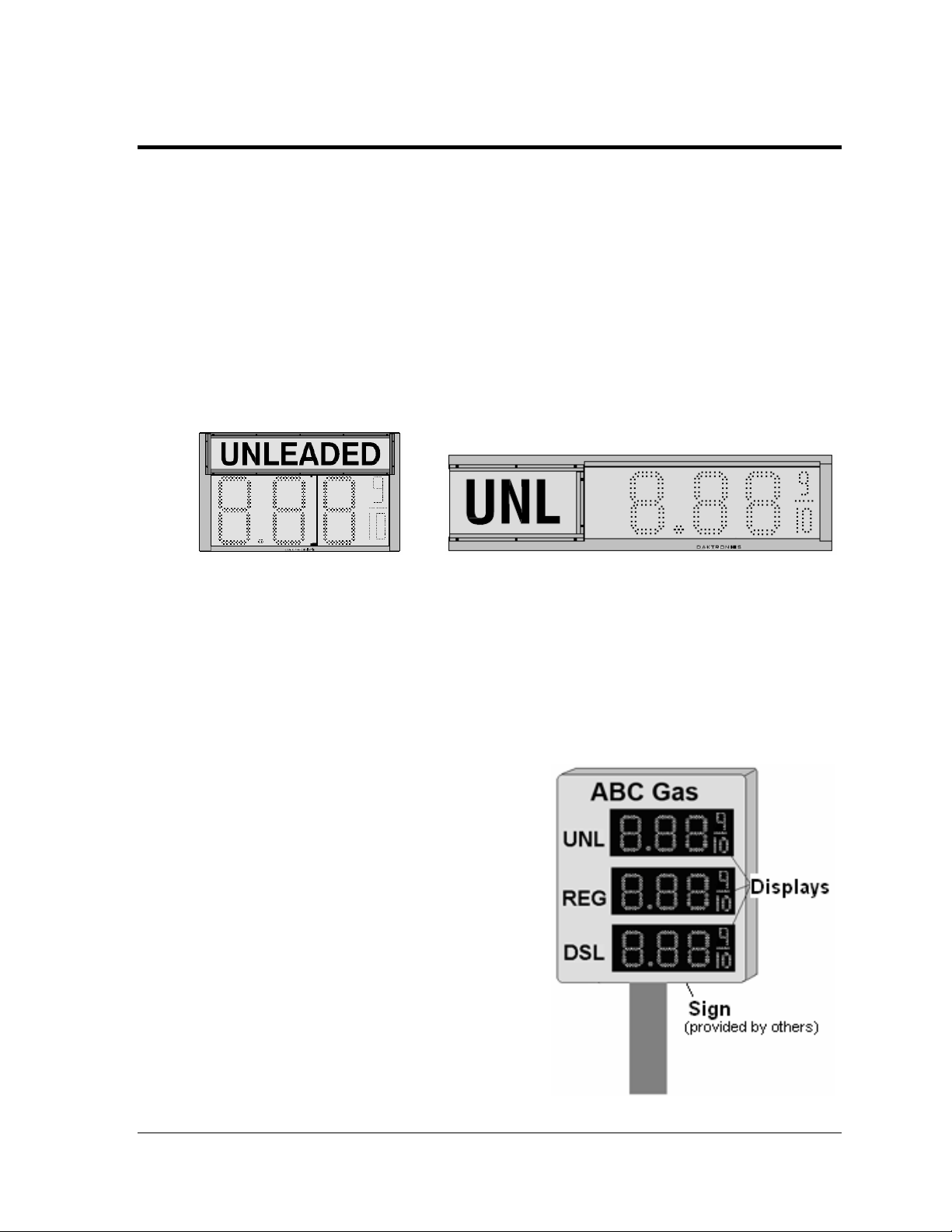
caption either above the digits or to the left of the digits, as shown in Figure 1.
Figure 1: DF-2100 with Top Caption DF-2100 with Side Caption
DataMaster displays use light-emitting diodes (LEDs) to illuminate their numeric digits.
LEDs are high-intensity, low-energy lighting units that use a semiconductor to transform
electrical current into light. All DataMaster displays may be configured with red, amber, or
green LEDs. Because of their LED technology, the displays consume little power, some
barely more than a household lamp.
The DataMaster outdoor LED displays have been designed for use with a DataMaster
hand-held controller, a radio controlled RC-100 system, or the RC-50 mini remote control.
In this manual, the complete structure will be
referred to as a "sign." Each sign typically
consists of a number of digit displays. Refer to
Figure 2.
Figure 2: Sign with Digit Displays
™
100
Introduction 1
Page 10
Model Number
The DataMaster model number for these displays is described as follows:
DF-
2100 =
HH =
C =
X# =
SF =
Outdoor digit display with backlit ID panel
Digit height in inches
LED Color- R (Red), A (Amber), or G (Green)
Illuminated product ID, options:
L# - Left product panel,
# indicates nominal cabinet width (ft)
T# - Top product panel,
# indicates nominal cabinet width (ft)
SF – Single Face, one cabinet
DF-2100-HH-C-X#-SF
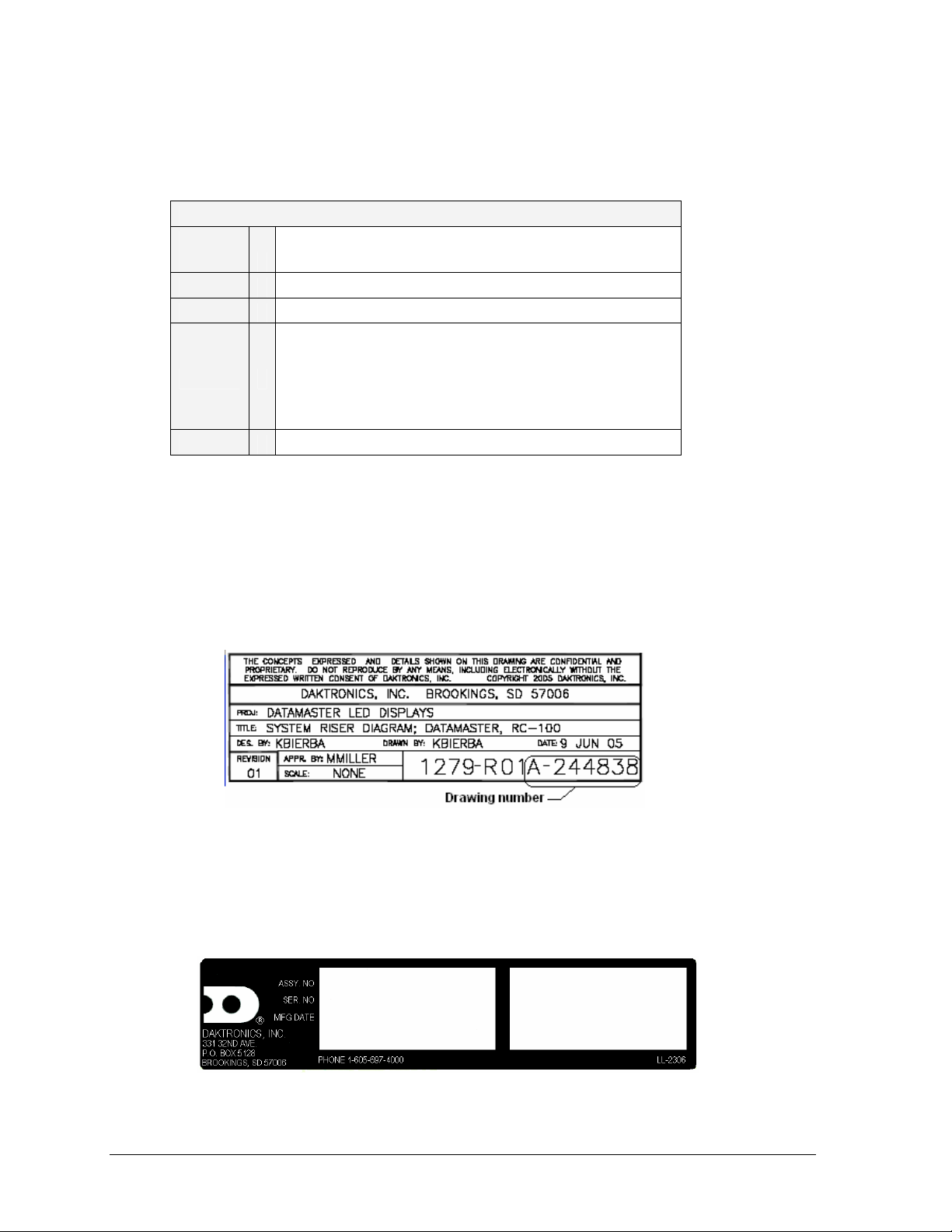
1.2 Drawing and Label Information
Drawings are sometimes referenced at the beginning of a section. Daktronics identifies
drawings with a number which is located in the bottom right corner of each drawing (Figure
3). This reference number includes the last set of digits and the letter preceding them. The
drawing in this example would be referred to as Drawing A-244838.
Figure 3: Daktronics Drawing Label
The serial and model numbers of a Daktronics display can be found on the ID label inside the
display. The label will be similar to the one shown in Figure 4. When calling Daktronics
Customer Service, please have this information available to ensure that your request is
serviced as quickly as possible. For future reference, note the display model number, serial
number, and installation date inside the front page of this manual.
Figure 4: Display Identification Label
2 Introduction
Page 11
Section 2: Mechanical Installation
Important Safeguards
• Read and understand these instructions before installing the display.
• Do not drop the controller or allow it to get wet.
• Properly ground the display with a ground rod at the sign location.
• Disconnect power when servicing the display.
• Do not modify the display structure or attach any panels or coverings without the written
consent of Daktronics, Inc.
2.1 Shop Drawings
The table below gives the shop drawing number for each display model. All drawings are
inserted into Appendix A.
Single-faced displays with left side captions
Drawing Title/Display Type Drawing Number
Shop Drawing, DF-2100-10-L5-SF Drawing B-304066
Shop Drawing, DF-2100-13-L6-SF Drawing B-304229
Shop Drawing, DF-2100-18-L8-SF Drawing B-304719
Shop Drawing, DF-2100-24-L10-SF Drawing B-304808
Single-faced displays with top captions
Drawing Title/Display Type Drawing Number
Shop Drawing, DF-2100-10-T3-SF Drawing B-303105
Shop Drawing, DF-2100-13-T3.5-SF Drawing B-303309
Shop Drawing, DF-2100-18-T5.5-SF Drawing B-303675
Shop Drawing, DF-2100-24-T6-SF Drawing B-303900
Shop Drawing, DF-2100-24-T8-SF Drawing B-303983
Shop Drawing, DF-2100-36-T8-SF Drawing B-269576
Shop Drawing, DF-2100-48-T11-SF Drawing A-236905
Shop Drawing, DF-2100-60-T14-SF Drawing A-232509
Mechanical Installation 3
Page 12

2.2 Specifications
DataMaster Petroleum Price Double-Faced Displays with Left Caption
Model Dimensions Weight Digit Size
DF-2100-10-R-L5-SF
DF-2100-10-A-L5-SF
DF-2100-10-G-L5-SF
DF-2100-13-R- L6- SF
DF-2100-13-A-L6- SF
DF-2100-13-G- L6- SF
DF-2100-18-R- L8- SF
DF-2100-18-A-L8- SF
DF-2100-18-G- L8- SF
DF-2100-24-R- L10- SF
DF-2100-24-A-L10- SF
DF-2100-24-G- L10- SF
DF-2100-10-R-T3-SF
DF-2100-10-A-T3-SF
DF-2100-10-G-T3-SF
DF-2100-13-R-T3.5-SF
DF-2100-13-A-T3.5-SF
DF-2100-13-G-T3.5-SF
DF-2100-18-R-T5-SF
DF-2100-18-A-T5- SF
DF-2100-18-G-T5- SF
DF-2100-24-R-T6- SF
DF-2100-24-A-T6- SF
DF-2100-24-G-T6- SF
DF-2100-36-R-T10-SF
DF-2100-36-A-T10-SF
DF-2100-36-G-T10-SF
DF-2100-48-R-T11-SF
DF-2100-48-A-T11-SF
DF-2100-48-G-T11-SF
DF-2100-60-R-T14-SF
DF-2100-60-A-T14-SF
DF-2100-60-G-T14-SF
H1’-3”, W5’-0”, D0’-6”
(381 x 1524 x 152 mm)
H1’-6", W6’-0", D0’-6"
(457x 1829 x 152 mm)
H2’-0", W8’-0", D0’-6"
(610 x 2438 x 152 mm)
H2’-6", W10’-0", D0’-6"
(762 x 3048 x 152 mm)
H1’-9", W3’-0", D0’-6"
(533 x 914 x 152 mm)
H2’-2", W3’-6", D0’-6"
(660 x 1067 x 152 mm)
H3’-0", W5’-0", D0’-6"
(914 x 1524 x 152 mm)
H4’-0", W6’-0", D0’-6"
(1219 x1829 x152 mm)
H5’-6", W8’-0", D0’-8"
(1676 x 2438 x 203 mm)
H7’-0", W11’-0", D0’-8"
(2134 x 3353 x 203 mm)
H9’-0", W14’-0", D0’-8"
(2743 x 4267 x 203 mm)
50 lb
(23 kg)
60 lb
(27 kg)
70 lb
(32kg)
80 lb
(36 kg)
45 lb
(20 kg)
55 lb
(25 kg)
100 lb
(45 kg)
110 lb
(50 kg)
190 lb
(86 kg)
350 lb
(159 kg)
600 lb
(272 kg)
10”
(254 mm)
13"
(330 mm)
18"
(457 mm)
24"
(610 mm)
10"
(254 mm)
13"
(330 mm)
18"
(457 mm)
24"
(610 mm)
36"
(914 mm)
48"
(1219 mm)
60"
(1524 mm)
Maximum
Power
120 W 120 VAC
135 W
275 W =
Red, Amber
350 W =Green
275 W =
Red, Amber
350 W =Green
135 W 120 V AC
150 W 120 V AC
275 W =
Red, Amber
350 W =Green
275 W =
Red, Amber
350 W =Green
1300 W 120 V AC
1336 W 120 V AC
1636 W 120 V AC
Circuit
15 A
120 VAC
15 A
120 VAC
15 A
120 VAC
15 A
15 A
15 A
120 V AC
15 A
120 V AC
15 A
15 A
15 A
15 A
4 Mechanical Installation
Page 13
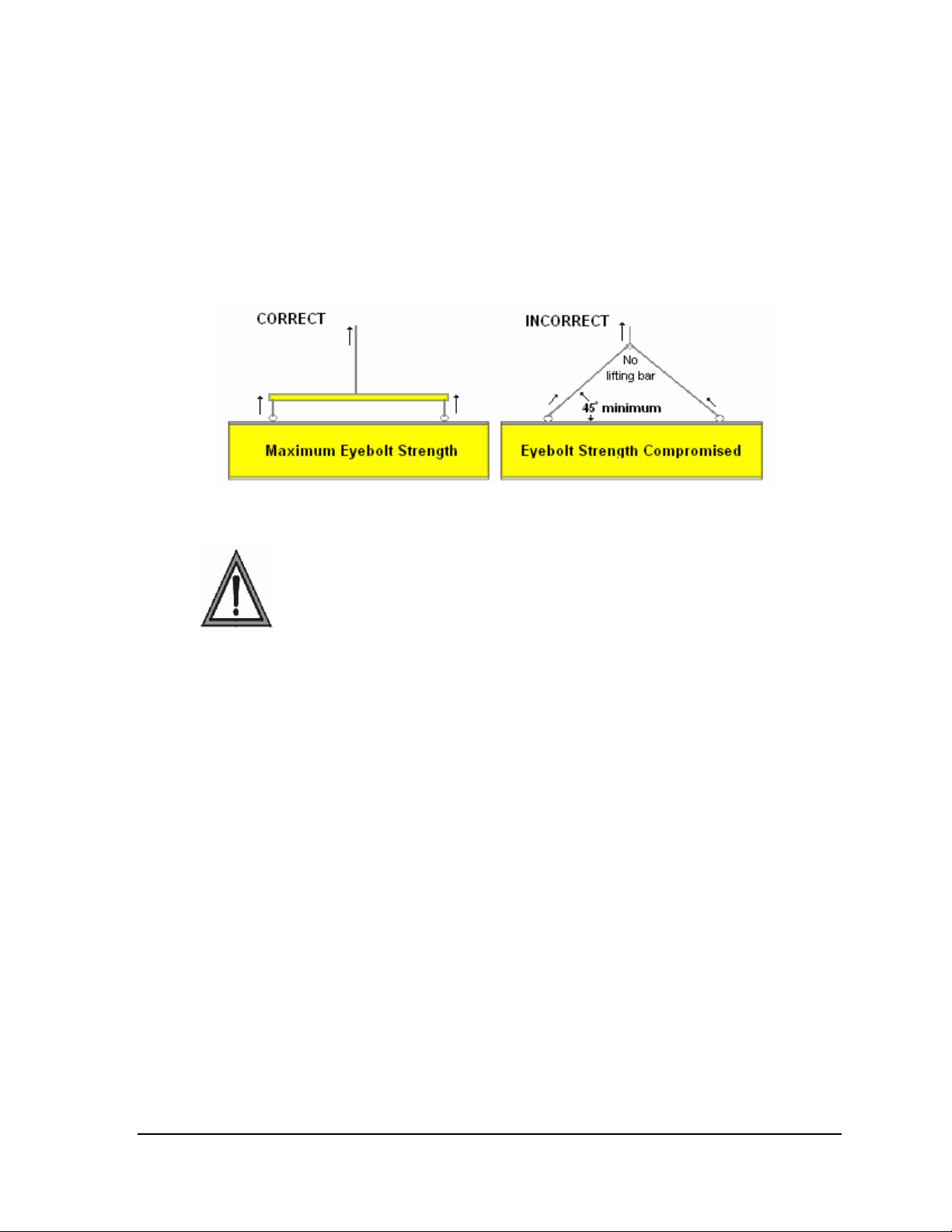
2.3 Lifting the Displays
While DataMaster outdoor digit displays are designed for pole mounting, every installation
will be different. Actual site demands will dictate the appropriate mounting method.
Daktronics strongly recommends using a spreader or lifting bar to lift the display. Using a
spreader bar ensures that the force on the eyebolts is straight up, minimizing lifting stress.
Figure 5 illustrates the correct and incorrect lifting methods.
Figure 5: Lifting the Display
Note: Daktronics assumes no liability for display damage or injury resulting from
incorrect setup or incorrect lifting methods.
Eyebolts are intended for lifting during installation only. Do not attempt to
permanently support the display by the eyebolts.
Eyebolts may be removed once the display is in place. The bolt sizes and threads vary based
on the size and weight of the display. Common bolts used are 1/4"-20, 3/8"-16, 1/2"-13, and
5/8"-11.
RC-100 Controller 5
Page 14

Page 15
Section 3: Electrical Installation
Reference Drawing:
Specifications; Gas Price Driver, 4 Col........................................................... Drawing A-250728
Wiring Schematic, DF-2000/4000 Series........................................................ Drawing A-263988
Address Dip Switch Settings........................................................................... Drawing B-256001
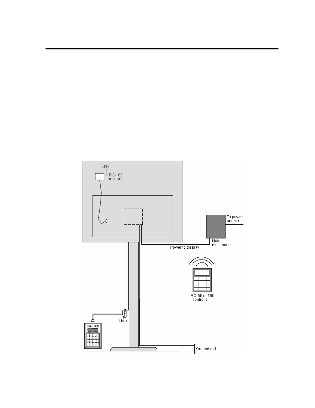
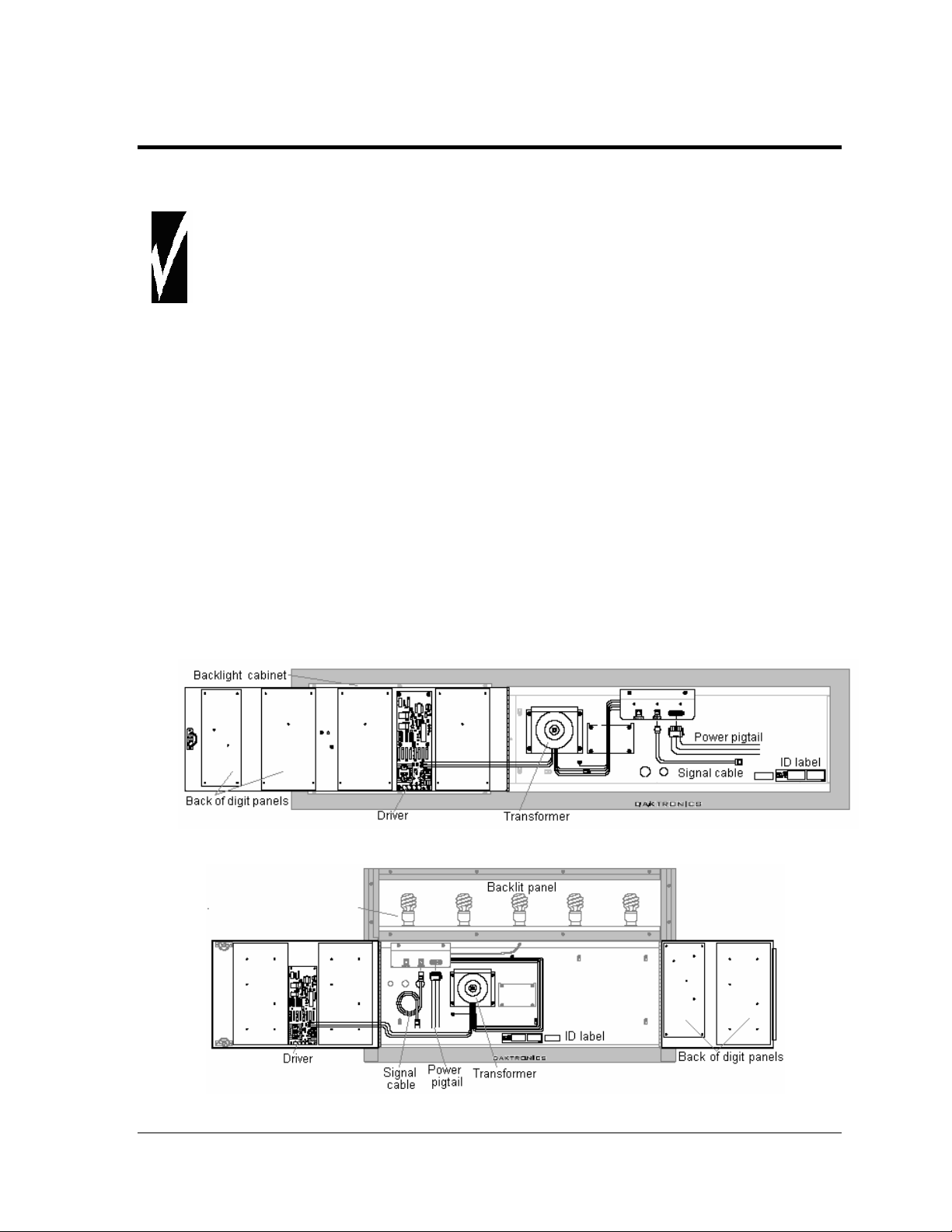
Electrical installation consists of the following processes, as illustrated in Figure 6:
• providing power and ground to a disconnect near the display.
• routing power and ground from the main disconnect to the display driver/power enclosure.
• connecting the display ground to a ground rod at the sign location.
• routing the control signal cable from the control location to the sign location. Signal options
include the DM-100, RC-100, and RC-50.
Each of these steps is covered in the following section.
Figure 6: Power and Signal Routing
Electrical Installation 7
Page 16

3.1 Power Installation
Only qualified individuals should perform power termination to the display.
It is the responsibility of the electrical contractor to ensure that all electrical
work meets or exceeds local and national codes.
Daktronics DataMaster displays have been designed for simple hook-up of power and
signal. Correct power installation is imperative for proper display operation. Improper
installation could result in serious damage to the equipment and could be hazardous to
personnel.
The DataMaster outdoor displays require a dedicated, 120 V circuit for incoming power. The
display itself has no breakers or fuses. Refer to Drawing A-263988 and to the chart in Section
2 to determine maximum power requirements for this model.
It is critical that the display circuit be fused at 15 A, and that all conductors used must
be designed to pass a 15 A current in normal operation. Failure to meet wiring and
over-current protection device requirements is a violation of the National Electrical
®
Code
and will void the display warranty.
Grounding
Displays MUST be grounded according to the provisions outlined in Article 250 of
the National Electrical Code and according to the specifications in this manual.
The display system must be connected to an earth electrode installed at the display. Proper
grounding is necessary for reliable equipment operation. It also protects the equipment from
damaging electrical disturbances and lightning. The display must be properly grounded or
the warranty will be void. Refer to Schematic Drawing A-263988.
Important points about grounding:
• Follow local and national codes: The material of an earth-ground electrode differs from
region to region and from conditions present at the site. Consult the National Electrical Code
and any local electrical codes that may apply.
• Support structure cannot be used as an earth-ground electrode: The support is generally
embedded in concrete. If embedded in earth, the steel is either primed or it corrodes, making
it a poor ground.
• One grounding electrode for each display face: The grounding electrode is typically one
grounding rod for each display face. Other grounding electrodes as described in Article 250
of the National Electric Code may be used.
• Resistance to ground 10 ohms or less: This is required by Daktronics for proper display
performance. If the resistance to ground is higher than 10 ohms, it will be necessary to install
additional grounding electrodes to reduce the resistance. The grounding electrode should be
installed within 25 feet of the base of the display. The grounding electrode must be connected
to the ground wire inside the display.
8 Electrical Installation
Page 17
Power Disconnect
The National Electrical Code requires the use of a lockable power disconnect within sight of
or at the display. Follow these guidelines for correct connection:
• Connect the grounding electrode cable at the local disconnect, never at the display
driver/power enclosure.
• Use a disconnect that opens all of the ungrounded phase conductors.
In order for this device to provide protection, the power must be disconnected when the
display is not in use. The controller should also be disconnected from power and from the
signal j-box when the system is not being used. The same surges that may damage the
display's driver can also damage the controller's circuit.
Power Installation
For this type of installation, the power circuit must contain an isolated earth-ground
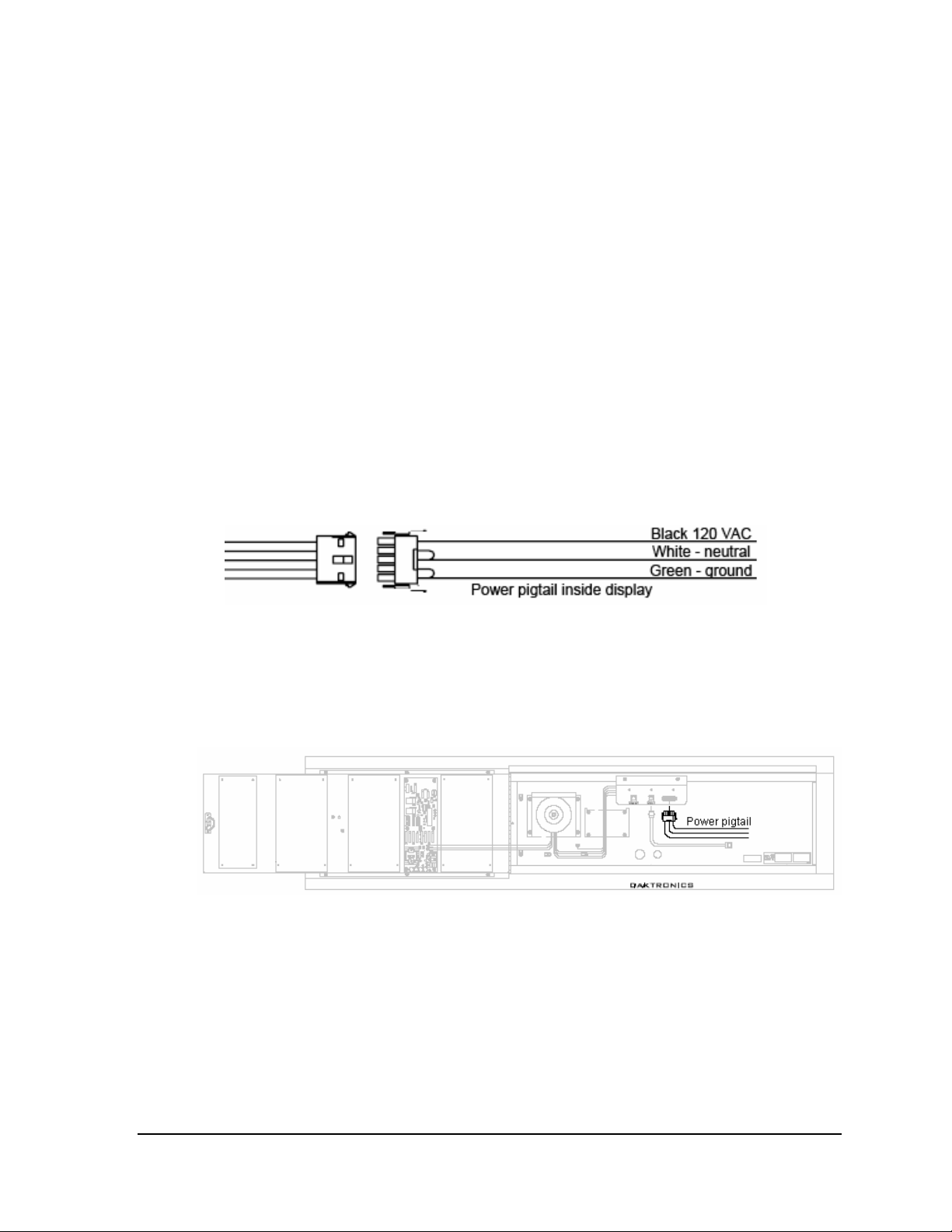
conductor. Power connects to the pigtail inside the display (Figure 7). The pigtail has three
wires: black (120 V AC line), white (neutral) and green (ground), and a 5-pin plug on one
end. The plug is connected to the mating plug on the transformer. Use wire nuts to connect
power wires to the pigtails.
Figure 7: Power Connection
To access the power pigtail inside the display, open the latch access fasteners on the digit
panels. Smaller models have a single door that opens from the right. Larger models have two
doors that open near the center. Use a screwdriver to turn the fasteners a half-turn
counterclockwise to open the panel. Remove two wing nuts to open the left panel, if present.
Figure 8: Example of Power Pigtail Location
Electrical Installation 9
Page 18
3.2 Signal Connection
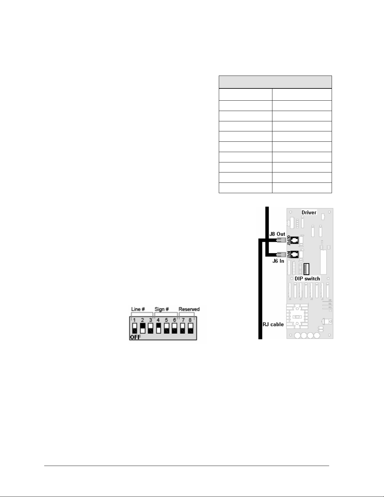
LED Drivers
In the display, the LED driver performs the task of
switching digits on and off. One driver at each sign
installation is designated as the “host driver.” This
driver receives its signal directly from the controller
on the Signal In connector J6. The Signal Out
connector J8 is used to connect to “client drivers,”
the drivers in other displays in this network.
Other communication types are initially connected
as shown in the chart: J11 (Radio, RC-100 system)
and J12 (RC-50 receiver). These initial connections
are then routed to the J6 Input jack. Refer to
Drawings A-250728 for a complete listing of driver
connector functions and wiring pin numbers.
4-Column LED Driver
Connector No. Function
J1 – 4 Digits
J5 Not loaded
J6 CL Input
J7 Program
J8 CL Output
J9 Not loaded
J10 Modem
J11 Radio
J12 RC-50 Input
Signal Wiring
Signal wires are terminated with a telephone-type RJ14
connector. Route the cable from the jack in the j-box to J6 on the
host driver (Figure 9). Run another RJ14 connector from J8
(Output) to the next (client) display, connecting at J6 (Input).
Follow this sequence to all displays in the sign network.
Address Dip Switch Settings
Every driver, either host or client, must have a unique address.
The address is set by moving the individual toggle switches in
the eight-position dip switch case located on the driver (Figure
10). The dark area shows that the switch has been pushed down.
In the example, switches 2 and 4 are on.
Figure 10: Dip Switches
Figure 9: Driver
Addresses allow the user to set both line number (switches 1-3) and sign number (switches 4-
6) in as many as eight sign groups. All displays with the same line number will show the
same price.
Refer to Drawing B-256001 for an illustration of the client/host driver setups and for a chart
showing line number and sign number settings.
10 Electrical Installation
Page 19
3.3 Power Up Self-test
Every time the display is powered up, it will run through a verification sequence. This is a
good way to check that the displays are set up and working correctly. The following items
will be shown on the digit displays. The second column explains the significance of each
item.
Information shown
on display
Meaning of information
rNN
XLY
Revision number of software
X = sign #; L is constant, Y = line #
Electrical Installation 11
Page 20

Page 21
Section 4: Diagnostics and Troubleshooting
Important Notes
Disconnect power before doing any repair or maintenance work on the display.
Allow only qualified service personnel access to internal display electronics.
Disconnect power when not using the display.
Daktronics displays are built for long life and require little maintenance. However, at times, displays
may not work correctly. Use this section to define the problems and find solutions.
4.1 Component Location and Access
To access the components of these displays, open the latch access fasteners on the digit
panels. Some models have one door that opens from the right. Other models have two doors
that open near the center. Use a screwdriver to turn the fasteners a half-turn
counterclockwise to open the panel. Remove two wing nuts to open the left panel, if present.
The internal components of the display are located as shown in Figure 11 and Figure 12. The
driver is typically mounted between two digit boards. The power pigtail will be connected to
the power source wiring with wire nuts.
Note: Disconnect power before servicing the display. Disconnect power, also, when the
display is not in use.
Figure 11: Inside View of Left Panel, Single-door Display
Figure 12: Inside View of Top Panel, Two-door Display
Diagnostics and Troubleshooting 13
Page 22

4.2 Diagnostics
Driver LEDs
The driver inside the display contains three LEDs that provide information
about the working of the display. Refer to Figure 13 for their location. These
LEDs can help pinpoint problems with driver set-up or operation.
The LEDs give the following information:
LED Color Status
DS1 Green Continuous light when driver has power.
DS2 Red Blinks when driver receives signal.
DS3 Amber Blinks when driver is running.
Power On Self-Test
A useful troubleshooting tool is the power on self-test performed by the host
driver every time the display powers up: The display should show the
information listed in the left column. Every “X” in the chart refers to a
number.
Information shown
on display
rNN
XLY
Meaning of information
Revision number of software
X = sign #; L is constant, Y = line #
Figure 13: Driver
Diagnostics
14 Diagnostics and Troubleshooting
Page 23

4.3 Troubleshooting
This section lists potential problems with the display, indicates possible causes, and suggests
corrective action. This list does not include every possible problem, but it does represent
some of the more common situations that may occur. (Refer to the appropriate manual for a
list of potential problems with add-on or separately mounted message centers.
Symptom/
Condition
Possible Cause Solution
No displays in the
sign will light
Multiple line sign
with all lines
showing same
prices
Digit will not light • Black wire to digit broken.
Segment or several
LEDs will not light
Segment or digit
stays lit
• Power incorrectly set up.
• Addresses not set correctly.
• Addresses not set
correctly.
• Poor contact at driver
connection.
• Driver malfunction.
• Broken LEDs.
• Driver failure.
• Broken wire between
driver and digit.
• Poor contact at driver
connector.
• Driver failure.
• Short circuit on digit.
• Open display with host driver
and check Power LED
(Section 4.2).
• Check each driver to verify
correct address settings
(Section 3.2).
• Set up different address for
each line of sign (Section 3.2).
• Replace harness.
• Clean contacts.
• Replace driver.
• Replace segment or digit.
• Replace driver.
• Replace harness.
• Clean contact or replace
harness.
• Replace driver.
• Replace harness.
Data appears in the
wrong place on the
sign
Data appears on the
wrong line of the
display
Display shows "E4". • No Message Error: This
• Signal connections are
not correct.
• Incorrect address settings
on drivers.
code is shown when no
messages are
downloaded to the
display.
• Reconnect signal wiring to
drivers (Section 3.2).
• Change addresses on drivers
(Section 3.2).
• Download a new message to
the display using the [Update
Display] key on the
DataMaster 100 controller.
Diagnostics and Troubleshooting 15
Page 24

Page 25

Section 5: Parts Replacement
Daktronics Petroleum Price Displays are built for long life and easy maintenance. On occasion,
however, a part may need to be replaced. In that case, follow these steps.
1. Find the part number label on a part or refer to the list in Section 5.1 for the correct part
number.
2. Read Section 5.3, Daktronics Exchange and Repair & Return Programs, for step-by-step
instructions on obtaining a new part.
3. When the part is received, follow the instructions in this section for replacing it.
5.1 Replacement Parts List
Description
Daktronics Part
No.
Driver & Internal Components for Digits 24" & smaller
Toroid Transformer, Display T-1124
Digit cable, 1 ft. W-1575
Digit cable, 3 ft. W-1576
Digit cable, 4 ft. W-1577
Digit cable, 6 ft. W-1578
Digit cable, 8 ft. W-1579
Gas Price Driver, 4-col 0P-1356-0002
Signal Surge Card 0P-1356-0001
Decimal / Driver, red 0P-1192-0353
Decimal / Driver, amber 0P-1192-0355
Decimal / Driver, green 0P-1192-0354
Driver & Internal Components for Digits 36" & larger
Driver, 4-column MASC, LED 0P-1192-0068
Light sensor 0A-1279-0203
Protocol plug (Protocol 4) 0A-1279-0089
Power supply, 24 V DC, 1 KW A-1856R
Transformer, Pri. 115V; Sec. 10 VCT @1.2A T-1072
Address #1 Plug 0A-1150-0122
8-Segment breakout board 0P-1192-0326
Communication Boards and Accessories
Signal surge suppression board 0P-1110-0011
Modem, RS232 coated, internal, 0P-1279-0003
J-box, signal converter, w/modem 0A-1279-0162
J-box, signal converter, radio 0A-1279-0161
RJ11 to RJ45, M-M, straight, 18” cable 0A-1137-0300
Server Radio, outdoor 0A-1146-0079
Client Radio, w/Quick Connect 0A-1146-0078
Cable, 6-cond., 18 AWG, j-box to Server Radio W-1370
Junction box, outdoor, 9-pin D-male 0A-1196-0093
Junction box, indoor, 9-pin D, male 0A-1196-0099
DM-100 Controller 17
Page 26

Description
RC-50 Radio with overlay 0A-1356-0064
Receiver card 0P-1192-0355
Antenna A-2015
Transformer, wall pack T-1118
RC-100 Price Display insert LL-2617
RC-100 hand held assembly 0A-1110-0046
RC-100 receiver 0A-1110-0045
DM-100 hand-held controller 0A-1196-0088
DM-100 outdoor wired installation kit 0A-1356-0002
DM-100 indoor wired installation kit 0A-1356-0105
Cable, serial, DB9 male to DB9 female W-1267
DM100 Insert Time & Temp/Petroleum Price 0G-164998
Daktronics Part
No.
Digits and Accessories 24” and smaller
10” Digit 7-segment, Red 0P-1192-0356
10” Digit, 7-segment, Amber 0P-1192-0359
10” Digit, 7-segment, Green 0P-1192-0357
13” Digit, 7-segment, Red, 0P-1192-0347
13” Digit, 7-segment, Amber 0P-1192-0348
13” Digit, 7-segment, Green 0P-1192-0349
18” Digit, 7-segment, Red 0P-1192-0341
18” Digit, 7-segment, Amber 0P-1192-0342
18” Digit, 7-segment, Green 0P-1192-0343
22”, Digit segment, Red, Horizontal 0P-1192-0293
22”, Digit segment Amber, Horizontal 0P-1192-0297
22”, Digit segment, Green, Horizontal 0P-1192-0295
24”, Digit segment, Red, Vertical 0P-1192-0372
24”, Digit segment, Amber, Vertical 0P-1192-0374
24”, Digit segment, Green, Vertical 0P-1192-0373
7” 9/10 Red, 14 pin, 24 V 0P-1192-0350
7” 9/10 digit, Amber, 14 pin, 24 V 0P-1192-0351
7” 9/10 digit, Green, 14 pin, 24 V 0P-1192-0352
13”, 9/10 digit, Red, 14 pin, single stroke 0P-1192-0378
13”, 9/10 digit, Amber, 14 pin, single stroke 0P-1192-0379
13”, 9/10 digit, Green, 14 pin, single stroke 0P-1192-0380
13”, 9/10 digit, Red, 14 pin, double stroke 0P-1192-0344
13”, 9/10 digit, Amber, 14 pin, double stroke 0P-1192-0345
13”, 9/10 digit, Green, 14 pin, double stroke 0P-1192-0346
Digits and Accessories 36” and larger
Speed nut, M3 Kingnut black nylon, Push nut HS-1453
Spacer, washer with steel backing HC-1221
Indicator, 4" Red, pc board 0P-1192-0244
Indicator, 4" Amber, pc board 0P-1192-0245
Indicator, 4" Green, pc board 0P-1192-0248
36" Digit segment, Red, Vertical 0P-1192-0208
36” Digit segment, Red Horizontal 0P-1192-0209
36" Digit segment, Amber, Vertical 0P-1192-0222
18 DM-100 Controller
Page 27

Description
36” Digit segment, Amber Horizontal 0P-1192-0223
36” Digit segment, Green, Vertical 0P-1192-0333
36” Digit segment, Green Horizontal 0P-1192-0334
48” Digit segment, Red, Vertical 0P-1192-0212
48” Digit segment, Red Horizontal 0P-1192-0213
48" Digit segment, Amber, Vertical 0P-1192-0226
48" Digit segment, Amber Horizontal 0P-1192-0227
48" Digit segment, Green, Vertical 0P-1192-0337
48" Digit segment, Green, Horizontal 0P-1192-0338
60" 1/2 segment, Red, Vertical 0P-1192-0281
60" 1/2 segment, Red Horizontal 0P-1192-0280
60" 1/2 segment, Amber, Vertical 0P-1192-0283
60" 1/2 segment, Amber Horizontal 0P-1192-0282
60" 1/2 segment, Green, Vertical 0P-1192-0323
60" 1/2 segment, Green, Horizontal 0P-1192-0321
24" 9/10 Red, pc board 0P-1192-0232
24" 9/10 Amber, pc board 0P-1192-0233
24" 9/10 Green, pc board 0P-1192-0325
24” 9/10 Red, w/faceplate 0A-1192-2359
24” 9/10 Amber, w/faceplate 0A-1192-2360
24” 9/10 Green, w/faceplate 0A-1192-3082
Daktronics Part
No.
Additional Replacement Parts
Lamp, 15 W spiral compact fluor. DS-1563
Lamp, 30” T12 fluorescent DS-1034
Lamp, 36” T12 fluorescent DS-1521
Lamp, 42” T12 fluorescent DS-1501
Lamp, 48” T12 fluorescent DS-1036
Lamp, 60” T12 fluorescent DS-1049
Lamp, 72” T12 fluorescent DS-1037
Lamp, 84” T12 fluorescent DS-1038
Lamp, 96” T12 fluorescent DS-1048
Lamps 5’4” DS-1053
Lamps 10’ DS-1213
Ballast, 1.65 A fluorescent A-1368
Ballast, 2.5 A fluorescent A-1369
Ballast, 2.8 A fluorescent A-1370
Ballast 4, 5, 6 lamps (24-48 feet) A-1371
DM-100 Controller 19
Page 28

5.2 Instructions for Replacing Parts
Replacing a Digit Panel
The digit circuit board is the platform for the LEDs and is mounted to the back of the digit
panel. Refer to Figure 14. If some LEDs are not working, do not attempt to remove an
individual LED. Replace the entire digit panel.
To remove a display digit panel, follow these steps:
1. Open the digit panel as described in Section 4.1.
2. Disconnect the power/signal connector from the
back of the digit. Release the connector by
squeezing together the locking tabs as the plug is
pulled free.
3. The digits are secured to the inside of the panel
with fixed machine screws, spacers, and push nuts.
Remove the nuts and lift the digit off the standoff
screws. The push nuts can be removed in several
ways, but Daktronics recommends using a 9/32"
nut driver.
4. Move the new digit into place and install the
pushnuts.
5. Reconnect the power/signal connector plug. Note:
This is a keyed connector and will attach in one way
only. Do not attempt to force the connection!
6. Replace the back panel of the display, latching it
securely.
Figure 14: Digit Assembly
Replacing a Digit Segment
Large digits are constructed in segments, as shown in Figure 15. In this case, it may be
possible to replace only the defective segment. As with smaller digits, the segment circuit
boards are mounted to the back of the digit panel. Do not attempt to remove individual
LEDs. Replace a malfunctioning colon, decimal, or indicator assembly in the same manner.
To remove a digit segment, follow these steps:
1. Open the digit panel as described in Section 4.1.
2. Disconnect the 2-pin power/signal connector from the back
of the individual segment. Release the connector by
squeezing together the locking tabs as the connector is pulled
free.
3. The individual segments are secured to the inside of the
panel with fixed machine screws, spacers, and push nuts.
Remove the nuts and lift the segment off the standoff screws.
4. Position a new segment over the screws and tighten the nuts.
5. Reconnect the power/signal connector. Note: This is a keyed
connector it will attach in one way only. Do not attempt to
force the connection!
6. Close and secure the digit panel and test the display.
20 DM-100 Controller
Figure 15: Digit Segments
Page 29

Replacing a Driver
The driver is mounted to the front panel between digit boards.
The back panel will need to be removed to replace the driver.
To replace a driver, follow these steps:
1. Open the display as described in Section 4.2.
2. Disconnect and label all connectors from the driver.
Release each connector by squeezing together the locking
tabs and pulling on the plug.
3. Remove the screws and nuts securing the driver to the
inside of the enclosure.
4. Carefully lift the driver from the display.
5. Move the new driver into place and fasten securely.
6. Reconnect all the connectors. Note: Remember that these
are keyed connectors and will attach in one way only. Do
not attempt to force the connections.
7. Replace the back panel and securely fasten the latches.
8. Test the display to make sure that it is working correctly.
Figure 16: Driver
5.3 Daktronics Exchange and Repair & Return Programs
To serve customers’ repair and maintenance needs, Daktronics offers both an Exchange
Program and a Repair & Return Program.
Before Contacting Daktronics
Fill in this chart before calling Customer Service:
Display Serial No. ___________________________________
Display Model No. __________________________________
Date Installed ______________________________________
DataMaster Serial No. _______________________________
Exchange Program
Daktronics unique Exchange Program is a quick service for replacing key parts in need of
repair. If a part requires repair or replacement, Daktronics sends the customer a replacement,
and the customer sends the defective part to Daktronics. This decreases display downtime.
To participate in the Exchange Program, follow these steps,
1. Call Daktronics Customer Service: 866-343-3122
DM-100 Controller 21
Page 30

2. When the new exchange part is received, mail the old part to Daktronics.
If the replacement part fixes the problem, send in the problem part which is being
replaced.
a. Package the old part in the same shipping materials in which the replacement
part arrived.
b. Fill out and attach the enclosed UPS shipping document.
c. Ship the part to Daktronics.
3. A charge will be made for the replacement part immediately, unless a qualifying
service agreement is in place.
In most circumstances, the replacement part will be invoiced at the time it is shipped.
4. If the replacement part does not solve the problem, return the part within 30
working days or the full purchase price will be charged.
If the equipment is still defective after the exchange was made, please contact
Customer Service immediately. Daktronics expects immediate return of an exchange
part if it does not solve the problem. The company also reserves the right to refuse
parts that have been damaged due to acts of nature or causes other than normal wear
and tear.
Repair & Return Program
For items not subject to exchange, Daktronics offers a Repair & Return Program. To send a
part for repair, follow these steps:
1. Call or fax Daktronics Customer Service:
Phone: 866-343-3122 Fax: 605-697-4444
2. Receive a Return Materials Authorization (RMA) number before shipping.
This expedites repair of the part.
3. Package and pad the item carefully to prevent damage during shipment.
Electronic components, such as printed circuit boards, should be placed in an
antistatic bag before boxing. Daktronics does not recommend Styrofoam peanuts in
packaging.
4. Enclose:
your name
address
phone number
the RMA number
a clear description of symptoms
Shipping Address
Daktronics Customer Service
PO Box 5128
331 32nd Avenue
Brookings, SD 57006
22 DM-100 Controller
Page 31

Section 6: DM-100 Controller
This section describes the set up and operation of the DataMaster 100 (DM-100) Controller. The DM100 may be used with either an indoor or outdoor j-box, both of which are explained in this section.
Note also the information on the DataMaster Insert.
Reference Drawing:
Address Dip Switch Settings........................................................................... Drawing B-256001
Insert, LL-2551 Price/T&T Display.................................................................. Drawing A-167856
6.1 DM-100 Overview
The DataMaster 100 Series controller, shown in Figure 9, is a
hand-held controller designed to operate Daktronics LED
DataMaster
ABS plastic, making it a durable and convenient control
option. The console’s liquid crystal display (LCD) guides the
user through the operation of the system.
The DM-100 can be configured to display petroleum price,
motel rates, and time and temperature data. Refer to
Drawing B-256001 for information on possible control
options and connection procedures.
Note: When the carrier delivers this Daktronics order, open
displays. This lightweight controller is encased in
the packages and inspect for shipping damage such as
rattles and dents. See that all equipment is included as
shown on the packing slip. If deficiencies are found,
immediately report them to Daktronics. Save all
packing materials in case warranty repair or exchange
is needed.
Figure 17: DataMaster (DM) 100
Replacement Parts List
The following is a list of possible replacement parts for the DM-100 controller. When reordering a part, be sure to use its corresponding part number. To obtain a part from
Daktronics, refer to Section 5.3 for instructions.
DM-100 Controller 23
Description Daktronics Part No.
Wall pack transformer T-1118
DM-100 controller
Control Insert LL-2551
Cable, DB-9 male to DB-9 female, 10' W-1267
0A-1196-0088
Page 32

6.2 Connecting the DM-100 to the Display
The DataMaster displays may be controlled from a location inside a building or from the
base of the display, depending on customer preference. Drawing B-256001 and the
subsections that follow provide greater detail on both installations using signal wire.
Wire Control from the Base of the Sign
This outdoor control option (Figure 18) permits operation of the
sign from the base of the display. The controller is connected to
an outdoor junction box mounted on the display pole, which
routes the signal to the sign through one 2-pair cable, 22 AWG.
Cable is in conduit where required.
This control option does not require the controller to be
connected to a power outlet. In this configuration, the DM-100
uses the sign as a power source.
To operate the display using this setup, connect the 9-pin to 9pin cable from the DM-100 controller to the 9-pin j-box mounted
on the display pole.
Figure 18: Wire Control Outdoors
Wire Control from a Building Location
The indoor control option is illustrated in Figure 19.
The handheld controller is connected to an indoor
junction box (j-box), which routes the signal to the
sign through one 2-pair cable, 22 AWG. Cable is in
conduit where required.
To operate the display using this setup, connect the
9-pin to 9-pin cable from the DM-100 controller to the
9-pin j-box, and plug the controller's wall pack
transformer into a 120 VAC outlet.
Figure 19: Wire Control from Building Location
24 DM-100 Controller
Page 33

6.3 DataMaster Insert and Code
The DM-100 uses a keypad insert to program rate
information into Daktronics LED DataMaster Rate
Displays. The DM-100 insert illustrated in Figure 20 is
used to control the displays.
If an insert is lost or damaged, make a copy of the insert
from Drawing A-167856 located in Appendix A. Cut this
to size and slide it into the DM-100 pocket. Use this as a
reference until a replacement is received.
To start the controller and use the insert to program
information into the display driver, read the next section
carefully to fully understand operation instructions.
Figure 20: DM-100 Insert
6.4 Petroleum Price Display Operation
The DM-100 controller can be configured to program petroleum price variances displayed on
the LED DataMaster Petroleum Price sign. The instructions provided in this section discuss
the functions the operator uses to control the Petroleum Price display.
DM-100 Controller 25
Page 34

Petroleum Price Display Startup
To operate the DataMaster Petroleum Price displays, the DM-100 must first be programmed
to the gas price function. Use the [Set Function] key on start-up. Use the following table as a
guide to start-up procedures.
LCD Screen Action
CURRENT
FUNCTION
GAS PRICE
CHANGE
FUNCTION?
PRESS SET
FUNCT
SELECT
FUNCTION
GAS PRICE ↓↑
The DM-100 handheld controller should now be ready for use. The controller will
“remember” the last function setting, so this step should only need to be done with a new
controller, or one that is configured for different displays. To operate the DM-100, press any
of the keys listed in the following gas price sections.
Plug the wall pack transformer into a 120 V AC
power outlet and connect it to the
This display appears briefly.
This message appears next on the screen.
If GAS PRICE was shown on the bottom line of
the LCD during startup, do nothing. The
controller will automatically default to previous
Gas Price settings.
If a function other than GAS PRICE was shown
on the bottom line of the LCD during startup,
press the
LCD prompt is displayed.
Press the arrow up or down keys<↑↓> until the
gas price option is shown. Press the [Enter] key
to accept.
[Set Function] key while the second
DM-100.
26 DM-100 Controller
Page 35

Petroleum Price Controller Operation
The Petroleum Price Controller LCD display will default to showing the current display
settings on power up. The following text will be shown on the LCD.
LCD Screen Action
LINE PRICE
1 ↓ $1.23 9/10
<EDIT> TO
MODIFY
1 ↓ $1.23 9/10
The display will toggle between these two
screens.
Press the up or down arrow keys <
through the current setting for any of the lines
on the display.
Press the [Enter/Edit] key to modify any of the
line settings.
↑↓> to scroll
Modifying Price Line Settings
The gas price can be modified either by pressing the [Edit] key during operation or by using
the [Menu] key (refer to Menu Items chart following this screen). The following keys
identify items to be edited:
L = Current line number to be edited
D.CC = Current dollars and cents value to edit
T = Current tenths of cent value to edit
LCD Screen Action
EDIT LINE L
$D.CC T/10 ↓
DM-100 Controller 27
Press any of the number keys to edit the price
value for this line. Press the down arrow key <
to modify the value of the 1/10-cent data for this
line (read Note following).
Press [Enter] to accept the new value or press
[Clear] to abort the changes.
Note: The flashing asterisk on the LCD shows
the current data being edited.
Many displays do not have a changeable 1/10cent digit. Changing the tenths-cent value from 9
on these digits will make the digit appear
incorrect.
↓>
Page 36

Menu Items
Pressing the [Menu] key accesses the following settings:
Use Menu items 1-5 to edit the price on each line of the display. Lines are typically numbered
top to bottom with 1 being the top of the display. For further details, refer to Modifying
Price Line Settings discussed previously in this section.
For more information about the Modem Settings submenu, refer to ED-13953: DataMaster
Modem Installation Manual. For additional information about the Display Status or the Set
Time submenus, refer to ED-13894: DataTime Radio Installation Manual. This manual
provides complete details on installation and setup for a bi-directional radio system.
Key Setting
1 Price Line 1
2 Price Line 2
3 Price Line 3
4 Price Line 4
5 Price Line 5
6 LED Test?
7 Display Option
8 Modem Settings
9 Display Status
10 Set Time 12HR
Modem Settings
The following items for a modem can be set using the DM-100:
Key Setting
1 Dial Number
2 Dial out prefix
3 Disconnect time
4 Multiple Dial
28 DM-100 Controller
Page 37

Display Status
The Display Status menu item can be used with a bi-directional display setup to get display
status back from the driver. The controller will cycle through various LCD message screens,
illustrated below and on the following page, that show display status. Press [Clear] at any
time to exit the Display Status submenu.
LCD Screen Action
Display status
Get status?
Driver Firmware
version x.x
Current day/time
mm/dd/yy
HH:MM
Last reset time
Mm/dd/yy hh:mm
Current temp
Xx ºf
TEMP SENSOR
OFFSET Xx ºC
Press [Enter] to get the status of the display that is
connected to the DM-100.
The LCD will scroll through the status sent back from
the display. Following is a list of responses:
Firmware Version
This is the firmware version programmed on the host
MASC driver in the display.
Current Day/Time
This is the Day/Time value set in the driver. The time
format used will be 24-hour.
Note: To set the Day/Time, see the "Set Time"
section of your DataTime display system's
operation manual.
Last Reset Time
This time represents the last time the driver was
reset. Note that the time format used will be
24-hour.
Current Temp
This is the temperature read at the display by the
temp sensor. (This value does not include the offset,
if applicable).
Temp Sensor Offset
This is the temp sensor offset value programmed
into the driver.
DM-100 Controller 29
Page 38

Set Time
This allows the time and date to be set with the DM-100.
LCD Screen Action
SET TIME–12HR
HH:MM AM ↓
HH – Current hours value
MM – Current minutes value
AM – Current AM/PM setting (not shown when
24-hour time is selected)
Using the number keys, enter the Time in the
12-hour (or 24-hour) format. Press the down
arrow key <↓> to modify the AM/PM setting.
Note: The flashing asterisk shows the current
data being edited.
To save changes, press the [Enter] key when
finished editing.
Press the [Clear] key to cancel changes.
After setting the time you will need to set the date. If the date is already correct, enter
through the date and press [Enter] to send the time to the display.
LCD Screen Action
DIM level xx
0=dim
Dim Level
• This is the intensity level of the display; 0 is the
63=bright
Dimming mode
Automatic
Dimming Mode
This is the current mode of dimming used by the
display.
• Automatic Dimming – The light sensor controls
• Manual Dimming – The DM-100 console is used to
dimmest setting, and 63 is the brightest setting.
dimming.
enter all display dimming information.
30 DM-100 Controller
Page 39

Dimming
The dimming level of the Rate display can be adjusted in two ways. A light sensor, mounted
on each driver, can detect the level of ambient light at the display location and dim the sign's
LEDs accordingly. This function is known as automatic dimming. When the manual
dimming function is selected, the LEDs remain at the same level of brightness regardless of
the level of light detected at the display.
To select either of these functions, press [Dimming]. The current setting is shown on the
bottom line of the LCD.
LCD Screen Action
DIMMING
AUTOMATIC ↓
If AUTOMATIC dimming is selected, the following LCD prompt will be shown:
LCD Screen Action
SET AUTO
DIMMING
MAX INTENSITY?
Press the down arrow key <↓> to toggle
through dim settings:
Automatic – The display automatically dims
based on the light detected at the display
Manual – The display dimming level is set
manually. Once set, this value remains
regardless of the level of light detected at the
display.
Press the [Enter/Edit] key to edit the auto
dimming max intensity. This is the maximum
intensity that the display will use in full-bright
modes (during daylight hours).
Press [Clear] to keep the current auto dimming
maximum setting.
DM-100 Controller 31
Page 40

The following LCD prompt is shown for either Manual or Automatic dimming selections:
LCD Screen Action
INTENSITY XX↓↑
ENTER TO SET
XX – Current intensity (1-16)
Max Intensity - 16
Press the up or down arrow key <↑ ↓> to
modify the current intensity of the display
(Note: The DataMaster must be connected to
the display)
Press [Enter] to accept this intensity. If the
manual-dimming mode is selected, this will be
the new intensity for the display. If the
automatic dimming mode is selected, the
display will illuminate in full-bright mode, which
is the maximum intensity level.
Update Display
Once connected to the display with a j-box, radio, or modem, press
[Update Display] to display the new sequence on the display. This button will also allow for
a preview of the new sequence on the LCD.
32 DM-100 Controller
Page 41

Section 7: RC-50 Controller
The RC-50 controller can be configured to program petroleum price variances displayed on the LED
DataMaster Petroleum Price sign. The instructions provided in this section discuss the functions used
by the operator to control the Petroleum Price display.
Reference Drawing:
RC-50 Quick install Guide............................................................................... Drawing A-257189
7.1 RC-50 Operation
The RC-50 controller can control four unique prices on multiple signs. The instructions
provided in this section discuss the functions used by the operator to control the rate display.
Editing the Display
To edit the price on the display, press and hold any button for five
seconds. When the sign is in Edit mode, the decimal LEDs blink.
On the RC-50, each pair of buttons corresponds to a price line on the
display. Each line is numbered to indicate the corresponding line on
the display.
Increasing the price
To increase the price by one cent, press [+] for the corresponding line.
Note: Make sure the display is in Edit mode.
Decreasing the price
To decrease the price, press [-] for the corresponding line.
Note: Make sure the display is in Edit mode.
Turbo mode
To rapidly increase or decrease a price, press and hold the button for
the corresponding line.
Note: When a button is not pressed for more than 10 seconds, the
display exits the Edit Mode. The prices are saved and the
display returns to its normal state.
Figure 21: RC-50 Controller
RC-50 Controller 33
Page 42

Page 43

Section 8: RC-100 Controller
The RC-100 controller can be configured to program petroleum price variances displayed on the LED
DataMaster Petroleum Price sign. The instructions provided in this section discuss the functions used
by the operator to control the Petroleum Price display.
Note: Although multiple wireless handheld controllers may be connected to a single wireless base
station server, the rate display application allows for only one handheld device to be connected at a
time.
Reference Drawing:
System Riser Diagram; RC-100, DataMaster................................................. Drawing A-244838
8.1 Petroleum Price Display Operation
The RC-100 controller can be configured to program petroleum
price variances displayed on the LED DataMaster Petroleum Price
sign. Refer to Drawing A-244838 for correct set-up of the RC-100
system.
Figure 22: RC-100 Controller
Petroleum Price Display Startup
To operate the DataMaster Petroleum Price displays, the RC-100 must first be programmed
to the gas price function. Use the [Set Function] key on startup. Use the following table as a
guide to startup procedures.
LCD Screen Action
CURRENT
FUNCTION
GAS PRICE
RC-100 Controller 35
•
Plug the wall pack transformer into a 120 V
AC power outlet and connect it to the RC-100.
• This display appears briefly.
Page 44

CHANGE
FUNCTION?
PRESS SET
FUNCT
SELECT
FUNCTION
GAS PRICE ↓↑
The RC-100 handheld controller should now be ready for use. The controller will
“remember” the last function setting, so this step should only need to be done with a new
controller or one that is configured for different displays. To operate the RC-100, press any of
the keys listed in the following petroleum price sections.
•
This message appears next on the screen.
• If “GAS PRICE” was shown on the bottom line
of the LCD during startup, do nothing. The
controller will automatically default to previous
Gas Price settings.
• If a function other than “GAS PRICE” was
shown on the bottom line of the LCD during
startup, press the [Set Function] key while
the second LCD prompt is displayed.
Press the arrow up or down keys<↑ ↓> until
•
the gas price option is shown. Press the
[Enter] key to accept.
RC-100 Controller Operation
The Petroleum Price Controller LCD display will default to showing the current display
settings on power up. The following text will be shown on the LCD.
LCD Screen Action
LINE PRICE
1 ↓ $1.23 9/10
<EDIT> TO
MODIFY
1 ↓ $1.23 9/10
•
The display will toggle between these two
screens.
• Press the up or down arrow keys <↑ ↓> to
scroll through the current setting for any of the
lines on the display.
• Press the [Enter/Edit] key to modify any of
the line settings.
36 RC-100 Controller
Page 45

Modifying Price Line Settings
The petroleum price can be modified either by pressing the [Edit] key during operation
(previous section) or using the [Menu] key (see Menu Items). Refer to the following key to
identify the item to be edited.
L = Current line number to be edited
D.CC = Current dollars and cents value to edit
T = Current tenths of cent value to edit
LCD Screen Action
EDIT LINE L
$D.CC T/10 ↓
• Press any of the number keys to edit the price
value for this line. Press the down arrow key
↓> to modify the value of the 1/10-cent data
<
for this line (see note below).
• Press [Enter] to accept the new value or press
[Clear] to abort the changes.
• Note: The flashing asterisk on the LCD shows
the current data being edited.
• Many displays do not have a changeable 1/10-
cent digit. Changing the tenths-cent value from
9 on these digits will make the digit appear
incorrect.
RC-100 Controller 37
Page 46

Dimming
The dimming level of the rate display can be adjusted in two ways. A temperature/light
sensor mounted near the display can detect the level of ambient light at the display location
and dim the sign's LEDs accordingly. This function is known as automatic dimming. When
the manual dimming function is selected, the LEDs remain at the same level of brightness
regardless of the level of light detected at the display. To select either of these functions,
press [Dimming]. The current setting is shown on the bottom line of the LCD.
LCD Screen Action
DIMMING
AUTOMATIC ↓
SET AUTO
DIMMING
MAX INTENSITY?
INTENSITY
XX↓↑
ENTER TO SET
XX – Current intensity (1-16)
Max Intensity - 16
Press the down arrow key <↓> to toggle
•
through dim settings:
• Automatic – The display automatically dims
based on the light detected at the display
• Manual – The display dimming level is set
manually. Once set, this value remains
regardless of the level of light detected at the
display.
• Blank Sign – The display can be blanked
out without powering down. Refer to the
blank sign section for details.
Press the [Enter/Edit] key to edit the auto
•
dimming max intensity. This is the maximum
intensity that the display will use in full-bright
modes (during daylight hours.)
• Press [Clear] to keep the current auto
dimming maximum setting
Press the up or down arrow key <↑ ↓> to
•
modify the current intensity of the display
(Note: The DataMaster must be connected
to the display)
• Press [Enter] to accept this intensity. If
manual dimming mode is selected, this will
be the new intensity for the display. If the
automatic dimming mode is selected, the
display will illuminate in full-bright mode,
which is the maximum intensity level.
38 RC-100 Controller
Page 47

DIMMING
BLANK SIGN ↓
BLANK THE
SIGN?
<ENT> YES
<CLR> NO
Press [Enter] to accept this option.
•
The next LCD dialog will ask whether to
•
blank the screen or escape. The LCD
toggles between Yes and No. Pressing
[Clear] resumes normal operation; pressing
[Enter] actually blanks the sign.
RC-100 Controller 39
Page 48

Page 49

Section 9: POS Interface Installation and
Operation
A Point of Sale (POS) interface option is available with DataMaster LED Petroleum Price Displays.
Displays with this option automatically update when product prices are changed in the POS.
Displays with the POS interface option will be supplied with a POS Interface Kit (see table below for
part numbers).
9.1 System Installation
P.O.S. Interface
Type
Gilbarco G-Site 0A-1279-0400 0A-1279-0402 200195
Gilbarco PAM 1000 0A-1279-0452 0A-1279-0229 224628
Allied 0A-1279-0443 0A-1279-0144 215840
Verifone Sapphire 0A-1279-0146 0A-1279-0145 200195
Interface Kit
Required
Interface Cable Riser Diagram
1. Ensure that the P.O.S. system has a price sign output port. Refer to the P.O.S. manuals to
enable and/or configure the port.
2. Locate the following parts:
a) POS Interface Kit containing:
i) DataMaster 100 w/POS option (0A-1196-0133)
ii) Wall mounting bracket for DM-100 (0M-200082)
iii) POS Interface Cable (refer to table 7-1 for part number)
iv) POS riser diagram (refer to table 7-1)
b) 10′ cable, DB9 to DB9 (W-1267)
c) Indoor junction box (0A-1196-0099) for direct wired installations or Radio Interface
junction box (0A-1279-0161) for wireless installations.
d) Wallpack transformer (T-1118).
3. Mount the wall bracket (0M-200082) to provide convenient storage for the DM-100
controller. When using the wall-mount bracket for the DM-100, ensure that clearance is
sufficient above the bracket to allow the DM-100 to be removed from the bracket with
both cables attached. Also ensure that the POS interface cable will reach from the DM100 location to the price sign output of the POS. Fasten the wall-mount bracket if desired.
The DM-100 can be permanently attached to the wall mounting bracket by removing the
two screws in the bottom edge of the DM-100, sliding the DM-100 into the wall mount
bracket, and reinstalling the screws through the slots in the bottom bracket flange.
4. Mount the junction box (refer to step 1.c. above). Ensure that the DB9 to DB9 cable (W-
1267) will reach from the DM-100 to the junction box.
5. Complete junction box to sign or junction box to radio wiring as shown on the riser
diagram (drawing 200195).
6. Attach the P.O.S interface cable to the P.O.S price sign port. Coil any excess cable and
cable-tie it out of the way.
POS Interface 41
Page 50

7. Attach the DB9 to DB9 cable (W-1267) to the junction box as shown on the riser diagram.
Coil any excess cable and cable-tie it out of the way.
8. Plug the transformer (T-1118) into an outlet and connect the output to the power jack on
the j-box.
9. Verify that the DM-100 is running. Send a price change to the sign to check
communications between the sign and the DM-100.
9.2 Configuring the DM-100 for Gilbarco G-Site Interface
Preparation
The DM-100 function must be set to “GAS PRICE.” The current function of the
DM-100 is displayed during power up. To change the function, cycle power to the DM-100,
and press the <SET FUNCTION> key when prompted.
Configuration
1. Press the [Menu] key and use the <Ï> and <Ð> keys to scroll to the POS SETTINGS
menu item.
POS SETTINGS
ENT TO MODIFY ↓↑
Press [Enter].
2. Select the POS type by using the <Ï> and <Ð> keys to scroll to GILBARCO GSITE.
POS INTERFACE
GILBARCO GSITE ↓↑
Press [Enter].
3. Each price in the Gilbarco G-Site is uniquely identified by ‘price category’. Each price
category corresponds to the price assigned to a particular grade/service level/price
level. Use the menu shown below to configure which price category you would like
displayed on each line of the display.
PRICE CATEGORY
LINE 1 : 1 ↓↑
Use the <Ï> and <Ð> keys to select a price category to be displayed on line 1 of the sign.
Press [Enter] to accept the setting. Pressing [Enter] when the price category displayed is
<None> will cause the price sign to ignore POS data for this line. (This may be useful for
configuring some lines of a price sign to receive manual price changes only).
4. Select a price category to be displayed on each line of the sign, and press [Menu], or
[Esc/Clear] when finished. The POS interface configuration is complete.
42 POS Interface
Page 51

9.3 Configuring the DM-100 for Allied Interface
Preparation
The DM-100 function must be set to GAS PRICE. The current function of the
DM-100 is displayed during power up. To change to function, cycle power to the DM-100,
and press the [Set Function] key when prompted.
Configuration
1. Press the [Menu] key and use the <Ï> and <Ð> keys to scroll to the POS SETTINGS
menu item.
POS SETTINGS
ENT TO MODIFY ↓↑
Press [Enter].
2. Select the POS type by using the <Ï> and <Ð> keys to scroll to ALLIED.
POS INTERFACE
ALLIED ↓↑
Press [Enter].
3. Each price in Allied is uniquely identified by grade, service level, and price level. Use the
<Ï> and <Ð> keys to select a grade for the line. If a line is not used, select [None
Displayed].
Press [Enter].
4. Use the <Ï> and <Ð> keys to select a service level for the line.
Press [Enter].
5. Use the <Ï> and <Ð> keys to select a price level (cash or credit).
GRADE ON LINE 1
GRADE 1 ↓↑
SERVICE LINE 1
SELF SERVE ↓↑
PRICE LINE 1
CASH PRICE ↓↑
Press [Enter].
6. Select a grade/service level/price level for each line of the sign, and press [Menu] or
[Esc/Clear] when finished. The POS interface configuration is complete.
POS Interface 43
Page 52

9.4 Configuring the DM-100 for PAM 1000 Interface
Preparation
The DM-100 function must be set to GAS PRICE. The current function of the DM-100 is
displayed during power up. To change to function, cycle power to the DM-100, and press the
[Set Function] key when prompted.
Note: The Gilbarco PAM 1000 is a pump access module that allows 3
to interface to and control Gilbarco pumps. The PAM 1000 does not have a dedicated price
sign port. The DM-100 “listens” to the price data that is sent from the P.O.S. to the PAM 1000
when prices are changed on the pumps.
Configuration
1. Press the [Menu key and use the <Ï> and <Ð> keys to scroll to the POS SETTINGS
menu item.
rd
party P.O.S. systems
POS SETTINGS
ENT TO MODIFY ↓↑
Press [Enter].
2. Select the POS type by using the <Ï> and <Ð> keys to scroll to PAM 1000.
POS INTERFACE
PAM 1000 ↓↑
Press [Enter].
3. Each price in the PAM 1000 is uniquely identified by a “system grade number” and a
“price level” (cash or credit). For Verifone Ruby P.O.S. systems, the system grade
numbers are the same as the product numbers in the Ruby (when setting prices in the
Ruby, the first product listed is “system grade 1”). Use the <Ï> and <Ð> keys to select a
grade for the line. If a line is not used, select <None Displayed>.
Note: Only self service prices may be displayed when using the Ruby.
GRADE ON LINE 1
GRADE 1 ↓↑
Press [Enter].
4. Use the <Ï> and <Ð> keys to select a price level (cash or credit).
PRICE LINE 1
CASH PRICE ↓↑
Press [Enter].
5. Select a grade for each line of the sign, and press [Menu or [Esc/Clear] when finished.
The POS interface configuration is complete.
44 POS Interface
Page 53

9.5 Changing Prices Manually
Each display line for which a price category is configured will automatically update when
the price is changed in the POS system. Attempting to manually edit prices that are
configured for POS control will cause the following screen to appear:
THIS LINE POS
CTRLD. OVERRIDE?
Press [Enter] to manually edit the price or [Esc/Clear] to cancel.
POS Interface 45
Page 54

Page 55

Appendix A: Reference Drawings
Following are the reference drawings for this manual. The first list contains the general drawings
which pertain to all displays. The second list includes drawings that are display specific. These are
listed by display size.
Reference Drawings
Insert, DM-100 Price/T&T Display......................................................................... Drawing A-167856
System Riser Diagram; RC-100, DataMaster ....................................................... Drawing A-244838
Specifications; Gas Price Driver, 4 Col. ................................................................ Drawing A-250728
RC-50 Quick Install Guide..................................................................................... Drawing A-257189
Wiring Schematic, DF-2000/4000 Series.............................................................. Drawing A-263988
Address Dip Switch Settings ................................................................................. Drawing B-256001
Shop Drawings, listed by display type and digit size
Shop Drawing DF-2100-10-L5-SF......................................................................... Drawing B-304066
Shop Drawing DF-2100-13-L6-SF......................................................................... Drawing B-304229
Shop Drawing DF-2100-18-L8-SF......................................................................... Drawing B-304719
Shop Drawing DF-2100-24-L10-SF....................................................................... Drawing B-304808
Shop Drawing DF-2100-10-T3-SF ........................................................................ Drawing B-303105
Shop Drawing DF-2100-13-T3.5-SF ..................................................................... Drawing B-303309
Shop Drawing DF-2100-18-T5-SF ........................................................................ Drawing B-303675
Shop Drawing DF-2100-24-T6-SF ........................................................................ Drawing B-303900
Shop Drawing DF-2100-24-T8-SF ........................................................................ Drawing B-303983
Shop Drawing DF-2100-36-T8-SF ........................................................................ Drawing B-269576
Shop Drawing DF-2100-48-T11-SF ...................................................................... Drawing A-236905
Shop Drawing DF-2100-60-T14-SF ...................................................................... Drawing A-232509
Reference Drawings 47
Page 56

Page 57

Page 58

Page 59

Page 60

Page 61

Page 62

Page 63

Page 64

Page 65

Page 66

Page 67

Page 68

Page 69

Page 70

Page 71

Page 72

Page 73

Page 74

 Loading...