

Page 1
OPERATION MANUAL
DAKOTA ULTRASONICS
ZZXX--66 DDLL
Ultrasonic Multi-Echo Data
Logging Thickness Gauge
P/N P-306-0002 Rev 1.10, March 2019
Page 2

Page 3

CONTENTS
CHAPTER ONE INTRODUCTION ...................................................................... 1
DISCLAIMER ......................................................................................................................... 1
1.1
CHAPTER TWO KEYPAD, MENU, DISPLAY & CONNECTORS ..................... 2
2.1
ON/OFF/ENTER KEY… ..................................................................................................... 2
2.2
PRB 0 KEY… ....................................................................................................................... 2
2.3
CAL KEY…. ......................................................................................................................... 3
DATA KEY… ....................................................................................................................... 3
2.4
2.5
CLR KEY…. ......................................................................................................................... 3
2.6
+/- INCREMENT/DECREMENT KEY’S…. .................................................................................. 3
2.7
MULTI KEY…. ..................................................................................................................... 3
2.8
MENU KEY… ...................................................................................................................... 3
2.9
THE DISPLAY ....................................................................................................................... 5
THE TRANSDUCER .............................................................................................................. 6
2.10
2.11
TOP & BOTTOM END CAPS ................................................................................................. 8
CHAPTER THREE PRINCIPALS OF ULTRASONIC MEASUREMENT ......... 10
3.1
TIME VERSUS THICKNESS RELATIONSHIP ............................................................................. 10
3.2
SUITABILITY OF MATERIALS ................................................................................................. 10
RANGE OF MEASUREMENT AND ACCURACY .......................................................................... 10
3.3
3.4
COUPLANT ......................................................................................................................... 10
3.5
TEMPERATURE ................................................................................................................... 11
3.6
MEASUREMENT MODES ...................................................................................................... 11
CHAPTER FOUR SELECTING THE MEASUREMENT MODE ....................... 14
4.1
WHICH MODE & TRANSDUCER DO I USE FOR MY APPLICATION? ............................................ 14
CHAPTER FIVE MAKING MEASUREMENTS ................................................. 16
5.1
PROBE ZERO ...................................................................................................................... 16
5.2
MATERIAL CALIBRATION ..................................................................................................... 18
CHAPTER SIX THROUGH PAINT MEASUREMENT - MULTI MODE ............ 2 5
6.1
INTRODUCTION ................................................................................................................... 25
MULTI MODE TRANSDUCERS .............................................................................................. 25
6.2
CHAPTER SEVEN VELOCITY GAUGE ........................................................... 27
7.1
VELOCITY GAUGE (VX) ....................................................................................................... 27
Page 4

7.2 CALIBRATION TO A KNOWN THICKNESS ................................................................................ 28
7.3
CALIBRATION TO A KNOWN VELOCITY .................................................................................. 29
CHAPTER EIGHT ADDITIONAL FEATURES ................................................. 31
8.1
GAIN ................................................................................................................................. 31
8.2
HIGH SPEED SCAN ............................................................................................................. 32
8.3
ALARM ............................................................................................................................... 33
8.4
DIFFERENTIAL .................................................................................................................... 34
8.5
UNITS ................................................................................................................................ 35
8.6
LITE ................................................................................................................................... 36
BEEP ................................................................................................................................. 37
8.7
8.8
ZERO ................................................................................................................................. 38
8.9
VELOCITY (VX) .................................................................................................................. 39
8.10
PROBE DIAMETER & FREQUENCY ..................................................................................... 40
8.11
LOCK ............................................................................................................................... 41
FACTORY DEFAULTS ........................................................................................................ 42
8.12
CHAPTER NINE DATA STORAGE ................................................................. 44
9.1
INTRODUCTION .................................................................................................................. 44
9.2
OPENING A DATA FILE ........................................................................................................ 44
9.3
STORING A MEASUREMENT ................................................................................................ 45
CLEARING A FILE ............................................................................................................... 46
9.4
9.5
CLEAR ALL FILES ............................................................................................................... 47
CHAPTER TEN DATA TRANSFER & POWER OPTIONS.............................. 49
10.1
CONNECTIVITY ................................................................................................................. 49
10.2
OPENING A FILE ............................................................................................................... 49
10.3
COPYING/OPENING FILES ................................................................................................. 49
LINE POWER .................................................................................................................... 50
10.4
APPENDIX A - VELOCITY TABLE .................................................................. 51
APPENDIX B- APPLICATION NOTES ........................................................... 53
Page 5

CHAPTER ONE
INTRODUCTION
The Dakota Ultrasonics model ZX-6 DL is a basic dual element thickness gauge with
through paint measurement capability, and the ability to locate blind surface pitting
and internal defects/flaws in materials. Based on the same operating principles as
SONAR, the ZX-6 DL is capable of measuring the thickness of various materials with
accuracy as high as 0.001 inches, or 0.01 millimeters. The principle advantage of
ultrasonic measurement over traditional methods is that ultrasonic measurements
can be performed with access to only one side
Dakota Ultrasonics maintains a customer support resource in order to assist users
with questions or difficulties not covered in this manual. Customer support may be
reached at any of the following:
Dakota Ultrasonics Corporation
1500 Green Hills Road, #107
of the material being measured.
Scotts Valley, CA 95066
Tel: (831) 431-9722
Fax: (831) 431-9723
www.dakotaultrasonics.com
1.1 Disclaimer
Inherent in ultrasonic thickness measurement is the possibility that the instrument will
use the second rather than the first echo from the back surface of the material being
measured. This may result in a thickness reading that is TWICE what it should be.
Responsibility for proper use of the instrument and recognition of this phenomenon
rest solely with the user of the instrument. Other errors may occur from measuring
coated materials where the coating is insufficiently bonded to the material surface.
Irregular and inaccurate readings may result. Again, the user is responsible for
proper use and interpretation of the measurements acquired.
1
Page 6
CHAPTER TWO
KEYPAD, MENU, DISPLAY & CONNECTORS
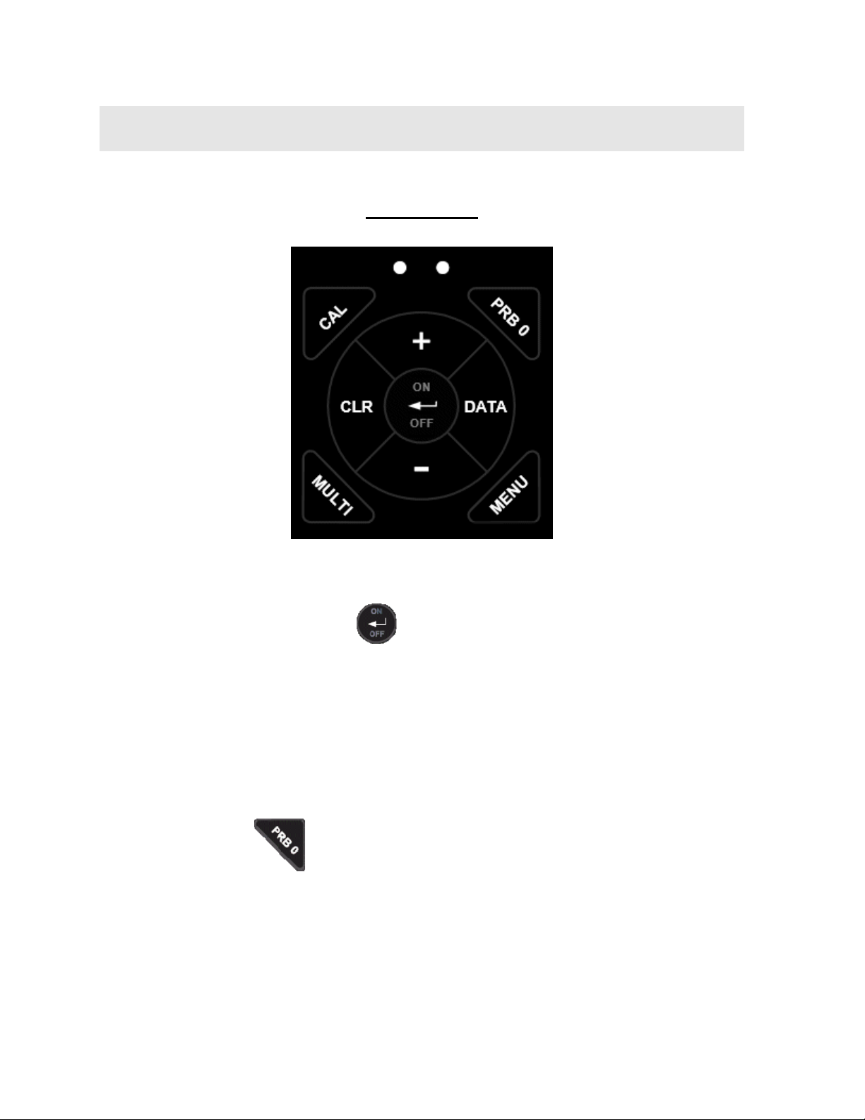
The Keypad
2.1 ON/OFF/ENTER Key
The ON/OFF/ENTER key powers the unit ON or OFF. Since the same key is also
used as an ENTER key, the gauge is powered off by pressing and holding down the
key until the unit powers off.
Once the gauge is initially powered on, this key will function as the ENTER key,
similar to a computer keyboard. This key will be used to select or set a menu option.
Note: Unit will automatically power off when idle for 5 minutes. All current settings
are automatically saved prior to powering off.
2.2 PRB 0 Key
The PRB 0 key is used to “zero” the ZX-6 DL in much the same way that a
mechanical micrometer is zeroed. If the gauge is not zeroed correctly, all of the
measurements that the gauge makes may be in error by some fixed value. Refer to
page 38 for a further explanation of this important feature.
2
Page 7
ZX- 6 DL Ultrasonic Multi-Mode Thickness Gauge
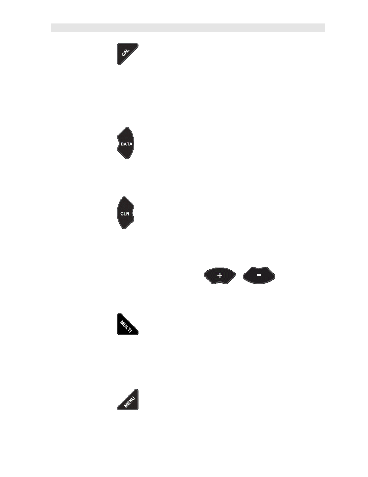
2.3 CAL Key
The CAL key is used to enter and exit the ZX-6 DL's calibration mode. This mode is
used to adjust the sound velocity value that the ZX-6 DL will use when calculating
thickness. The tool will either calculate the sound-velocity from a sample of the
material being measured, or allow a known velocity value to be entered directly. This
provides increased linearity between transducers. Refer to page 19 for an
explanation on the various calibration options.
2.4 DATA Key
The DATA key accesses the data logging section of the ZX-6 DL, which consists of
50 sequential (single column) files with 250 storage locations per file. Refer to page
44 for an explanation on the various calibration options.
2.5 CLR Key
The CLR key is used in conjunction with the data logging section to clear a single
stored memory location. Refer to page 44 for an explanation on the various
calibration options.
2.6 +/- Increment/Decrement Key’s
The +/- Keys are used to increment/decrement values, navigate menus, select menu
options, and navigate data files and storage locations.
2.7 MULTI Key
The MULTI key toggles between pulse-echo (P-E) and echo-echo (E-E)
measurement modes. (P-E) is used primarily for flaw and pit detection, while (E-E) is
used for through paint and coatings measurement without having to remove the
paint/coating and eliminating any error as a result of the paint/coating. Refer to page
25 for an explanation on the various calibration options.
2.8 MENU Key
3
Page 8
Dakota Ultrasonics
The MENU key is used to access and set all of the additional features of the ZX-6 DL
that are not at the top level of the keypad with a dedicated key. The features and
setting are outlined in the table below:
Menu Feature Items:
Gain Matl Scan Alarm Diff Unit Lite Beep Zero VX Probe
VLOW Aluminum On On On English On On Manual On .18 5
LOW Steel Off Off Off Metric Off Off Auto Off .18 5
MED Stainless Options Options Options .25 5
HIGH Iron Set Lo Set
Nominal
VHI Plexiglass Set Hi Med .50 3
PVC High .50 5
Plastic
Poly Urea
User 1
User 2
Lo .25 7
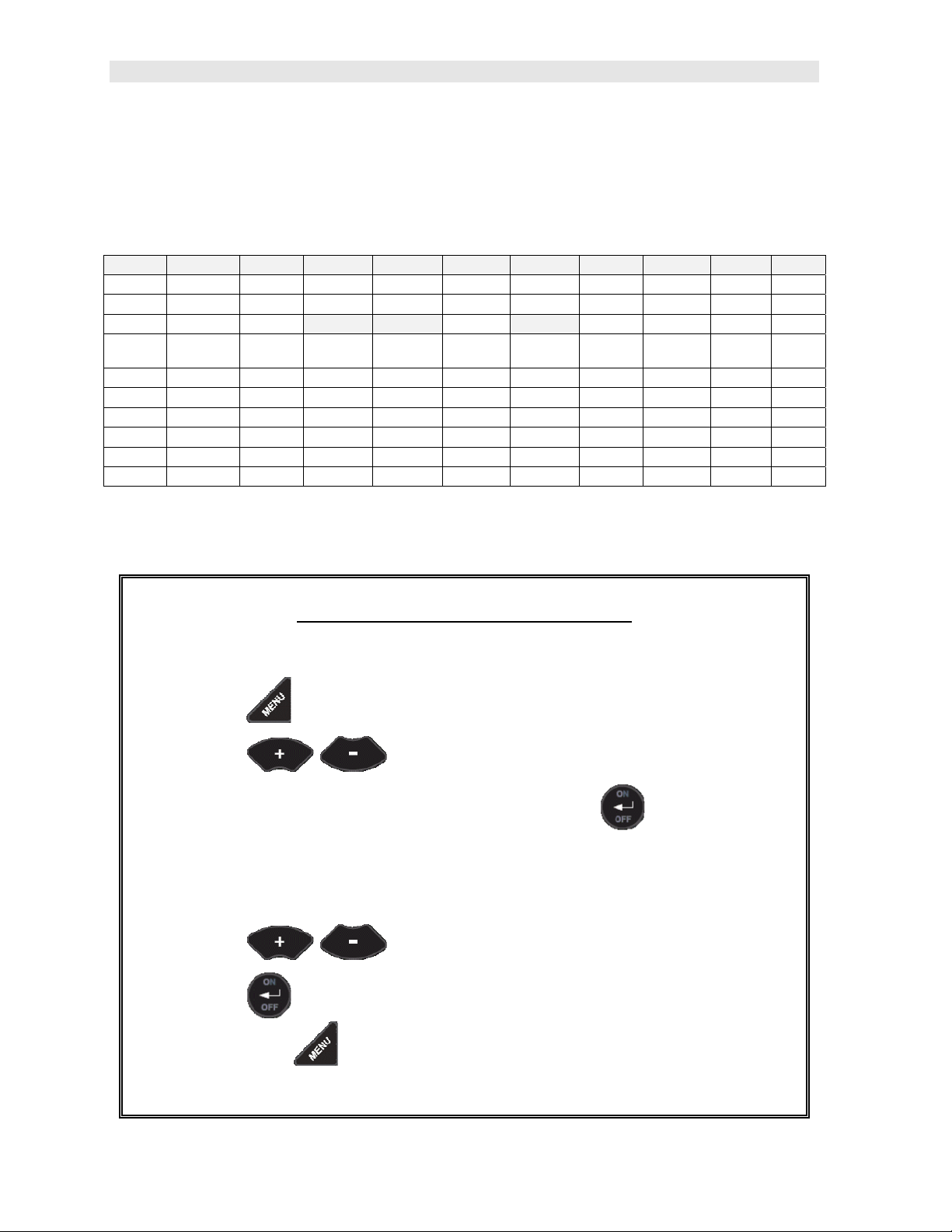
Here’s a quick overview of navigating through the various features in MENU:
Navigating the Features in Menu
1) Press the key once to enter the sub menu items.
2) Press the keys to toggle through the features.
3) To enable or edit the status of any feature, press the key.
4) The edit icon will start blinking to indicate that the ZX-6 DL is currently in
EDIT mode.
5) Press the keys to toggle through the setting options.
6) Press the key to accept changes and return to the top level of
features, or the key at any time to abort changes and return the
measurement screen.
4
Page 9
ZX- 6 DL Ultrasonic Multi-Mode Thickness Gauge
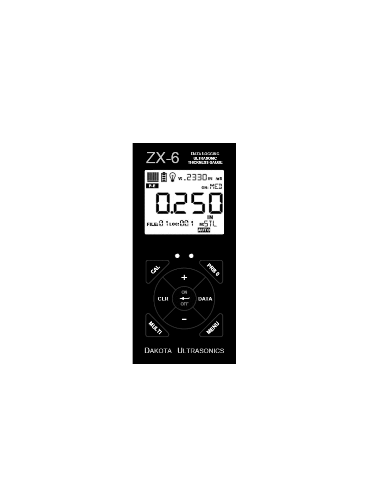
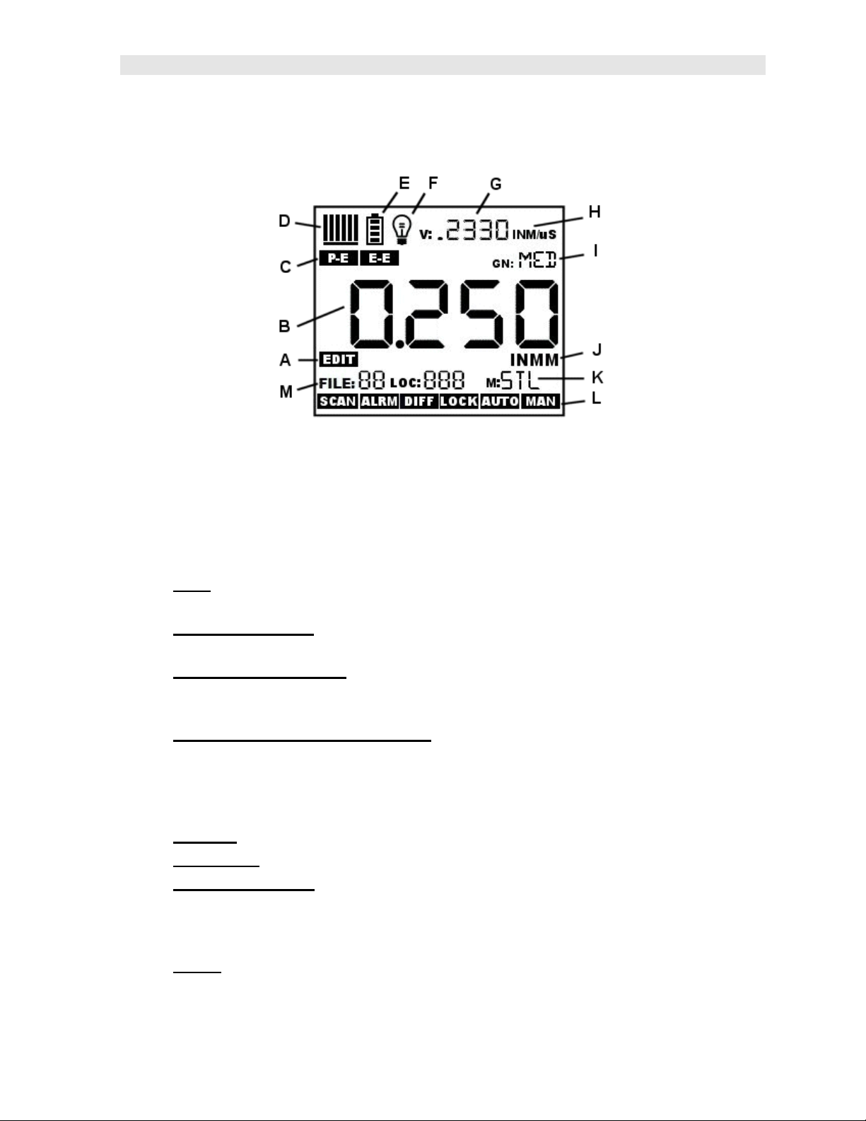
2.9 The Display
The ZX-6 DL uses a custom glass LCD backlit low temperature display for use in a
variety of climate conditions. It contains graphic icons, as well as both 7 and 14
segment display areas. Let’s take a closer look and what all these things are telling
us:
A. Edit: This icon will be displayed, and blinking, to let a user know when they
are in an edit mode to change a value or setting.
B. Large 7 segment: The thickness measurement, velocity or alpha message
will be displayed in this area.
C. Measurement Modes: This group of icons indicates which measurement
mode the ZX-6 DL is currently using. The modes are pulse-echo, for flaw and
pit detection, and echo-echo for through paint and coating measurements.
D. Stability/Repeatability Indicator:
thickness measurement as a reference for the validity of the measurement.
The ZX-6 DL takes multiple measurements per second, and when all the
vertical bars are illuminated, it’s a reference that the same thickness value is
reliably being measured multiple times per second.
E. Battery: Indicates the amount of battery life the ZX-6 DL has remaining.
F. Backlight : When this icon is illuminated, it indicates the backlight is on.
G. Small 7 Segment:
through a given medium/material, is displayed in this area, informing the user
what material the ZX-6 DL is currently calibrated too. This area is also used
for alpha messages in the menu and edit modes.
H. Units: This combination of icons are illuminated in different sequences to
inform the user what measurement units are currently being displayed in the
small 7 segment area.
The material velocity, speed the sound wave travels
This is used in conjunction with the
5
Page 10
Dakota Ultrasonics
I. Small 14 Segment: Displays the current gain setting of the ZX-6 DL. MED is
the default, with the options of VLOW, LOW, MED, HIGH, VHI (40dB to 52db
gain range with MED at 46dB).
J. Units: This combination of icons are illuminated in different sequences to
inform the user what measurement units are currently being displayed in the
large 7 segment area. The plus/minus icon is illuminated when the DIFF
(differential) feature is activated.
K. Small 14 Segment: The material type is displayed in this area. If it is set to a
value of one of the materials in our material list, it will be displayed in alpha
characters indicating the material type. Otherwise it will be set to CUST,
indicating custom material type.
L. Features: The icons illuminated in this row across the bottom of the LCD
display which features are currently enabled. For a complete list of the menu
features in the ZX-6 DL, Refer to page 4 for a list. The ZX-6 DL can be locked
once calibrated, to avoid accidently changing the calibration. When this icon is
illuminated, the ZX-6 DL is in lock mode. Refer to page 41 for an explanation
on locking the ZX-6 DL.
M. File/Loc: This area is exclusively for the data storage section of the ZX-6 DL.
The icons and segment fields represent the current file open, and the current
storage location in the file. Refer to page 44 for an explanation of the data
storage feature in the ZX-6 DL.
2.10 The Transducer
The Transducer is the “business end” of the ZX-6 DL. It transmits and receives
ultrasonic sound waves that the ZX-6 DL uses to calculate the thickness of the
material being measured. The transducer connects to the ZX-6 DL via the attached
cable, and two coaxial connectors. When using transducers manufactured by Dakota
Ultrasonics, the orientation of the dual coaxial connectors is not critical: either plug
may be fitted to either socket in the ZX-6 DL.
The transducer must be used correctly in order for the ZX-6 DL to produce accurate,
reliable measurements. Below is a short description of the transducer, followed by
instructions for its use.
6
Page 11
ZX- 6 DL Ultrasonic Multi-Mode Thickness Gauge
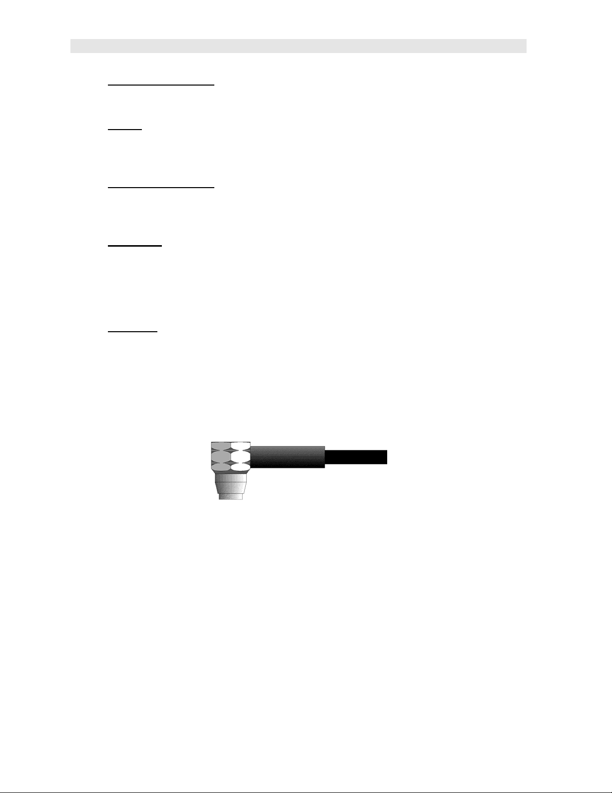
This is a bottom view of a typical transducer. The two semicircles of the wear face
are visible, as is the barrier separating them. One of the semicircles is responsible
for conducting ultrasonic sound into the material being measured, and the other
semicircle is responsible for conducting the echoed sound back into the transducer.
When the transducer is placed against the material being measured, it is the area
directly beneath the center of the wear face that is being measured.
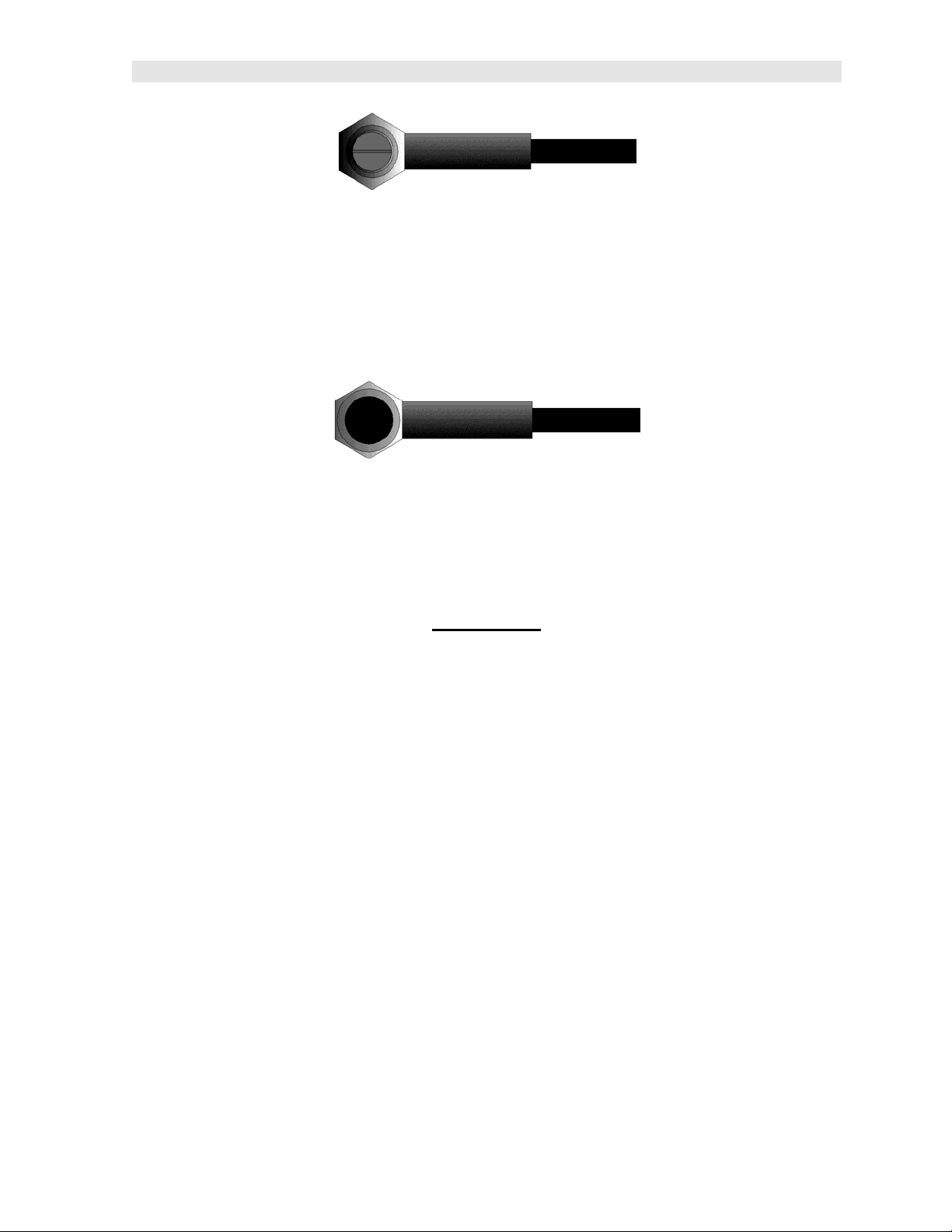
This is a top view of a typical transducer. Press against the top with the thumb or
index finger to hold the transducer in place. Moderate pressure is sufficient, as it is
only necessary to keep the transducer stationary, and the wear face seated flat
against the surface of the material being measured.
Measuring
In order for the transducer to do its job, there must be no air gaps between the wearface and the surface of the material being measured. This is accomplished with the
use of a "coupling" fluid, commonly called "couplant". This fluid serves to "couple", or
transfer, the ultrasonic sound waves from the transducer, into the material, and back
again. Before attempting to make a measurement, a small amount of couplant
should be applied to the surface of the material being measured. Typically, a single
droplet of couplant is sufficient.
After applying couplant, press the transducer (wear face down) firmly against the
area to be measured. The Stability Indicator should have six or seven bars
darkened, and a number should appear in the display. If the ZX-6 DL has been
properly "zeroed" (see page 16) and set to the correct sound velocity (see page 18),
the number in the display will indicate the actual thickness of the material directly
beneath the transducer.
If the Stability Indicator has fewer than five bars darkened, or the numbers on the
display seem erratic, first check to make sure that there is an adequate film of
couplant beneath the transducer, and that the transducer is seated flat against the
material. If the condition persists, it may be necessary to select a different transducer
7
Page 12
Dakota Ultrasonics
(size or frequency) for the material being measured. See page 14 for information on
transducer selection.
While the transducer is in contact with the material that is being measured, the ZX-6
DL will perform four measurements every second, updating its display as it does so.
When the transducer is removed from the surface, the display will hold the last
measurement made.
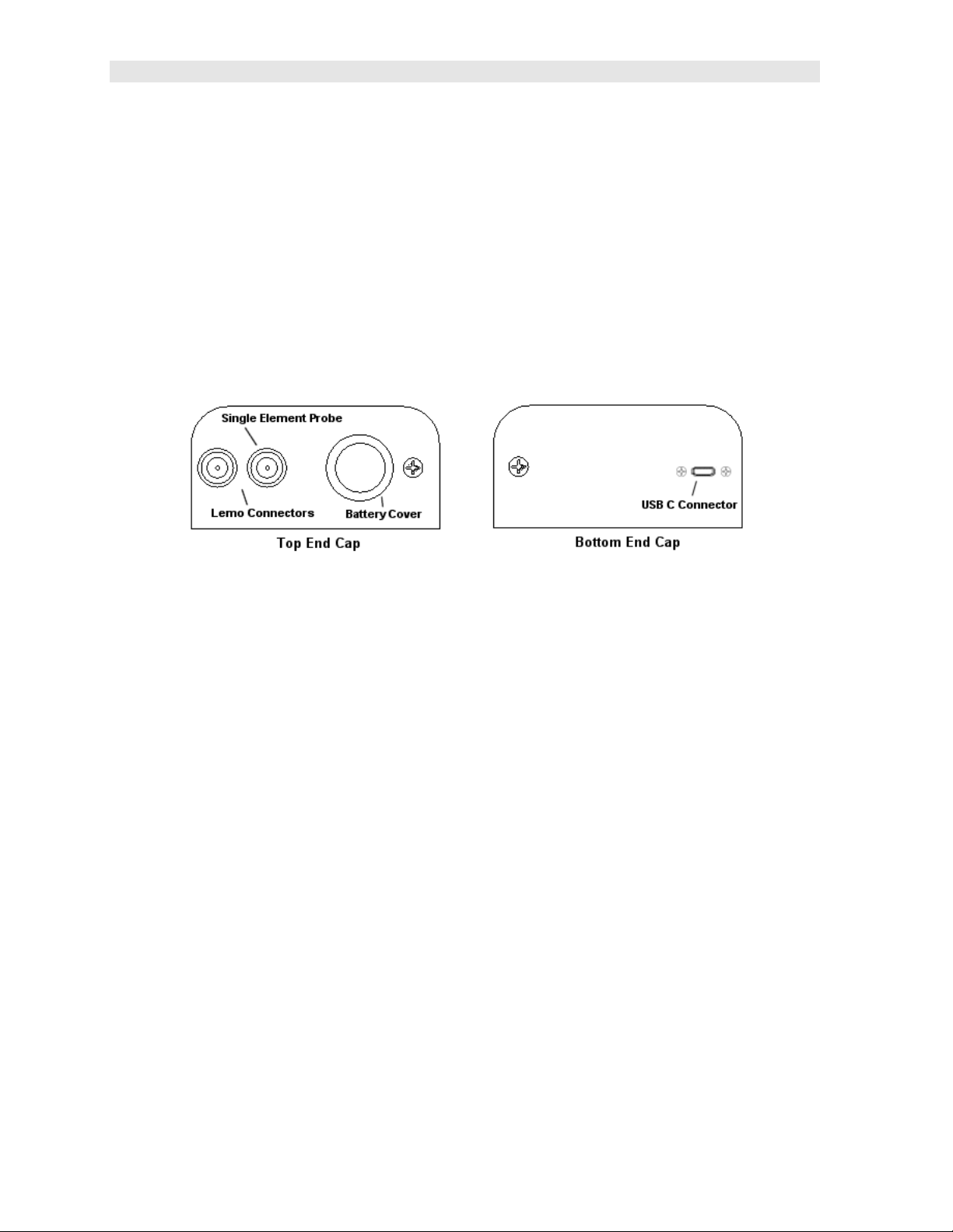
2.11 Top & Bottom End Caps
The top & bottom end panels are where all connections are made to the ZX-6 DL.
The diagram above shows the layout and description of the connectors:
Transducer Connectors
Refer to Diagram: The transducer connectors and battery cover/probe zero disk are
located on the ZX-6 DL’s top end cap. The transducer connectors are of type Lemo
“00”.
Note: There is no polarity associated with connecting the transducer to the ZX-6 DL,
it can be plugged into the gauge in either direction.
Probe Zero Disk & Battery Cover
Refer to Diagram: The Battery cover is the large round disk shown in the diagram.
Note: This same disk is also used as a probe zero disk when the zero feature is set
to the ‘manual’ option. Simply remove the cover when replacing the batteries (2 AA
cells). When performing a manual probe zero function, simply place the transducer
on disk making firm contact. Important: Be sure the battery polarity is correct,
which can be found on the back label of the ZX-6 DL.
Note: Rechargeable batteries can be used, however they must be recharged outside
of the unit in a standalone battery charger.
USB-C Connector
Refer to Diagram: The USB-C connector, located on the bottom end cap, is a mini
type C female connector. It is designed to connect directly from the ZX-6 DL to a
8
Page 13

ZX- 6 DL Ultrasonic Multi-Mode Thickness Gauge
standard USB type A port on a PC. The cable supplied with the ZX-6 DL is a USB
type C to a USB type A (pt# N-003-0330). See page 49 for information on
connectivity.
Note: This connector is also used to upgrade the ZX-6 DL with the latest version of
firmware.
9
Page 14

CHAPTER THREE
PRINCIPALS OF ULTRASONIC MEASUREMENT
3.1 Time versus thickness relationship
Ultrasonic thickness measurements depend on measuring the length of time it takes
for sound to travel through the material being tested. The ratio of the thickness
versus the time is known as the sound velocity. In order to make accurate
measurements, a sound velocity must be determined and entered into the
instrument.
The accuracy of a thickness measurement therefore depends on having a consistent
sound velocity. Some materials are not as consistent as others and accuracy will be
marginal. For example, some cast materials are very granular and porous and as a
result have inconsistent sound velocities.
While there are many different ultrasonic techniques to measure thickness, which will
be discussed below, all of them rely on using the sound velocity to convert from time
to thickness.
3.2 Suitability of materials
Ultrasonic thickness measurements rely on passing a sound wave through the
material being measured. Not all materials are good at transmitting sound.
Ultrasonic thickness measurement is practical in a wide variety of materials including
metals, plastics, and glass. Materials that are difficult include some cast materials,
concrete, wood, fiberglass, and some rubber.
3.3 Range of measurement and accuracy
The overall measurement capabilities, based on the wide variety of materials, is
determined by the consistency of the material being measured
The range of thickness that can be measured ultrasonically depends on the material
type and surface, as well as the technique being used and the type of transducer.
The range will vary depending on the type of material being measured.
Accuracy, is determined by how consistent the sound velocity is through the sound
path being measured, and is a function of the overall thickness of the material. For
example, the velocity in steel is typically within 0.5% while the velocity in cast iron
can vary by 4%.
3.4 Couplant
All ultrasonic applications require some medium to couple the sound from the
transducer to the test piece. Typically a high viscosity liquid is used as the medium.
The sound frequencies used in ultrasonic thickness measurement do not travel
through air efficiently. By using a liquid couplant between the transducer and test
piece the amount of ultrasound entering the test piece is much greater.
10
Page 15

ZX- 6 DL Ultrasonic Multi-Mode Thickness Gauge
3.5 Temperature
Temperature has an effect on sound velocity. The higher the temperature, the slower
sound travels in a material. High temperatures can also damage transducers and
present a problem for various liquid couplants.
Since the sound velocity varies with temperature it is important to calibrate at the
same temperature as the material being measured.
Normal temperature range
Most standard transducers will operate from 0F to 250F.
High temperature measurements
Special transducers and couplants are available for temperatures above 250F up to
1000F with intermittent contact. It is necessary to cool the transducer by
submerging it in water between measurements.
Modes and temperature errors
In addition to errors caused by velocity changing with temperature, some modes
(measurement techniques) are affected more than others. For example, dual
element pulse-echo mode has larger errors due to changes in the temperature of the
transducer. However, multi-echo techniques offer temperature compensation help to
minimize these errors.
3.6 Measurement Modes
This section will cover the different measurements modes of the ZX-6 DL, the
transducers required, and the reasons for using specific modes:
Pulse-Echo (P-E) Mode:
Pulse-echo mode measures from the initial pulse (sometimes referred to as an
artificial zero) to the first echo (reflection). In this mode, either an automatic or
manual zero can be performed depending on the zero probe setting. If the manual
mode has been selected, the transducer is placed on the reference disk located on
top of the ZX-6 DL, and the PRB 0 key pressed to establish a zero point for the
transducer connected. If the Auto Zero feature is enabled, simply pressing the PRB
0 key will perform an electronic zero to establish the same zero point.
In pulse-echo mode, errors can result from surface coatings and temperature
variations. Since pulse-echo only requires one reflection, it is the most sensitive
mode for measuring flaw/defects when measuring heavily corroded metals.
V-Path Correction
Dual element delay line transducers have two piezoelectric elements focused
towards one another at a slight angle, mounted on a delay line. One element is used
for transmitting sound, while the other element receives the sound reflection. The
11
Page 16
Dakota Ultrasonics
two elements and their delay lines are packaged in a single housing but acoustically
isolated from each other with an insulated sound barrier. This allows the transducer
the ability to achieve very high sensitivity for detecting small defects. Also, the
surface of the test material does not have to be as flat in order to obtain good
measurements.
Dual element transducers are normally used in pulse-echo mode for finding defects,
and in echo-echo mode for through coating measurements.
Dual element delay line transducers are have a usable range of 0.025” and up,
depending on the material, frequency, and diameter.
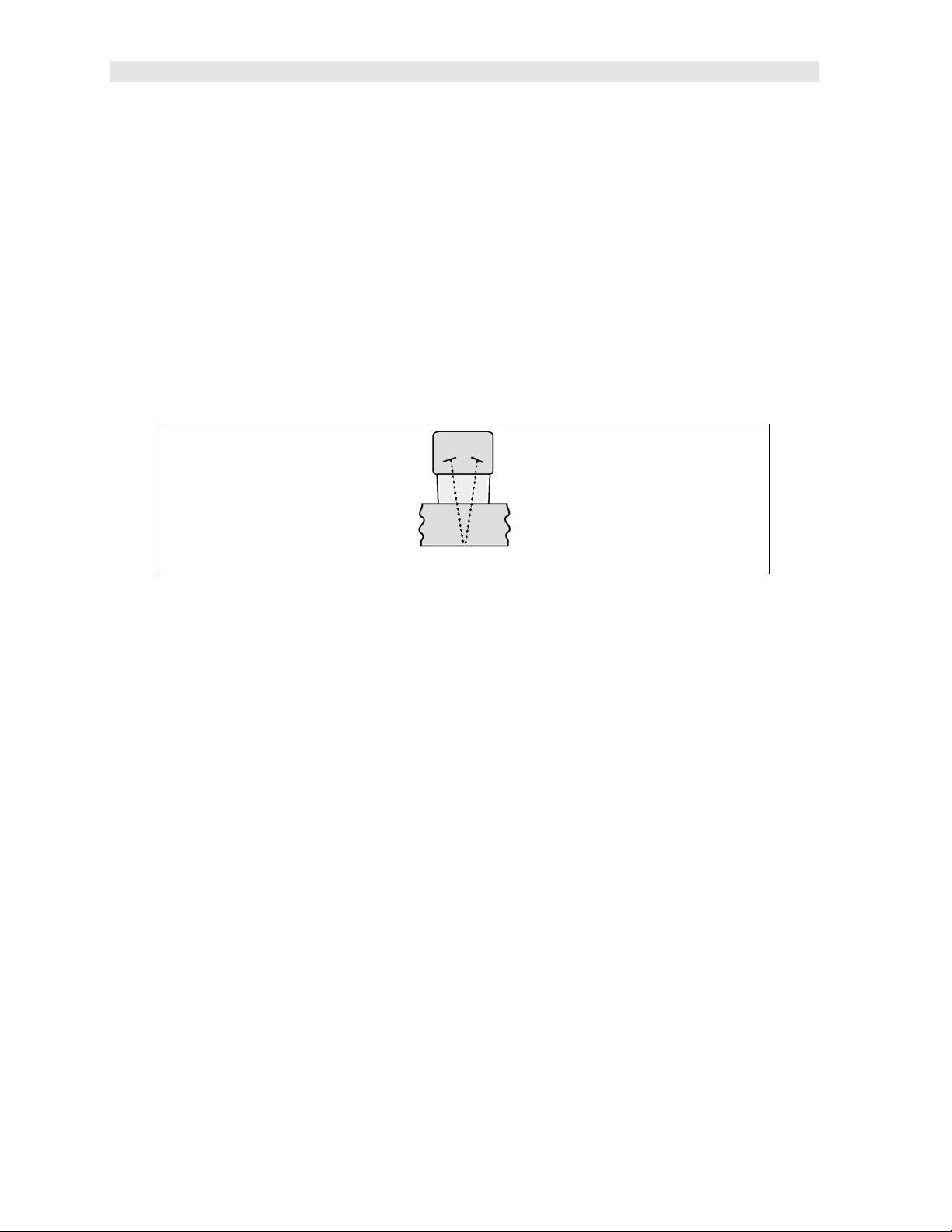
A limitation of dual element delay-line transducers is the V shaped sound path.
Because the sound travels from one element to another, the time versus thickness
relationship is non-linear. Therefore, a correction table in the instruments software is
used to compensate for this error.
Dual Element Transducer showing V-path of signal
Searching for small defects
Dual element delay line transducers are especially useful in searching for small
defects. In pulse-echo mode with high amplifier gain, very small defects can be
located. As a result, this configuration is commonly used for corrosion inspections.
The dual element style transducer will find wall deterioration, pits, cracks, and any
porosity pockets during tank and pipeline inspections.
Echo-Echo (E-E) Mode – Through Paint
The echo-echo mode measures between the first and second return
echoes/reflections. This technique is commonly used when measuring through a
surface coating and measuring only the second layer of material. Tanks and pipes
commonly have a protective coating applied to the surface. Echo-echo mode will
enable the user to measure just the steel without having to remove the coating. The
disadvantage is that two return echoes are required to effectively measure the test
material. Additionally, echo-echo mode does not have the capability to find defects.
Therefore, both modes will commonly be used; echo-echo mode to find the nominal
thickness of the material without removing the coating, and pulse-echo to locate
defects.
12
Page 17

ZX- 6 DL Ultrasonic Multi-Mode Thickness Gauge
Dual Element Transducer in Echo to Echo mode
13
Page 18

CHAPTER FOUR
SELECTING THE MEASUREMENT MODE
4.1 Which mode & transducer do I use for my application?
High penetration plastics and castings
The most common mode for these types of applications is pulse-echo. Cast iron
applications require 1 - 5MHz frequencies, and cast aluminum requires a 7 - 10MHz
frequency depending on the thickness. Plastics typically require lower frequencies
depending on the thickness and make-up of the material as well. Larger diameters
offer greater penetration power based on the size of the crystal.
Corrosion & Pit Detection in steel and cast materials
Pulse-echo mode is commonly used for locating pits and defects. Typically a 5MHz
transducer, or higher, will be used for these types of applications. Use low
frequencies for greater penetration and use higher frequencies for better resolution.
Measuring Material & Coatings
The pulse-echo coating mode should be used when both material and coating
thickness are required, while still requiring the ability to detect flaws and pits. A
special coating style transducer is required for use in this mode. There are a variety
of coating transducers in various frequencies available from Dakota.
Thru Paint & Coatings
Often times, users will be faced with applications where the material will be coated
with paint or some other type of epoxy material. Since the velocity of the coating is
approximately 3 times slower than that of steel, pulse-echo mode will result in an
error if the coating or paint is not completely removed. By using echo-echo mode,
the user is able to successfully measure through both the coating and steel, and
completely eliminate the thickness of the paint or coating. Therefore, the steel can
be measured without having to remove the coating prior to measuring. Users will
often use pulse-echo mode and echo-echo mode in conjunction when performing
inspections on coated materials.
Thru coating measurements require special high damped transducers. The most
common transducers are the 3.5, 5, and 7.5MHz hi damped transducers. These
transducers are suitable for use in both pulse-echo and echo-echo modes. This
conveniently enables the user to accurately measure overall material thickness using
the thru Coating mode, and then conveniently switch to pit detection mode without
changing transducers. The ¼” 5MHz Hi damped transducer is the most commonly
used transducer for standard thru coating applications.
14
Page 19

ZX- 6 DL Ultrasonic Multi-Mode Thickness Gauge
Thin materials
Pulse echo mode and a high frequency transducer is commonly used for these types
of applications. The most common transducers are the 7.5MHz and 10MHz models
with extra resolution. The higher frequencies provide greater resolution and a lower
minimum thickness rating overall.
High temperature
Special 5 MHz High temperature transducers are available for these types of
applications. Both pulse-echo and echo-echo modes will also work for these
applications. However, echo-echo mode will eliminate error caused by temperature
variations in the transducer.
Noisy Material
Materials such as titanium, stainless steel, and aluminum may have inherent surface
noise issues or mirroring effect. Higher frequency transducers 7 – 10MHz offer
improved resolution to avoid erroneous measurements.
Restricted access
Measuring materials with extreme curvatures or restricted access are best suited for
higher frequencies and smaller diameter transducers.
15
Page 20

CHAPTER FIVE
MAKING MEASUREMENTS
The steps involved in making measurements are detailed in this section. The
following sections outline how to setup and prepare your ZX-6 DL for field use.
An automatic or manual zero must always be performed. The auto zero is an ‘off
block’ electronic zero that does not require a zero reference standard. This will most
always be the zero option of choice, as it makes the zeroing process very easy and
convenient to perform. However, the manual zero option offers better accuracy in
terms of a reference point. If the manual zero option is enabled, the probe zero must
be measured on the reference disk (battery disk) attached to the top of the
instrument. The zero compensates for variations in the transducer. In either mode
the sound velocity must be determined, and is used to convert the transit time to a
physical length. The sound velocity can be selected from a material chart in the
manual, selected from a short list of common materials in the ZX-6 DL, or for greater
precision determined from a sample of the test material that has been mechanically
measured. To enter the velocity from a table, look up the material on the chart in the
appendix of this manual and refer to the section below on Calibration to a Known
Velocity. To determine the velocity of a single sample, refer to the Material
Calibration section on page 18.
When measuring curved materials, it’s more accurate to calibrate from two test
points, one at the minimum limit of the target thickness and one at the maximum limit.
In this case the reference disk mounted to the ZX-6 DL is not used. This is called
two-point calibration and is described on page 21.
5.1 Probe zero
Setting the zero point of the ZX-6 DL is important for the same reason that setting the
zero on a mechanical micrometer is important. It must be done prior to calibration,
and should be done throughout the day to account for any temperature changes in
the probe. If the ZX-6 DL is not zeroed correctly, all the measurements taken may be
in error by some fixed value. The zero can only be performed with the
measurement mode set to pulse-echo (P-E). Therefore, if the ZX-6 DL is to use the
echo-echo (E-E) measurement mode and a manual zero is being performed, the ZX-
6 DL will argue by briefly displaying the message “NO PRB0”.
Important note: The internal zero setting of the ZX-6 DL, used for the auto zero
mode, can be reset at anytime by performing a “manual zero”, and immediately
followed by performing an “auto zero”.
The ZX-6 DL is equipped with two zero options:
1) Off Block Zero (Automatic Probe Zero) – When this feature is enabled the
ZX-6 DL will do an electronic zero automatically, eliminating the need for a
zero disk or reference standard.
16
Page 21

ZX- 6 DL Ultrasonic Multi-Mode Thickness Gauge
2) On Block Zero (Manual Probe Zero) – When this feature is enabled the
transducer must be placed on the probe zero disk (battery cover) located on
the top of the unit.
Both zero procedures are outlined as follows:
Performing an Auto Probe Zero (Off Block)
1) Press the key to perform the auto zero. “AUTO” will be displayed on
the screen and flashing CLn/Prb (clean probe).
2) Make sure the couplant is wiped clean from the tip of the transducer to avoid
any zero error.
3) Press the key to perform the zero.
Performing a Manual Probe Zero (On Block)
Note: When the zero probe option is set to manual, the probe zero disk
(battery cap) located on the top of the gauge will be used as a zero standard.
1) Apply a drop of couplant on the transducer and place the transducer in
steady contact with the disk (battery cover) located at the top of the unit to
obtain a measurement.
17
Page 22

Dakota Ultrasonics
2) Be sure all six repeatability/stability bars in the top left corner of the display
are fully illuminated and stable, and last digit of the measurement is toggling
only +/- .001” (.01mm).
3) Press the key to perform the manual zero. “PRB0” will briefly be
displayed on the screen, indicating the zero calculation is being performed.
5.2 Material Calibration
In order for the ZX-6 DL to make accurate measurements, it must be set to the
correct sound velocity of the material being measured. Different types of materials
have different inherent sound velocities. For example, the velocity of sound through
steel is about 0.233 inches per microsecond, versus that of aluminum, which is about
0.248 inches per microsecond. If the gauge is not set to the correct sound velocity,
all of the measurements the gauge makes will be erroneous by some amount.
The One Point calibration is the simplest and most commonly used calibration
method - optimizing linearity over large ranges. The Two Point calibration allows for
greater accuracy over small ranges by calculating both the probe zero, as well as the
material velocity. The ZX-6 DL provides three simple methods for setting the sound-
velocity outlined below:
Known Velocity
If the material velocity is known, it can be manually entered into the ZX-6 DL, rather
than have the ZX-6 DL calculate the velocity value using a known thickness of the
same material type. The steps for entering the velocity are outlined below:
Using a Known Material Velocity
1) With the transducer free from contact with the material, press the key
to display the current velocity.
18
Page 23

ZX- 6 DL Ultrasonic Multi-Mode Thickness Gauge
2) Use the
value.
Note: The longer the keys are pressed and held, the faster the value will
increment/decrement.
Note: Pressing the key prior to pressing the key will abort the cal
routine without saving any changes.
3) Press the key to set the velocity value and return to the measurement
screen. The new velocity value will be shown at the top of the display.
keys to scroll the velocity to the known target
Known Thickness
Often times the exact sound velocity of a material is unknown. However, a sample
with one or two known thicknesses can be used to determine the sound velocity. As
previously discussed, the ZX-6 DL has a one or two point calibration option. The one
point calibration option is most suited for linearity over large ranges. When using the
one point option, the calibration should be perform on the thickest side of the
measurement range for the best linearity for that range. For example, if the
measurement range is .100” (2.54mm) to 1.0” (25.4mm), the user should calibrate on
a known thickness sample close to 1.0” (25.4mm). Note: It’s always handy to carry
a set of mechanical calipers to use in conjunction with the ZX-6 DL for calibration of
various materials in the field:
One Point Calibration
Note: Be sure that a probe zero has been performed prior to performing this
calibration procedure.
1) Physically measure an exact sample of the material, or a location directly on
the material to be measured, using a set of calipers or a digital micrometer.
19
Page 24

Dakota Ultrasonics
Note: A sample or location on the test piece should be used as close to the
maximum thickness of the test range to minimize error.
2) Apply a drop of couplant on the transducer and place the transducer in
steady contact with the sample or actual test material. Be sure that the
reading is stable and the repeatability indicator in the top left corner of the
display is fully lit and stable.
3) Press the key to enter the calibration edit screen displaying the current
measurement value.
4) Use the keys to scroll to the known thickness value.
Note: The longer the keys are pressed and held, the faster the value will
increment/decrement.
Note: Pressing the key prior to pressing the key will abort the cal
routine without saving any changes.
5) Once the known thickness value is being displayed, press the key to
display the calculated material velocity edit screen.
Note: The calculated velocity can be edited, if needed, by pressing the
keys to scroll and edit the velocity value.
6) Press the key to set the calculated material velocity and return to the
measurement screen.
Note: CHECK YOUR CALIBRATION! Place the transducer back on the
calibration point and verify the thickness. If the thickness is not correct, repeat
the steps above.
20
Page 25

ZX- 6 DL Ultrasonic Multi-Mode Thickness Gauge
Two Known Thicknesses
The two point calibration should be considered when an application requires
improved accuracy over a small measurement range based on tolerance
requirements. This calibration option calculates both the ‘probe zero’ and ‘velocity
value. If the two point option is used, a probe zero is not required. For example, if
the measurement range was .080” (2.03mm) to .250” (6.35mm), two known samples
or locations on the test material would be needed for the minimum and maximum
boundaries of the test range. Using the range above, a one point calibration would
be performed at .250” (6.35mm) and a two point calibration at .080” (2.03mm), or
something close to the min/max values of the measurement range.
Note: The ZX-6 DL also offers the capability of setting the ‘probe zero’ to use any
reference standard as the ‘probe zero’ standard. For clarification, if it’s desired to use
a one inch reference of a specific material type as the ‘zero’ reference, performing
the first point of a two-point calibration sets the internal zero of the ZX-6 DL. This
should be used only in manual probe zero mode “on block”.
The following steps outline this procedure:
Two Point Calibration
1) Physically measure a minimum and maximum calibration point of the exact
sample material, or locations directly on the material to be measured, using
a set of calipers or a digital micrometer.
Note: A sample or location on the test piece should be used as close to the
minimum and maximum thickness of the test range to minimize error and
improve linearity.
2) Apply a drop of couplant on the transducer and place the transducer in
steady contact with either the minimum or maximum sample or actual test
material. Be sure that the reading is stable and the repeatability indicator in
the top left corner of the display is fully lit and stable.
21
Page 26

Dakota Ultrasonics
3) Press the key to enter the calibration edit screen displaying the current
measurement value.
4) Use the keys to scroll to the known thickness value.
Note: The longer the keys are pressed and held, the faster the value will
increment/decrement.
Note: Pressing the key prior to pressing the key will abort the cal
routine without saving any changes.
5) Once the known thickness value is being displayed, press the key to
display “1 of 2”, which sets the zero value and returns to the measurement
screen.
Note: The internal zero of the ZX-6 is now set. The procedure above can be
used to set the internal zero of the ZX-6 to use any reference standard as
the ‘probe zero’ standard if desired.
6) Repeat steps 2-4 on the second test point/location.
7) Press the key to display the calculated velocity edit screen.
Note: The calculated velocity can be edited, if needed, by pressing the
keys to scroll and edit the velocity value.
8) Press the key to set the calculated material velocity and return to the
measurement screen.
Note: CHECK YOUR CALIBRATION! Place the transducer back on the
calibration points. The thickness readings should now match the known
22
Page 27

ZX- 6 DL Ultrasonic Multi-Mode Thickness Gauge
thickness values with minimal error. If the thicknesses are not correct, repeat
the steps above.
Basic Material Type
If the material velocity is unknown, a sample thickness cannot be taken directly from
the material, but the general type of material is known, selecting a basic material type
from the common material (MATL) list in the ZX-6 DL would offer a reasonable
approximation of the thickness. There are 9 common materials and 2 user
programmable settings available. It’s important to note that these velocities will not
always be an exact representation of the material being tested. Use these values
only if a close approximation is acceptable. Follow the steps below to select a basic
material type:
Selecting a Basic Material Type
1) Press the key to access the menu items/features.
2) Use the keys to scroll through the items/features until the
MATL feature is being displayed.
3) Press the key to edit the material setting. The edit icon will be
illuminated and flashing.
Note: Pressing the key prior to pressing the key will abort to the
measurement screen without saving any changes.
4) Use the keys to scroll through the material options.
23
Page 28

Dakota Ultrasonics
ALUMINUM
(2024)
STEEL (4340)
in/µs m/s
0.250 6350
0.233 5918
STAINLESS (303)
CAST IRON
PLEXIGLASS
PVC
POLYSTYRENE
POLYURETHANE
USER PROGRAMMABLE
0.223 5664
0.180 4572
0.106 2692
0.094 2388
0.092 2337
0.070 1778
5) When the desired MATL setting is displayed, press the key to set the
material velocity and return to the measurement screen.
Note: Pressing the key prior to pressing the key will abort to the
measurement screen without saving any changes.
6) If USR1 or USR2 were selected, the velocity edit screen will be displayed
and edit icon illuminated and flashing.
7) Use the keys to scroll to the desired material velocity.
Note: The longer these keys are held, the faster the velocity value is
incremented.
8) When the desired velocity setting is displayed, press the key to set the
material velocity and return to the measurement screen.
9) Note: Pressing the key prior to pressing the key will abort to the
measurement screen without saving any changes.
24
Page 29

CHAPTER SIX
THROUGH PAINT MEASUREMENT - MULTI MODE
6.1 Introduction
Through paint measurement is accomplished by measuring the time between two
repeat echoes from the back surface of the material. Since both of these back wall
echoes travel the same path through the paint or coating, the thickness of the coating
is subtracted out of the measurement so that only the actual material thickness is
measured. This avoids having to scrape or remove the coating from materials prior
to inspection. The primary purpose of thru paint measurement is to determine the
actual/nominal material thickness without error from the coating.
Through paint mode cannot be used for flaw or pit detection based on the internal
gating and thresholds. As a result, inspectors will typically use both echo-echo
through paint mode in conjunction with the standard pulse-echo flaw detection mode
for coated material and corrosion inspection. Finally, this mode will only work for
typical epoxy based coatings.
6.2 Multi Mode Transducers
The multi echo measurement technique does have restrictions on the type of dual
element transducers it can use successfully. The key requirement is that the
transducers are “high damped”, which refers to the duration of how long the
transducer rings. In order to improve the low end measurement range, being able to
measure thin materials, the cycles of ring must be limited so they don’t interfere with
the internal gating.
Since the ZX-6 DL is a basic easy to operate gauge without the adjustability you’d
get using an advanced A-Scan scope, specific diameter and frequency options can
be selected as an option in the menu items. The factory default setting is (.25 5) or
0.250” 5MHz, as the most commonly requested transducer. Refer to page 4 for a list
of available high damped transducer diameters and frequencies.
The procedure for activating the through paint (E-E) measurement mode is outlined
as follows:
Echo-Echo Multi Mode
25
Page 30

Dakota Ultrasonics
Note: Be sure that a probe zero and “one point calibration”, or a “two point
calibration” has been performed prior to this procedure.
1) Press the key to toggle between the measurement modes; pulse-echo
(P-E) and echo-echo (E-E) at any time.
Note: An icon will be illuminated in the top left portion of the display to indicate
the measurement mode the ZX-6 DL is currently using.
26
Page 31

CHAPTER SEVEN
VELOCITY GAUGE
7.1 Velocity Gauge (VX)
The ZX-6 DL includes a function to convert the unit into a dedicated velocity gauge.
With this feature enabled, the ZX-6 DL will display all measurements in terms of
velocity, inches per microsecond (IN /s) or meters per second (M /s), rather than
dimensional inches or millimeters. This is primarily useful for rudimentary “nodularity”
testing, as the velocity can be associated with density and used to determine the
hardness/strength of a given material. A casting manufacturer would typically use
this feature to control their processes and make sure the density/hardness is
sufficient for each part and batch within a specified tolerance.
Using this feature will require calibration on a “known” thickness that will remain
consistent at a specific location on a group of parts. The test will always be
performed at the same location for all parts in the group. The velocity will be
determined, and either accepted or rejected depending on the specified tolerances.
The procedure for enabling this feature is outlined below:
Velocity Gauge Option
1) Press the key to access the menu items/features.
2) Use the keys to scroll through the items/features until the
VX feature is being displayed.
3) Press the key to edit the velocity gauge setting. The edit icon will be
illuminated and flashing.
4) Use the keys to toggle velocity on/off.
Note: Pressing the key prior to pressing the key will abort to the
measurement screen without saving changes.
27
Page 32

Dakota Ultrasonics
5) When the desired VX setting is displayed, press the key to set the
status and return to the measurement screen.
7.2 Calibration to a known thickness
In order to calibrate the ZX-6 DL a ‘known thickness’ on the material or part will be
used. The same location will be used for all the other parts in the group/batch to
determine the velocity.
The procedure is outlined as follows:
Calibration – Known Thickness
Note: Be sure that a probe zero has been performed prior to performing this
calibration procedure.
1) Physically measure an exact sample of the material, or a location directly on
the material to be measured, using a set of calipers or a digital micrometer.
2) Apply a drop of couplant on the transducer and place the transducer in
steady contact with the sample or actual test material. Be sure that the
reading is stable and the repeatability indicator, in the top left corner of the
display, is fully lit and stable.
3) Press the key to enter the calibration edit screen displaying the current
velocity IN /s (M /s) value. The edit icon will be illuminated and flashing.
4) Press the key again to edit the known thickness value. The edit icon
will be illuminated and flashing and the units will be IN or MM, indicating
thickness.
28
Page 33

ZX- 6 DL Ultrasonic Multi-Mode Thickness Gauge
5) Use the keys to scroll to the known thickness value.
Note: The longer the keys are pressed and held, the faster the value will
increment/decrement.
Note: Pressing the key prior to pressing the key will abort the cal
routine without saving any changes.
6) Once the known thickness value is being displayed, press the key to
return to the measurement screen and display the calculated material
velocity.
Note: The known thickness value that was used to calibrate will be displayed in
the top right corner of the display for confirmation.
7.3 Calibration to a known velocity
The velocity can also be directly edited and set to a target velocity value that was
previously determined from a reference standard at an earlier time.
The procedure for directly entering the velocity is outlined below:
Calibration – Known Velocity
Note: Be sure that a probe zero has been performed prior to performing this
calibration procedure.
Note: This procedure requires that the operator know the sound-velocity of the
material to be measured. A table of common materials and their sound-
velocities can be found in Appendix A.
29
Page 34

Dakota Ultrasonics
1) Apply a drop of couplant on the transducer and place the transducer in
steady contact with the sample or actual test material. Be sure that the
velocity measurement is stable and the repeatability indicator, in the top left
corner of the display, is fully lit and stable.
2) Press the key to enter the calibration edit screen displaying the current
velocity IN /s (M /s) value. The edit icon will be illuminated and flashing.
3) Use the keys to scroll to the known velocity value.
Note: Pressing the key prior to pressing the key will abort the cal
routine without saving any changes.
4) Once the known velocity value is being displayed, press the key to
display the calculated thickness based on known velocity.
5) Press the key to return to the measurement screen and begin making
measurements.
Note: The known velocity value that was entered will be displayed, and the
thickness value calculated will appear in the top right corner of the display
for confirmation.
30
Page 35

CHAPTER EIGHT
ADDITIONAL FEATURES
8.1 Gain
The gain, or amplification of the return echoes, can be adjusted in the ZX-6 DL to
accommodate a variety of materials and applications. The setting of the gain is
crucial in order to obtain valid readings during the measurement process. Too much
gain may result in erroneous measurements, detecting on noise rather than the
actual material back wall surface. Not enough gain may result in intermittent
detection. It could also result in lack of detection on internal flaws, pits, or porosity.
The gain can be compared to the volume control of a home stereo system. If you
turn it up too much, you can’t hear the music clearly. If it’s turned down too much,
you can’t hear it at all.
The ZX-6 DL has five gain settings (VLOW, LOW, MED, HIGH, VHI). The gain
range is 40dB – 52dB in 3dB increments. The ZX-6 DL has been optimized for the
MED gain setting at 46dB for all common applications. It should be operated in this
mode as standard. However, some applications may require the lower or higher gain
settings. When? The low settings may be necessary for noisy or granular cast
materials. How do I know when to lower the gain? If the reading becomes sporadic
and won’t settle down or resolve on a thickness value because the material is either
very noisy or granular. Setting the gain to a lower less sensitive level, would
potentially offer improved stability.
How do I know when to increase the gain? When a material is difficult to penetrate or
pass sound through. This could be due to the material type, overall thickness, the
transducer diameter and frequency, or a combination of all the above. Turning the
gain up for additional output could improve the ability to obtain a successful
measurement. Another example would be the need to increase overall sensitivity for
locating fine pits or flaws. In any case, the selectable gain settings offer improved
versatility to resolve and overcome potential application issues.
Note: When the echo-echo through paint measurement mode is selected, the
automatic gain control (AGC) is enabled. The dynamic range of the AGC can be
adjusted with the following options (LOW, MED, HIGH), with MED still being the
optimized standard setting as above.
The procedure for editing the gain is outlined as follows:
GAIN
31
Page 36

Dakota Ultrasonics
1) Press the key to access the menu items/features.
2) Use the keys to scroll through the items/features until the
GAIN feature is being displayed.
3) Press the key to edit the gain setting. The edit icon will be illuminated
and flashing.
4) Use the keys to scroll through the gain settings in P-E
(VLOW, LOW, MED, HIGH, VHI), or E-E (LOW, MED, HIGH) until the
desired setting is being displayed.
Note: Pressing the key prior to pressing the key will abort to the
measurement screen without saving changes.
5) Press the key to set the gain and return to the measurement screen.
Note: Pressing the key prior to pressing the key will abort to the
measurement screen without saving changes.
8.2 High Speed Scan
The High Speed Scan feature of the ZX-6 DL increases the overall repetition rate to a
maximum of 140Hz with a high speed screen refresh rate of 25 times a second. This
allows for making scanned passes over an arbitrary length of the test material, while
still maintaining a reasonable representation of thickness over the area or region
scanned. The alarm (ALRM) feature, with high and low limits, can be used in
conjunction with high speed scan.
The procedure to use the scan feature is outlined below:
High Speed Scan
32
Page 37

ZX- 6 DL Ultrasonic Multi-Mode Thickness Gauge
1) Press the key to access the menu items/features.
2) Use the keys to scroll through the items/features until the
SCAN feature is being displayed.
3) Press the key to edit the scan setting. The edit icon will be illuminated
and flashing.
4) Use the keys to toggle scan on/off.
Note: Pressing the key prior to pressing the key will abort to the
measurement screen without saving changes.
5) When the desired SCAN setting is displayed, press the key to set the
status and return to the measurement screen.
8.3 Alarm
The Alarm feature of the ZX-6 DL provides a method of setting tolerances, or limits,
for a particular application requirement. This feature may be used for a variety of
applications to verify the material thickness is within the manufacturer specifications.
The settings available are ON/OFF/BEEP, where beep enables the audible beeper.
Both the on and beep settings will illuminate the led alarm lights above the keys on
the keypad. There are two limit values HI/LO, that can be set according to specified
tolerances.
The procedure to use the alarm feature is outlined below:
ALARM
1) Press the key to access the menu items/features.
33
Page 38

Dakota Ultrasonics
2) Use the keys to scroll through the items/features until the
ALRM feature is being displayed.
3) Press the key to edit the alarm status. The edit icon will be illuminated
and flashing.
4) Use the keys to toggle alarm on/off/beep.
5) When the desired ALRM status is displayed, press the key to set the
status and edit the LO limit option.
6) Use the keys to scroll the LO limit value to the target value.
Note: Pressing the key prior to pressing the key will abort to the
measurement screen without saving changes to the LO limit value.
7) When the target LO limit is displayed, press the key to set the value
and advance to setting HI limit option.
8) Use the keys to scroll the HI limit value to the target value.
Note: Pressing the key prior to pressing the key will abort to the
measurement screen without saving changes to the HI limit value.
9) When the target HI limit is displayed, press the key to set the value
and return to the measurement screen.
8.4 Differential
The Differential Mode of the ZX-6 DL provides the user with the ability to set a
nominal value, according to what the expected thickness should be, and measure the
+/- difference from the nominal value entered. This feature is typically used in QA
incoming inspections on pipes, plate stock, coils, etc.
34
Page 39

ZX- 6 DL Ultrasonic Multi-Mode Thickness Gauge
The steps below outline how to enable and enter the nominal value to use this
feature:
Differential
1) Press the key to access the menu items/features.
2) Use the keys to scroll through the items/features until the
DIFF feature is being displayed.
3) Press the key to edit the differential status. The edit icon will be
illuminated and flashing.
4) Use the keys to toggle differential on/off.
5) When the desired DIFF setting is displayed, press the key to set the
status and edit the NOMINAL value.
6) Use the keys to scroll the NOMINAL value to the target
value.
Note: Pressing the key prior to pressing the key will abort to the
measurement screen without saving changes to the NOMINAL value.
7) When the target value is displayed, press the key to set the value and
return to the measurement screen.
8.5 Units
The ZX-6 DL will operate in both English (inches) or Metric (millimeters) units.
The procedure to select the units is outlined as below:
35
Page 40

Dakota Ultrasonics
Units
1) Press the key to access the menu items/features.
2) Use the keys to scroll through the items/features until the
UNIT feature is being displayed.
3) Press the key to edit the units setting. The edit icon will be illuminated
and flashing.
4) Use the keys to toggle English or Metric units.
Note: Pressing the key prior to pressing the key will abort to the
measurement screen without saving changes.
5) When the desired UNIT setting is displayed, press the key to set the
units and return to the measurement screen.
8.6 Lite
The ZX-6 DL uses a custom glass segmented display that is equipped with a
backlight for use in low light conditions. The options are on/off/auto, where the auto
setting only lights the display when the gauge is coupled to the material and receiving
a measurement.
The steps below outline how to toggle the options:
Backlight
36
Page 41

ZX- 6 DL Ultrasonic Multi-Mode Thickness Gauge
1) Press the key to access the menu items/features.
2) Use the keys to scroll through the items/features until the
LITE feature is being displayed.
3) Press the key to edit the light setting. The edit icon will be illuminated
and flashing.
4) Use the keys to toggle status on/off/auto.
Note: Pressing the key prior to pressing the key will abort to the
measurement screen without saving changes.
5) When the desired LITE setting is displayed, press the key to set the
status and edit the BRT (brightness) option.
6) Use the keys to scroll through the BRT (LO, MED, HI)
options.
7) When the desired BRT setting is displayed, press the key to set the
brightness and return to the measurement screen.
8) Note: Pressing the key prior to pressing the key will abort to
the measurement screen without saving changes.
8.7 Beep
The ZX-6 DL also has a feature to use the internal beeper, most commonly used with
the alarm feature, for the key strokes on the keypad. When enabled, pressing any of
the keys on the keypad will sound the beeper.
The procedure to enable the keyboard beeper feature is outlined below:
37
Page 42

Dakota Ultrasonics
Beeper
1) Press the key to access the menu items/features.
2) Use the keys to scroll through the items/features until the
BEEPER feature is being displayed.
3) Press the key to edit the beeper setting. The edit icon will be
illuminated and flashing.
4) Use the keys to toggle the beeper on/off.
Note: Pressing the key prior to pressing the key will abort to the
measurement screen without saving changes.
5) When the desired BEEP setting is displayed, press the key to set the
status and return to the measurement screen.
8.8 Zero
There are two transducer zeroing options available in the ZX-6 DL; auto and manual.
The AUTO zero can be performed automatically without using a reference standard
to zero the gauge, while the MANUAL option requires a reference standard like the
battery disk at the top of the gauge. Additionally, the gauge can be set to use
another reference standard if needed. Refer to page 38 for a complete explanation
of the probe zero options.
The procedure to select the zero option only, is outlined below:
Zero (Auto/Manual)
38
Page 43

ZX- 6 DL Ultrasonic Multi-Mode Thickness Gauge
1) Press the key to access the menu items/features.
2) Use the keys to scroll through the items/features until the
ZERO feature is being displayed.
3) Press the key to edit the zero setting. The edit icon will be illuminated
and flashing.
4) Use the keys to select the auto/man option.
Note: Pressing the key prior to pressing the key will abort to the
measurement screen without saving changes.
5) When the desired ZERO setting is displayed, press the key to set the
status and return to the measurement screen.
8.9 Velocity (VX)
When the velocity setting (VX) is enabled, the ZX-6 DL will display the material
velocity as the primary measurement quantity instead of dimensional thickness. The
feature is generally used for basic “nodularity” testing, as velocity is a key part of
density for determining hardness. An example might be casting manufacturers
where the density/hardness will determine the strength of the material.
When this feature is enabled, the ZX-6 DL is operating in reverse to the standard
option of the gauge. Only the ‘one point’ calibration can be used with this feature
active, and a manual or auto zero is still required. The ZX-6 DL can be calibrated by
entering the known velocity or entering the know thickness of the material at a given
position on the test material. Refer to the ‘making measurements’ section on page
27 for a complete explanation of the zero and one point calibration procedure.
The procedure to enable the velocity feature is outlined below:
Velocity Gauge
39
Page 44

Dakota Ultrasonics
1) Press the key to access the menu items/features.
2) Use the keys to scroll through the items/features until the
VX feature is being displayed.
3) Press the key to edit the setting. The edit icon will be illuminated and
flashing.
4) Use the keys to select the on/off option.
Note: Pressing the key prior to pressing the key will abort to the
measurement screen without saving changes.
5) When the desired VX setting is displayed, press the key to set the
status and return to the measurement screen.
8.10 Probe Diameter & Frequency
The PROB feature was added to improve linearity when using a specific probe
diameter and frequency. The default standard setting is (.25 5) 0.250” 5MHz Hi
Damped, and works reasonably well using a general correction curve for all of our
dual element transducers in the range. However, selecting the exact diameter and
frequency of the transducer will offer additional linearity (accuracy). The five options
found in our range of transducers are (.18 5, .18 7, .25 5, .25 7, .50 3, .50 5),
diameter followed by frequency (inches). All of our transducer diameters and
frequencies are marked on top of the transducer housing.
The procedure to select the probe/transducer diameter and frequency is outlined
below:
Probe
40
Page 45

ZX- 6 DL Ultrasonic Multi-Mode Thickness Gauge
1) Press the key to access the menu items/features.
2) Use the keys to scroll through the items/features until the
PROB feature is being displayed.
3) Press the key to edit the diameter/frequency setting. The edit icon will
be illuminated and flashing.
4) Use the keys to select the diameter/frequency option.
Note: Pressing the key prior to pressing the key will abort to the
measurement screen without saving changes.
5) When the desired PROB setting is displayed, press the key to select
the probe type and return to the measurement screen.
8.11 Lock
The lock feature was built into the ZX-6 DL for the purpose of locking the operators
out of editing any of the gauge settings, for purposes of consistency between
operators. When the lock feature is enabled, the gauge calibration functionality
cannot be altered, as well as any of the individual features in the gauge. The only
keys that are always unlocked are the power and probe zero keys, as these must
remain unlocked for measurement functionality.
The procedure to enable/disable the lock feature is outlined below:
Lock
41
Page 46

Dakota Ultrasonics
1) With the ZX-6 DL powered off, press and hold down the key while
powering the ZX-6 DL on . The lock icon will be illuminated on the
display.
2) To unlock the ZX-6 DL repeat step one, but hold down the key
while powering the ZX-6 DL on .
8.12 Factory Defaults
The ZX-6 DL can be reset to factory defaults at any time to restore the original gauge
settings. This should only be used if the gauge is not functioning properly, or
perhaps multiple features have been enabled and a clean start is needed.
The procedure to reset the gauge is outlined below:
Factory Reset
1) With the ZX-6 DL powered off, press and hold down the and
keys while powering the ZX-6 DL on .
Note: Once the measurement screen is displayed the and can be
released.
2) Press the keys to scroll through the factory setting options.
3) Make a note of the “MEDI” & “ZERO” settings prior to performing a reset.
These values will need to be entered back in the gauge following the reset.
4) Press the keys to scroll “REST” (reset).
42
Page 47

ZX- 6 DL Ultrasonic Multi-Mode Thickness Gauge
5) Press the key to edit the reset option.
6) Press the keys to toggle YES, followed by pressing
to reset the gauge.
7) Repeat the steps above to set “MEDI” & “ZERO” back to their original
settings noted in step three above.
43
Page 48

CHAPTER NINE
DATA STORAGE
9.1 Introduction
The ZX-6 DL is equipped with a basic and convenient sequential style data logger
that’s intuitive to operate. By ‘sequential’ meaning a single column of 250
measurements and a total of 40 individual files, for a total storage capacity of 10,000
measurements. These files can then be transferred to a PC using the USB-C to USB
type A cable included in the kit. When ZX-6 DL is connected to a PC, it will show up
in the list of drives as an external hard drive, or “thumb” drive. Open the external
gauge drive, and copy the files to and from the gauge and PC.
The file format is .csv (comma separated) and can be opened using any text editor,
spreadsheet editor, or Dakota’s proprietary PC software supplied with the gauges.
Only files with at least one measurement stored in the file will appear in the external
drive folder.
9.2 Opening a Data File
Open Data File
1) Press the key to access the data files and display the current file open.
2) Press the key to edit which file to open. The edit icon will be
illuminated and flashing.
3) Use the keys to scroll through the files.
Note: Pressing the key prior to pressing the key will abort to the
measurement screen without saving any changes.
44
Page 49

ZX- 6 DL Ultrasonic Multi-Mode Thickness Gauge
4) When the desired FILE is displayed, press the key to open the file and
return to the measurement screen.
Note: The FILE and LOC (location) will be displayed in lower left portion of the
measurement screen.
9.3 Storing a Measurement
Now that a file has been selected and opened, the ZX-6 DL is ready to store
measurements.
The following procedure outlines this process:
Storing Data
1) Use the keys to scroll to the desired location to store a
measurement.
2) Press the key to store a measurement and advance to the next
location (LOC).
3) Repeat steps 1 and 2 as needed.
Note: If an area exists where a measurement cannot be obtained successfully,
press the key to store OBST (obstruction) in the location. Pressing the
again will clear the location.
Note: If a measurement has been previously stored in a location, scrolling to
that location will display the measurement currently stored, and show MEM
45
Page 50

Dakota Ultrasonics
(memory) in the top right corner of the display. If the key is pressed
to store another measurement at that location, FULL will briefly be
displayed on the screen indicating a measurement has already been stored
at that location. Pressing the key will clear the previously stored
measurement from the location. Pressing the key will now store the
new measurement.
9.4 Clearing a File
If a file contains a large number of previously stored measurements, and has already
been downloaded, the file will need to be cleared of its measurements.
The following procedure outlines this process:
Clear File
1) Press the key to access the data files and display the current file open.
2) Press the key to edit which file will be cleared. The edit icon will be
illuminated and flashing.
3) Use the keys to scroll to the file that will be cleared.
4) When the desired FILE is being displayed, press the key to select the
file to be cleared.
5) Use the keys to scroll to CLR (clear).
46
Page 51

ZX- 6 DL Ultrasonic Multi-Mode Thickness Gauge
6) Press the key to display the confirmation screen. CLR? will be
displayed, as well as a flashing Yes/No option.
7) Press the key for YES, and the key for NO. The edit icon
will be illuminated and flashing.
Note: Pressing the key prior to pressing the key will abort to the
measurement screen without clearing the file.
8) Press the key to confirm Yes/No selection and return to the
measurement screen.
Note: If Yes was selected a BUSY message will briefly be displayed
confirming the file is being cleared.
9.5 Clear All Files
If a number of files in the ZX-6 DL contain old data, or data that has been previously
downloaded, clearing all the files might prove an efficient option.
The following procedure outlines this process:
Clear Files
1) Press the key to access the data files and display the current file open.
2) Use the keys to scroll to the CLR ALL option.
47
Page 52

Dakota Ultrasonics
3) Press the key to display the confirmation screen. CLR ALL is
displayed, as well as a flashing Yes/No option.
4) Press the key for YES, and the key for NO. The edit icon
will be illuminated and flashing.
Note: Pressing the key prior to pressing the key will abort to the
measurement screen without clearing the files.
5) Press the key to confirm Yes/No selection and return to the
measurement screen.
Note: If Yes was selected a BUSY message will briefly be displayed
confirming the files are being cleared.
48
Page 53

CHAPTER TEN
DATA TRANSFER & POWER OPTIONS
10.1 Connectivity
The ZX-6 DL is connected to a PC with a USB-C to USB Type A cable, supplied with
the kit (part# N-003-0330). The gauge has a file system and the PC will recognize it
as an external hard disk, or thumb drive. It functions very similar to a cell phone or
camera. Opening the external disk folder will display only the files that currently have
data stored in them, and while the other files are physically in the directory, they are
hidden until they contain data. The ZX-6 DL has a maximum of 40 total files with 250
sequential readings per file.
10.2 Opening a File
The data files are stored as a .CVS (comma separated) text file, which is a very basic
generic text file structure. It can be conveniently opened using any standard text
editor, spreadsheet or database program. The data can easily be copied, moved or
imported into reports created by a variety of software packages.
With the gauge turned on and connected to your PC a drive called “ultrasonics” will
appear in your list of devices:
Open the external drive to view the files.
10.3 Copying/Opening Files
49
Page 54

Dakota Ultrasonics
Now that the files have been located and are accessible, they can either be opened
from the ZX-6 DL’s memory, or copied to another location/folder on your PC. To
accomplish this, simply ‘drag and drop’ files in a new folder on your PC, or on your
desktop.
If you have a specific software package associated with .CSV files, like a
spreadsheet editor, they can automatically be opened by ‘double clicking’ one of the
active files in the folder. Alternatively, you can specify what software package you’d
like them opened with by ‘right clicking’ on a specific file and using the ‘open with’
option in the menu.
Spreadsheet Text Editor
10.4 Line Power
The ZX-6 DL can be powered using the standard USB-C to USB-A data cable (N-
003-0330), by connecting directly to a USB port on your computer, or using a
standard cell phone power adapter directly to an outlet. This is a convenient way to
power the gauge for specific bench top applications in a factory line environment.
Note: If USB is being displayed on the display, the ZX-6 DL is currently in
download/transfer mode. This can be bypassed by pressing any key to abort the
transfer mode, and return to actively measuring and using line power.
50
Page 55

APPENDIX A VELOCITY TABLE
Material sound velocity
in/us
Aluminum 0.2510 6375
Beryllium 0.5080 12903
Brass 0.1730 4394
Bronze 0.1390 3531
Cadmium 0.1090 2769
Columbium 0.1940 4928
Copper 0.1830 4648
Glass (plate) 0.2270 5766
Glycerine 0.0760 1930
Gold 0.1280 3251
Inconel 0.2290 5817
Iron 0.2320 5893
Cast Iron 0.1800 (approx) 4572
Lead 0.0850 2159
sound velocity
m/s
Magnesium 0.2300 5842
Mercury 0.0570 1448
Molybdenum 0.2460 6248
Monel 0.2110 5359
Nickel 0.2220 5639
Nylon 0.1060 (approx) 2692
Platinum 0.1560 3962
Plexiglas 0.1060 2692
Polystyrene 0.0920 2337
PVC 0.0940 2388
Quartz glass 0.2260 5740
Rubber vulcanized 0.0910 2311
Silver 0.1420 3607
Steel (1020) 0.2320 5893
Steel (4340) 0.2330 5918
Steel Stainless" 0.2230 5664
Teflon 0.0540 1372
51
Page 56

Dakota Ultrasonics
Tin 0.1310 3327
Titanium 0.2400 6096
Tungsten 0.2040 5182
Uranium 0.1330 3378
Water 0.0580 1473
Zinc 0.1660 4216
Zirconium 0.1830 4648
52
Page 57

APPENDIX BAPPLICATION NOTES
Measuring pipe and tubing
When measuring a piece of pipe to determine the thickness of the pipe wall,
orientation of the transducers is important. The transducer should be oriented so that
the gap (sound barrier) in the wear face is perpendicular (at a right angle) to the
length (long axis) of the tubing, allowing both sides of the transducer to make the
same amount of contact. The transducer orientation can either be parallel or
perpendicular for large diameter piping, as it’s much easier to ensure both sides are
making similar contact.
Measuring hot surfaces
The velocity of sound through a substance is dependent on its temperature. As
materials heat up, the velocity of sound through them decreases. In most
applications with surface temperatures less than about 200F (100C), no special
procedures must be observed. At temperatures above this point, the change in
sound velocity of the material being measured starts to have a noticeable effect upon
ultrasonic measurement.
At such elevated temperatures, it is recommended that the user perform calibration
on a sample piece of known thickness, which is at or near the temperature of the
material to be measured. This will allow the ZX-6 DL to correctly calculate the
velocity of sound through the hot material.
Expansion and contraction of the transducer based on temperature, and a varying
temperature gradient, will also affect the measurement in a pulse-echo (P-E)
measurement mode. It is recommended that a “transducer zero” be performed often
to account for the delay line changing length and adversely affecting the accuracy of
the measurements.
When performing measurements on hot surfaces, it may also be necessary to use a
specially constructed high-temperature transducer. These transducers are built using
materials which can withstand high temperatures. Even so, it is recommended that
53
Page 58

Dakota Ultrasonics
the probe be left in contact with the surface for as short a time as needed
(intermittent contact) to acquire a stable measurement.
Measuring laminated materials
Laminated materials are unique in that their density (and therefore sound-velocity)
may vary considerably from one piece to another. Some laminated materials may
even exhibit noticeable changes in sound-velocity across a single surface. The only
way to reliably measure such materials is by performing a calibration procedure on a
sample piece of known thickness. Ideally, this sample material should be a part of
the same piece being measured, or at least from the same lamination batch. By
calibrating to each test piece individually, the effects of variation of sound-velocity will
be minimized. If the variation is relatively close, averaging the sound velocities to
minimize error is another option.
An additional important consideration when measuring laminates is that many
included air gaps or pockets which will cause an early reflection of the ultrasound
beam. This effect will be noticed as a sudden decrease in thickness in an otherwise
regular surface. While this may impede accurate measurement of total material
thickness, it does provide the user with positive indication of air gaps in the laminate.
Measuring through paint & coatings
Measuring through paints and coatings are also unique, in that the velocity of the
paint/coating will be significantly different from the actual material being measured. A
perfect example of this would be a mild steel pipe with .025” of coating on the
surface. Where the velocity of the steel pipe is .2330 in/sec, and the velocity of the
paint is .0850 in/sec. If the user is calibrated for mild steel pipe and measures
through both materials, the actual coating thickness will appear to be approximately 3
times thicker than it actually is, as a result of the differences in velocity. This error
can be eliminated by using a special echo-echo (E-E) mode to perform
measurements for applications such as these. In echo-echo mode, the paint/coating
thickness will be eliminated entirely and only the steel or base metal measured.
54
Page 59

WARRANTY INFORMATION
Warranty Statement
Dakota Ultrasonics warrants the ZX-6 DL against defects in materials and
workmanship for a period of two years from receipt by the end user. Additionally,
Dakota Ultrasonics warrants transducers and accessories against such defects for a
period of 90 days from receipt by the end user. If Dakota Ultrasonics receives notice
of such defects during the warranty period, Dakota Ultrasonics will either, at its
option, repair or replace products that prove to be defective.
Should Dakota Ultrasonics be unable to repair or replace the product within a
reasonable amount of time, the customer's alternative exclusive remedy shall be
refund of the purchase price upon return of the product.
Exclusions
The above warranty shall not apply to defects resulting from: improper or
inadequate maintenance by the customer; unauthorized modification or misuse; or
operation outside the environmental specifications for the product.
Dakota Ultrasonics makes no other warranty, either express or implied, with
respect to this product. Dakota Ultrasonics specifically disclaims any implied
warranties of merchantability or fitness for a particular purpose. Some states or
provinces do not allow limitations on the duration of an implied warranty, so the
above limitation or exclusion may not apply to you. However, any implied warranty of
merchantability or fitness is limited to the five-year duration of this written warranty.
This warranty gives you specific legal rights, and you may also have other rights
which may vary from state to state or province to province.
Obtaining Service During Warranty Period
If your hardware should fail during the warranty period, contact Dakota
Ultrasonics and arrange for servicing of the product. Retain proof of purchase in
order to obtain warranty service.
For products that require servicing, Dakota Ultrasonics may use one of the
following methods:
- Repair the product
- Replace the product with a re-manufactured unit
- Replace the product with a product of equal or greater performance
- Refund the purchase price.
After the Warranty Period
If your hardware should fail after the warranty period, contact Dakota Ultrasonics
for details of the services available, and to arrange for non-warranty service.
55
 Loading...