

Page 1
OPERATION MANUAL
DAKOTA ULTRASONICS
0
MMMMXX--77
Data Logging Ultrasonic Thickness Gauge
vv22..0
P/N P-160-0004 Rev 3.0, April 2019
Page 2

Page 3

CONTENTS
CHAPTER ONE INTRODUCTION ...................................................................... 1
DISCLAIMER ......................................................................................................................... 1
1.1
CHAPTER TWO QUICK STARTUP GUIDE ....................................................... 2
2.1
MMX-7 OVERVIEW ............................................................................................................... 2
2.2
SELECTING THE TRANSDUCER TYPE ..................................................................................... 4
2.3
PROBE ZERO & CALIBRATION ............................................................................................... 5
MEASURE .......................................................................................................................... 10
2.4
CHAPTER THREE KEYBOARD, MENU, & CONNECTOR REFERENCE ...... 13
3.1
MENU KEY (OPERATION & SUB MENUS) .............................................................................. 13
3.2
PROBE – MENU .............................................................................................................. 15
3.3
CAL – MENU .................................................................................................................. 15
3.4
DISP (DISPLAY) – MENU ............................................................................................ 16
SETUP – MENU ............................................................................................................. 16
3.5
3.6
DATA – MENU ............................................................................................................... 17
3.7
UTIL (UTILITIES) – MENU ................................................................................................ 17
3.8
XFER (TRANSFER) – MENU ............................................................................................ 18
3.9
CLR (CLEAR) KEY ........................................................................................................ 18
MEAS (MEASUREMENT MODE) KEY ............................................................................... 18
3.10
3.11
OK KEY ....................................................................................................................... 19
3.12
ESC KEY ..................................................................................................................... 19
3.13
ARROW KEYS ............................................................................................................... 19
3.14
ENTER KEY ................................................................................................................. 19
MULTI MODE KEY ...................................................................................................... 19
3.15
3.16
ON/OFF KEY .............................................................................................................. 20
3.17
TOP & BOTTOM END CAPS ............................................................................................... 21
CHAPTER FOUR PRINCIPALS OF ULTRASONIC MEASUREMENT ........... 22
4.1
TIME VERSUS THICKNESS RELATIONSHIP ............................................................................. 22
4.2
SUITABILITY OF MATERIALS ................................................................................................. 22
RANGE OF MEASUREMENT AND ACCURACY .......................................................................... 22
4.3
4.4
COUPLANT ......................................................................................................................... 22
4.5
TEMPERATURE ................................................................................................................... 23
4.6
MEASUREMENT MODES ...................................................................................................... 23
CHAPTER FIVE SELECTING THE MEASUREMENT MODE ......................... 26
Page 4

5.1 THE SETUP LIBRARY ........................................................................................................... 26
5.2
WHICH MODE & TRANSDUCER DO I USE FOR MY APPLICATION? ............................................ 26
5.3
FACTORY SETUP CHART .................................................................................................... 27
CHAPTER SIX MAKING MEASUREMENTS ................................................... 28
6.1
SELECTING THE TRANSDUCER TYPE ................................................................................... 28
6.2
PROBE ZERO ..................................................................................................................... 30
6.3
MATERIAL CALIBRATION ..................................................................................................... 32
CHAPTER SEVEN USING THE DISPLAY OPTIONS ..................................... 41
7.1
DISPLAY VIEWS .................................................................................................................. 42
CHANGING DISPLAY OPTIONS ............................................................................................. 44
7.2
7.3
ADJUSTING THE DISPLAY .................................................................................................... 45
7.4
GAIN ................................................................................................................................. 48
CHAPTER EIGHT THRU PAINT MEASUREMENT TECHNIQUE................... 51
8.1
INTRODUCTION TO THRU PAINT MEASUREMENT .................................................................. 51
USING THRU PAINT MODE .................................................................................................. 51
8.2
CHAPTER NINE ADDITIONAL FEATURES OF THE MMX-7 ......................... 52
9.1
HIGH SPEED SCAN ............................................................................................................. 52
9.2
ALARM MODE .................................................................................................................... 53
9.3
DIFFERENTIAL MODE .......................................................................................................... 55
KEY CLICK ......................................................................................................................... 56
9.4
9.5
SET DATE & TIME .............................................................................................................. 57
9.6
SHOW DATE & TIME ........................................................................................................... 59
9.7
FREEZE & CAPTURE ........................................................................................................... 59
CHAPTER TEN DATA STORAGE – SETUP, EDIT, & VIEW FILES ............... 62
10.1
INTRODUCTION TO THE GRID FILE FORMAT ........................................................................ 62
CREATING A NEW GRID .................................................................................................... 63
10.2
10.3
STORING A READING ........................................................................................................ 71
10.4
VIEWING STORED READINGS ............................................................................................. 72
10.5
DELETING GRIDS (FILES) .................................................................................................. 74
10.6
EDITING A GRID (FILE) ...................................................................................................... 77
CHANGING THE ACTIVE FILE - OPEN .................................................................................. 79
10.7
10.8
CLOSING AN ACTIVE FILE - CLOSE .................................................................................... 81
CHAPTER ELEVEN SETUPS – CREATE, STORE, EDIT, & RECALL .......... 84
11.1
INTRODUCTION TO SETUPS............................................................................................... 84
11.2
OPENING A SETUP ........................................................................................................... 84
Page 5

11.3 SAVING A SETUP .............................................................................................................. 86
11.4
DELETING A SAVED SETUP ............................................................................................... 90
11.5
USING THE DEFAULT SETUP ............................................................................................. 92
SELECTING A LANGUAGE .................................................................................................. 93
11.6
CHAPTER TWELVE USING THE UTILITY SOFTWARE ................................ 94
12.1
COMPUTER SYSTEM REQUIREMENTS ................................................................................ 94
12.2
INSTALLING DAKVIEW ....................................................................................................... 94
12.3
COMMUNICATING WITH THE MMX-7 .................................................................................. 94
12.4
LINE POWER .................................................................................................................... 94
UPGRADING THE MMX-7 .................................................................................................. 94
12.5
APPENDIX A - VELOCITY TABLE .................................................................. 96
APPENDIX B - SETUP LIBRARY .................................................................... 98
Page 6

Page 7
CHAPTER ONE
INTRODUCTION
The Dakota Ultrasonics model MMX-7 is a digital ultrasonic thickness gauge with
time based B-Scan and alpha numeric data logger. Based on the same operating
principles as SONAR, the MMX-7 is capable of measuring the thickness of various
materials with accuracy as high as 0.001 inches, or 0.01 millimeters. The
principle advantage of ultrasonic measurement over traditional methods is that
ultrasonic measurements can be performed with access to only one side
material being measured.
Dakota Ultrasonics maintains a customer support resource in order to assist users
with questions or difficulties not covered in this manual. Customer support may be
reached at any of the following:
of the
Dakota Ultrasonics Corporation
1500 Green Hills Road, #107
Scotts Valley, CA 95066 USA
Telephone: (831) 431-9722
Facsimile: (831) 431-9723
www.dakotaultrasonics.com
1.1 Disclaimer
Inherent in ultrasonic thickness measurement is the possibility that the instrument will
use the second rather than the first echo from the back surface of the material being
measured. This may result in a thickness reading that is TWICE what it should be.
Responsibility for proper use of the instrument and recognition of this phenomenon
rest solely with the user of the instrument. Other errors may occur from measuring
coated materials where the coating is insufficiently bonded to the material surface.
Irregular and inaccurate readings may result. Again, the user is responsible for
proper use and interpretation of the measurements acquired.
Page 8
CHAPTER TWO
QUICK STARTUP GUIDE
Turn the MMX-7 on and off using the switch located on the bottom right corner of the
keypad. When MMX-7 is initially turned on, a flash logo and blinking lights will be
displayed prior to entering into the main measurement screen.
Note: This section is primarily written as a basic startup guide only.
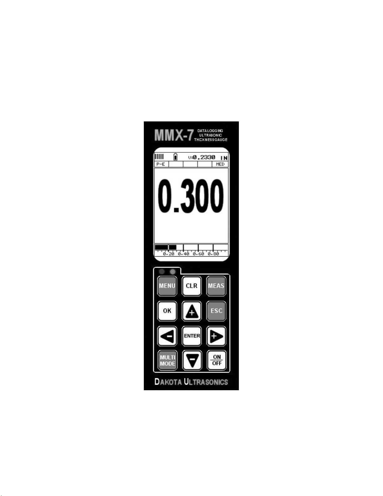
2.1 MMX-7 Overview
In order to understand how to operate the MMX-7, it’s best to start off with an
understanding of what it is we’re looking at exactly. The MMX-7 has a lot of great
features and tools that will prove to be a huge benefit for the variety of applications
you’re constantly facing on a continual basis. Let’s have a brief look at the screens
you’ll be looking at most often:
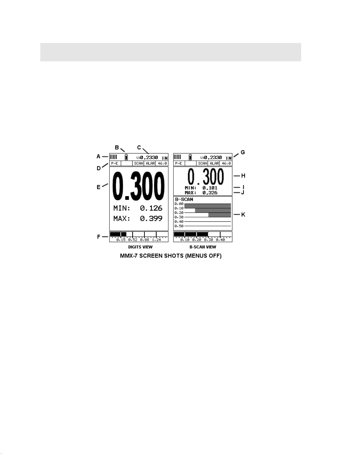
A. Repeatability/Stability Indicator – This indicator should be commonly used
in conjunction with the digital thickness values displayed. When all the vertical
bars are fully illuminated and the last digit on the digital thickness value is
stable, the MMX-7 is reliably measuring the same value 250 times per second
(250 Hz).
B. Battery Icon – Indicates the amount of battery life the MMX-7 has remaining.
C. Velocity – The material velocity value the MMX-7 is currently using or
calibrated for. Displayed in both English or Metric units, depending on what
units the gauge is set for.
2
Page 9

MMX-7 Ultrasonic Thickness Gauge
D. Feature Status Bar – Indicates the features currently enabled and in use in
the following order:
Measurement Mode
Differential Mode
High Speed Scan Mode
Alarm Mode
Gain Setting
E. Digital Material Thickness Value – Extra large font size for viewing ease.
F. Scan Bar – Another view of material thickness in a deflection style horizontal
bar. This is a visual tool that would enable the user the ability to see thickness
changes during high speed scans from flaws and pits.
G. Units – The current measurement units being used (English, Metric).
H. Digital Material Thickness Value – Smaller font size when the B-Scan
display view is enabled.
I. Minimum Material Thickness – Part of the scan feature. Displays the
minimum thickness value found during a scan.
J. Maximum Material Thickness – Part of the scan feature. Displays the
maximum thickness value found during a scan.
K. B-Scan Display – Cross section view of the material. Provides the user with
graphical view of the opposite/blind surface (i.e. inside pipe wall surface), to
give the user some idea of the condition, or integrity of the material being
tested.
3
Page 10
Dakota Ultrasonics
2.2 Selecting the Transducer Type
The MMX-7 is equipped with a transducer list of all of the dual element transducer
options that can be connected to the gauge. These are dual element transducers
with different diameters and frequencies, depending on the material and application
requirements. Transducers with an HD (high damped) designation are commonly
used in conjunction with E-E (echo-echo) through paint modes, while CPZT
(composite) are used for additional output with materials that are difficult to pass
sound through. Finally, the majority of the transducers listed in the table are standard
diameter/frequency transducers used in P-E (pulse-echo) mode. By selecting the
transducer type from a predefined list, the MMX-7 can recall specific properties about
the transducer.
Note: Once the transducer has been selected, the MMX-7 will store and recall this
transducer type every time the MMX-7 is powered on/off. The type will only change if
the user physically selects another transducer type from the list, or selects a
previously saved setup. You’ll notice that the probe type previously selected will be
highlighted every time the probe type screen is displayed.
Use the following steps to select your transducer type:
Selecting the Transducer Type
1) Press the MENU key once to activate the menu items tab. Press the MENU
key multiple times to tab right and the ESC key multiple times to tab left until
the PRB menu is highlighted and displaying the submenu items.
2) Use the UP and DOWN arrow keys to scroll through the sub menu items
until TYPE is highlighted.
4
Page 11
MMX-7 Ultrasonic Thickness Gauge
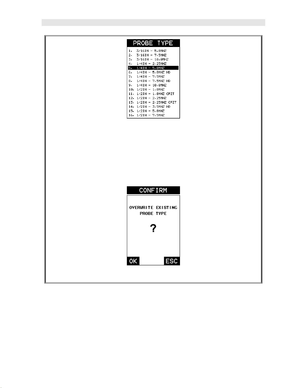
3) Press the ENTER key to display the table/list of transducers.
4) Use the UP and DOWN arrow keys to highlight the transducer type currently
connected to the gauge.
5) Press the ENTER key to load the transducer type and display the
confirmation screen.
6) Press the OK key to overwrite the existing probe type, or ESC to cancel.
2.3 Probe Zero & Calibration
The next steps are to perform a probe zero and calibrate the MMX-7 to the material
and transducer selected. If the sound velocity is unknown, the MMX-7 can be
calibrated to a known thickness sample. The procedures are outlined as follows:
5
Page 12
Dakota Ultrasonics
Performing a Probe Zero
Note: The probe zero disk (battery cap) is located on the top end cap of the
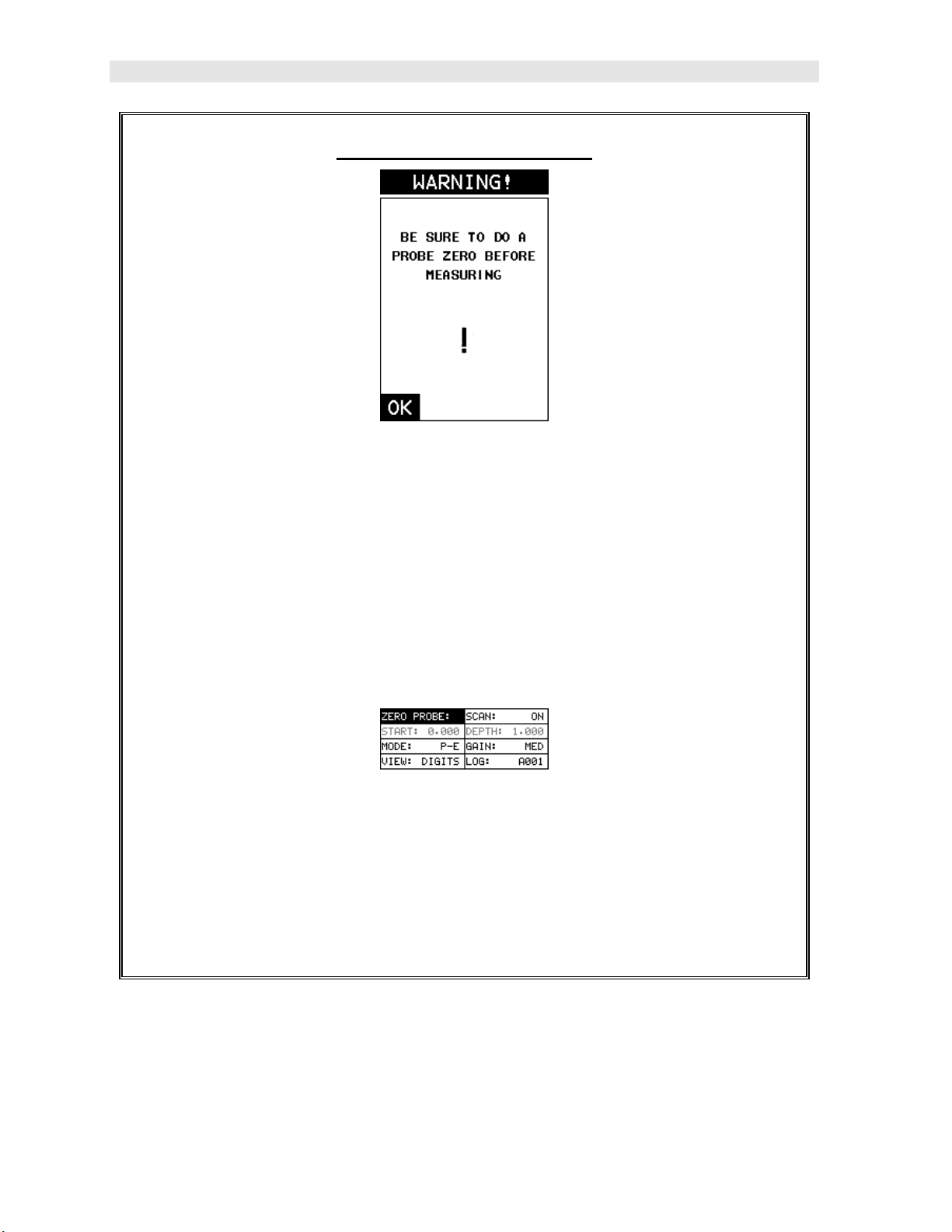
gauge. The warning screen will be displayed following the selection and
overwrite of a new transducer.
1) Press the OK key to enter the main measurement screen and begin the
manual zero process.
2) Apply a drop of couplant on the transducer and place the transducer in
steady contact with the probe zero disk.
3) With the “zero probe” hot menu cell highlighted by default, press the ENTER
key to display the confirmation screen, followed by pressing the OK key to
perform the zero.
Note: If the “zero probe” cell is not highlighted, press the MEAS or ESC keys
to highlight.
6
Page 13
MMX-7 Ultrasonic Thickness Gauge
4) Alternatively, press the MENU key once to activate the menu items tab.
Press the MENU key multiple times to tab right and the ESC key multiple
times to tab left until the PRB menu is highlighted and displaying the
submenu items.
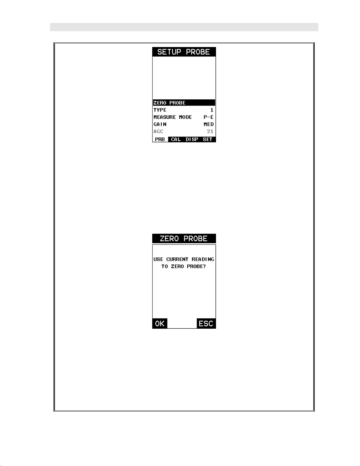
5) Press the UP and DOWN arrow keys to scroll through the sub menu items
until ZERO PROBE is highlighted.
6) Press the ENTER key to display the confirmation screen.
7) Press the OK key to complete the probe zero process, or ESC key to cancel
zeroing.
8) Remove the transducer from the probe zero disk, and proceed to the
calibration section.
7
Page 14
Dakota Ultrasonics
Note: The value that is displayed will change depending on the current velocity
setting in the MMX-7. Disregard the number that is displayed. It is not
important. What is important is accurately performing the steps outlined above
to insure reliability of the probe zero calculation.
One Point Material Calibration
For the purposes of this quick start section, the most common single point calibration
option will covered in this section.
Note: It would be very handy to carry a set of mechanical calipers to use in
conjunction with the MMX-7 for calibration in the field.
Known Thickness
Note: Be sure a probe zero has been performed prior to calibration.
1) Physically measure an exact sample of the material, or a specific location
directly on the material using a set of calipers or a digital micrometer.
2) Apply a drop of couplant on the transducer and place the transducer in
steady contact with the sample or actual test material measured. Be sure
the measurement is stable and the repeatability indicator, in the top left
corner of the display, is fully lit and stable. Press the MENU key once to
8
Page 15
MMX-7 Ultrasonic Thickness Gauge
activate the menu items tab. Press the MENU key multiple times to tab right
and the ESC key multiple times to tab left until the CAL menu is highlighted
and displaying the submenu items.
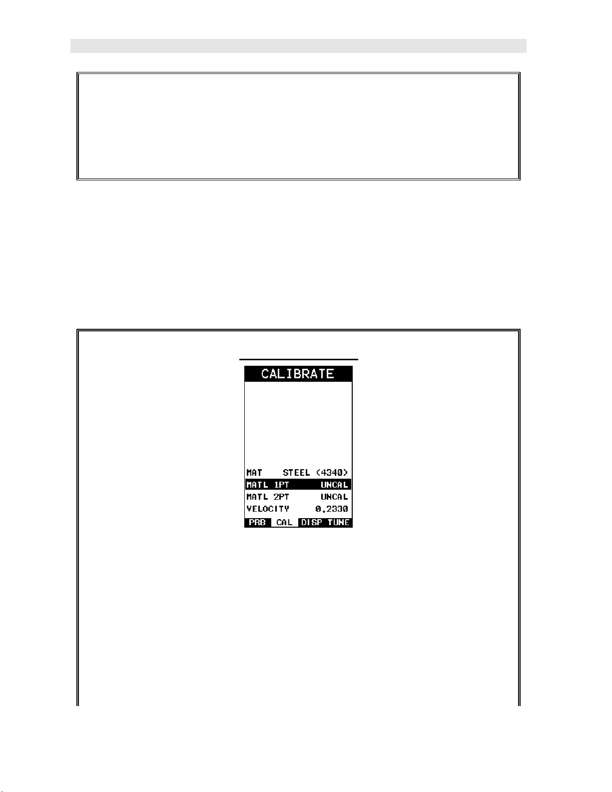
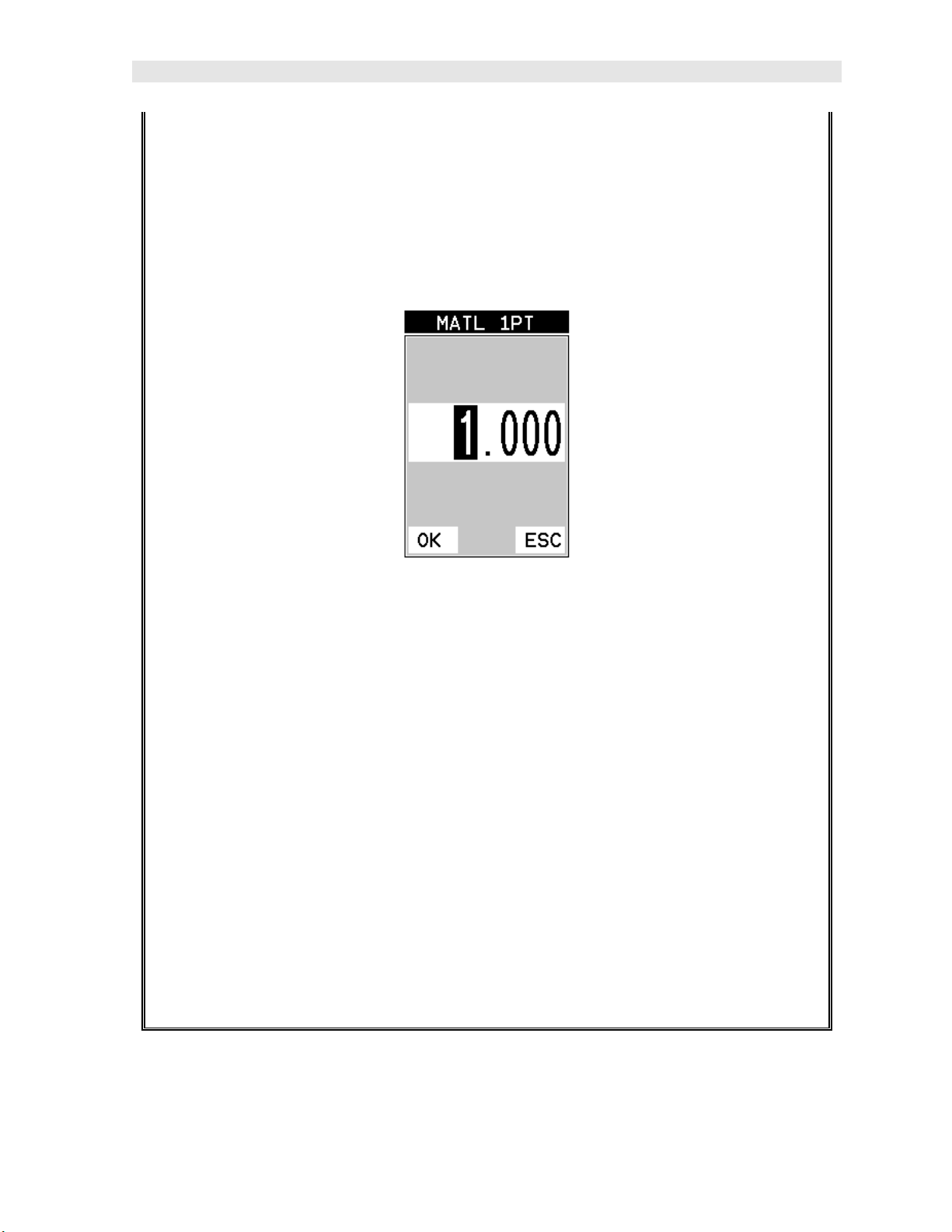
3) Use the UP and DOWN arrow keys to scroll through the sub menu items
until MATL 1PT is highlighted.
4) Press the ENTER key to display the Digits Edit Box.
5) Press the UP and DOWN arrow keys to scroll the highlighted value.
6) Press the LEFT and RIGHT arrow keys to scroll the digit locations.
7) Repeat steps 5 & 6 until the known thickness value is correctly displayed.
8) Press the OK key to calculate the velocity and return to the menu screen, or
ESC to cancel the one point calibration.
9) Finally, press the MEAS key to return to the measurement screen and begin
taking readings.
Note: CHECK YOUR CALIBRATION! Place the transducer back on the
calibration point. The thickness reading should now match the known
thickness. If the thickness is not correct, repeat the steps above.
9
Page 16
Dakota Ultrasonics
2.4 Measure
The MMX-7 is now ready to measure. There are two different measurement view
options each with a specific purpose – Digits & B-Scan. The steps below outline how
to toggle between the different view mode options:
Selecting the Measurement View Option
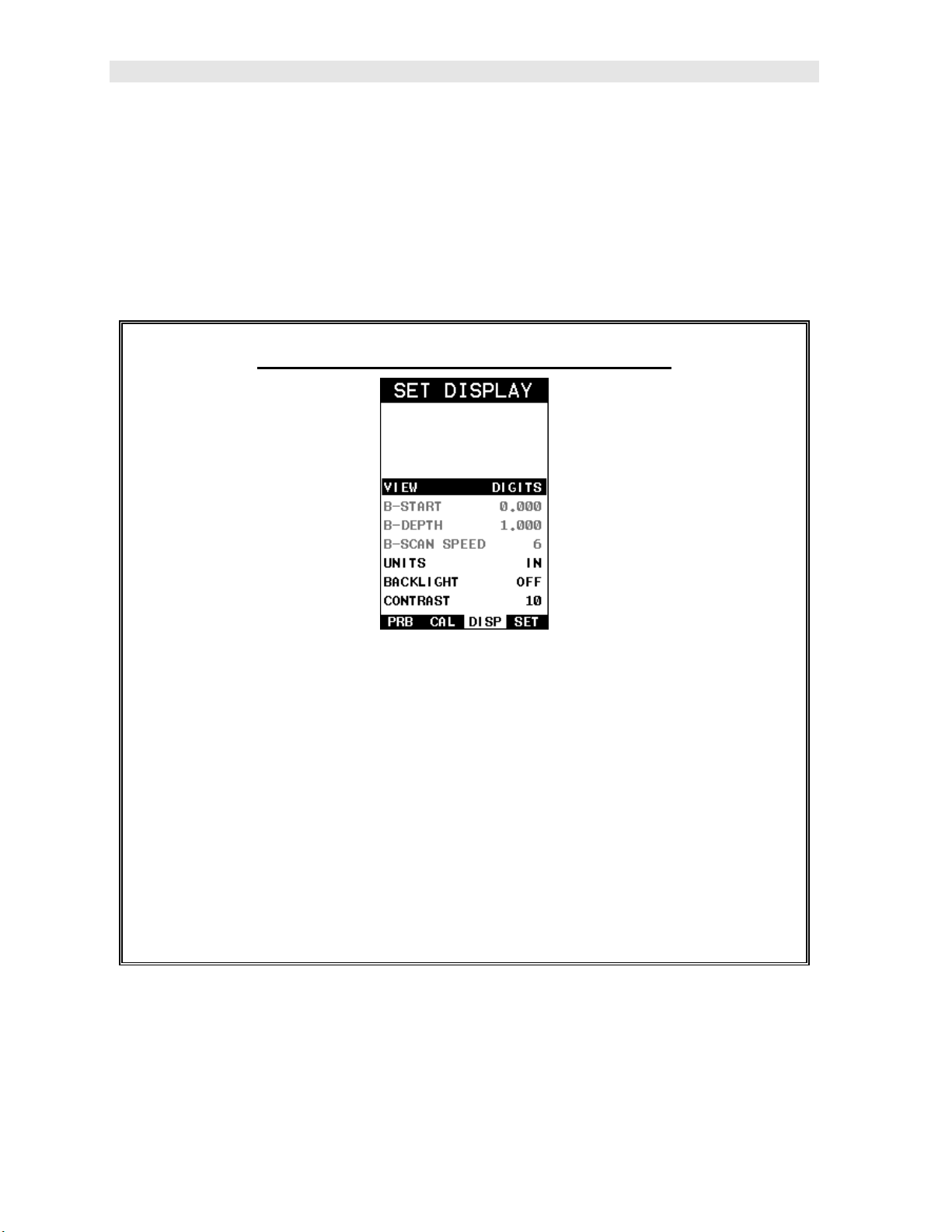
1) Press the MENU key once to activate the menu items tab. Press the MENU
key multiple times to tab right and the ESC key multiple times to tab left until
the DISP menu is highlighted and displaying the submenu items.
2) Use the UP and DOWN arrow keys to scroll through the sub menu items
until VIEW is highlighted.
3) Use the LEFT and RIGHT arrow keys to scroll the view options.
4) Once the view is displayed, press the MEAS key to return to measurement
mode.
DIGITS: Displays the digital thickness value using a large font size. This view is
useful when the MMX-7 is being used as a basic thickness gauge.
BSCAN: The Time Based B-Scan provides the user with a cross sectional view of
the material being tested. This mode is useful when there is concern regarding the
10
Page 17
MMX-7 Ultrasonic Thickness Gauge
profile of the blind surface. This can also be a useful view when scanning for pits and
flaws.
Once the view has been selected according to the application requirements, the B-
Scan Start (B-ST) and Depth (B-DEP) will potentially need adjustment in order to
optimize the zoom if the MMX-7 has been set to B-Scan.
Use the following steps to adjust these settings directly from the measurement
screen as follows:
Note: The B-Start and B-Depth are also used to adjust the parameters of Scan
Bar.
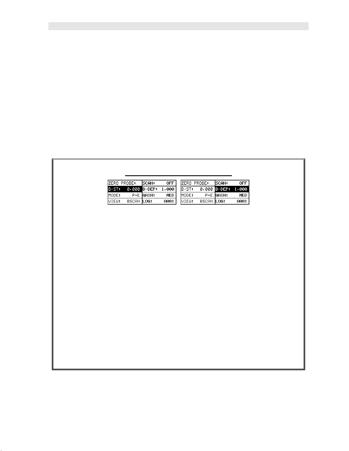
Adjusting B-Start & B-Depth
1) Press the MEAS key once to activate the measure menu items. Press the
MEAS key multiple times to move right and the ESC key multiple times to
move left, until the either the B-ST or B-DEP cell is highlighted.
2) Use the UP, DOWN, LEFT, or RIGHT arrow keys to scroll the B-ST and B-
DEP values.
3) Repeat steps 1 & 2 until the range is correctly being displayed.
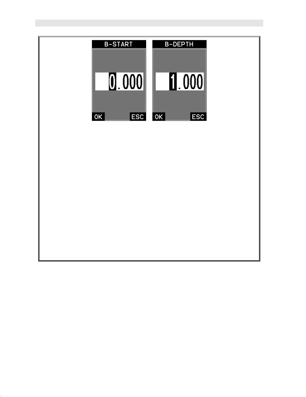
Alternatively, the B-ST and B-DEP values can be changed using the Digit Edit
Box as follows:
1) Press the MEAS key once to activate measure menu items. Press the
MEAS key multiple times to move right and the ESC key multiple times to
move left, until the either the B-ST or B-DEP cell is highlighted.
11
Page 18
Dakota Ultrasonics
2) Press the ENTER key to display the digits edit box.
3) Press the UP and DOWN arrow keys to scroll the highlighted value.
4) Press the LEFT and RIGHT arrow keys to scroll the digit locations.
5) Repeat steps 3 & 4 until the B-ST or B-DEP value is correctly displayed.
6) Press the OK key to set the B-ST and B-DEP value and return to the
measure screen, or ESC to cancel entering the B-ST or B-DEP value.
7) Finally, press the MEAS key to return to the measurement screen and begin
taking readings.
Note: The B-START & B-DEPTH can also be adjusted from the tabbed menu
item DISP. However, using the hot menu keys is the most convenient method.
12
Page 19
CHAPTER THREE
KEYBOARD, MENU, & CONNECTOR REFERENCE
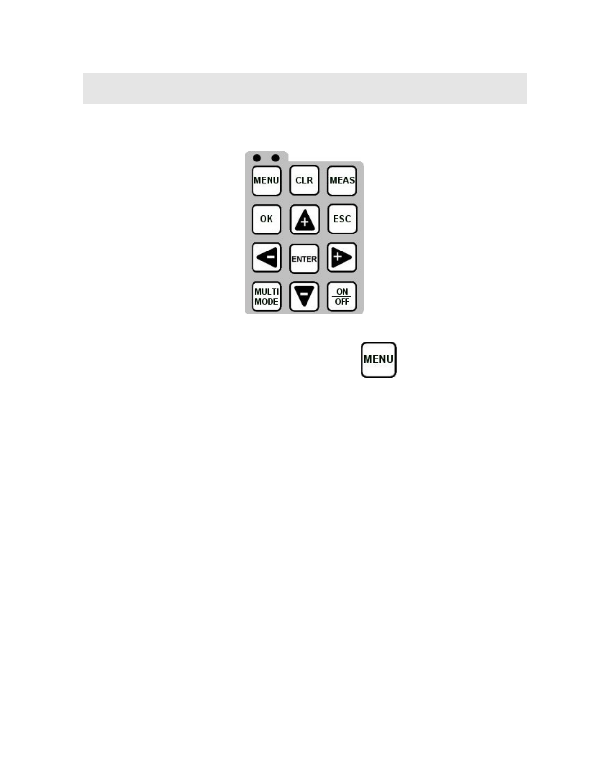
3.1 Menu Key (Operation & Sub Menus)
The Menu key activates the primary menu structure containing 8 menu tab groups.
These tab groups then contain sub menu items, or functions. The sub menu items
have been organized in tab groups according to how closely they are related to the
individual tab group names. Let’s first get familiar with how to move around in these
tabs before continuing on to the sub menu functions. This procedure is outlined
below:
13
Page 20
Dakota Ultrasonics
Activating and Getting Around in the Menu Items
1) Press the MENU key once to activate the menu items tab. Press the MENU
key multiple times to tab right, and the ESC key multiple times to tab left
until the desired tab group is highlighted and displaying the submenu items.
The tab groups are illustrated above (A).
Now that you’re familiar with activating and moving amongst the tab groups, let’s
have a look at how to move around in the sub menu items as follows:
Getting Around in the Sub Menu Items
1) Use the UP and DOWN arrow keys to scroll through the sub menu items
until the desired function is highlighted. The sub menu items are illustrated
in the diagram above (B).
2) Depending on which function is highlighted, use the LEFT, RIGHT, and
Enter keys to scroll the options or activate the Digit Edit and List Box
options.
The sections to follow will provide the user with an explanation of the sub menu
functions:
14
Page 21
MMX-7 A/B Scan Thickness Gauge
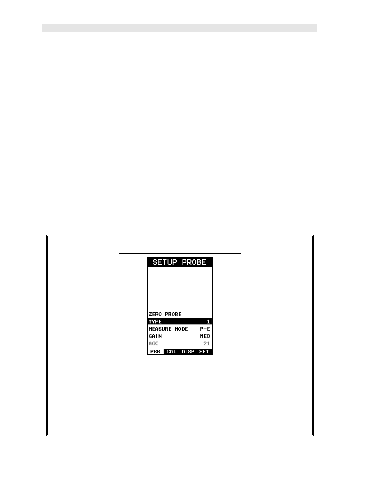
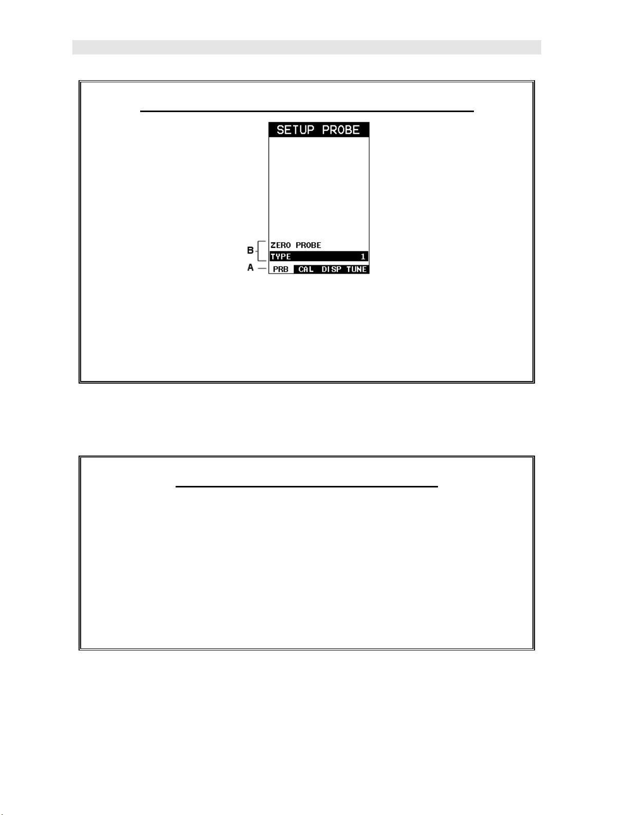
3.2 Probe – Menu
ZERO PROBE: The MMX-7 is zeroed in much the same way that a mechanical
micrometer is zeroed. If the MMX-7 is not zeroed correctly, all of the measurements
made using the MMX-7 may be in error by some fixed value. The MMX-7 is
equipped with an optional automatic or manual zero feature. Refer to the section on
page 30, for an explanation of this important procedure.
TYPE: Enables the user to select the type of transducer being used from a chart of
transducer types. This provides increased linearity between transducers. Refer to
page 4 for a further explanation.
MEASURE MODE: Toggles between the measurement modes; pulse-echo (P-E) and
echo-echo (E-E). Refer to page 23 for further info.
GAIN: Active only if the measure mode is set to pulse-echo (P-E), and is used to
increase/decrease the overall amplitude of the signal. The gain can be adjusted
using a three position switch with LOW, MED, HI settings. MED is set to 46 dB, with
a 3 dB cut or boost. Consider it as similar to turning the volume up or down on a
stereo receiver. Refer to page 48 for further info.
AGC: Active only if the measure mode is set to echo-echo (E-E), and is used to
increase/decrease the over amplitude of the signal. The gain can be adjusted using
a three position switch with LOW, MED, HI settings. The AGC target is defined as
MED, with a 3 dB cut/boost. Refer to page 48 for further info.
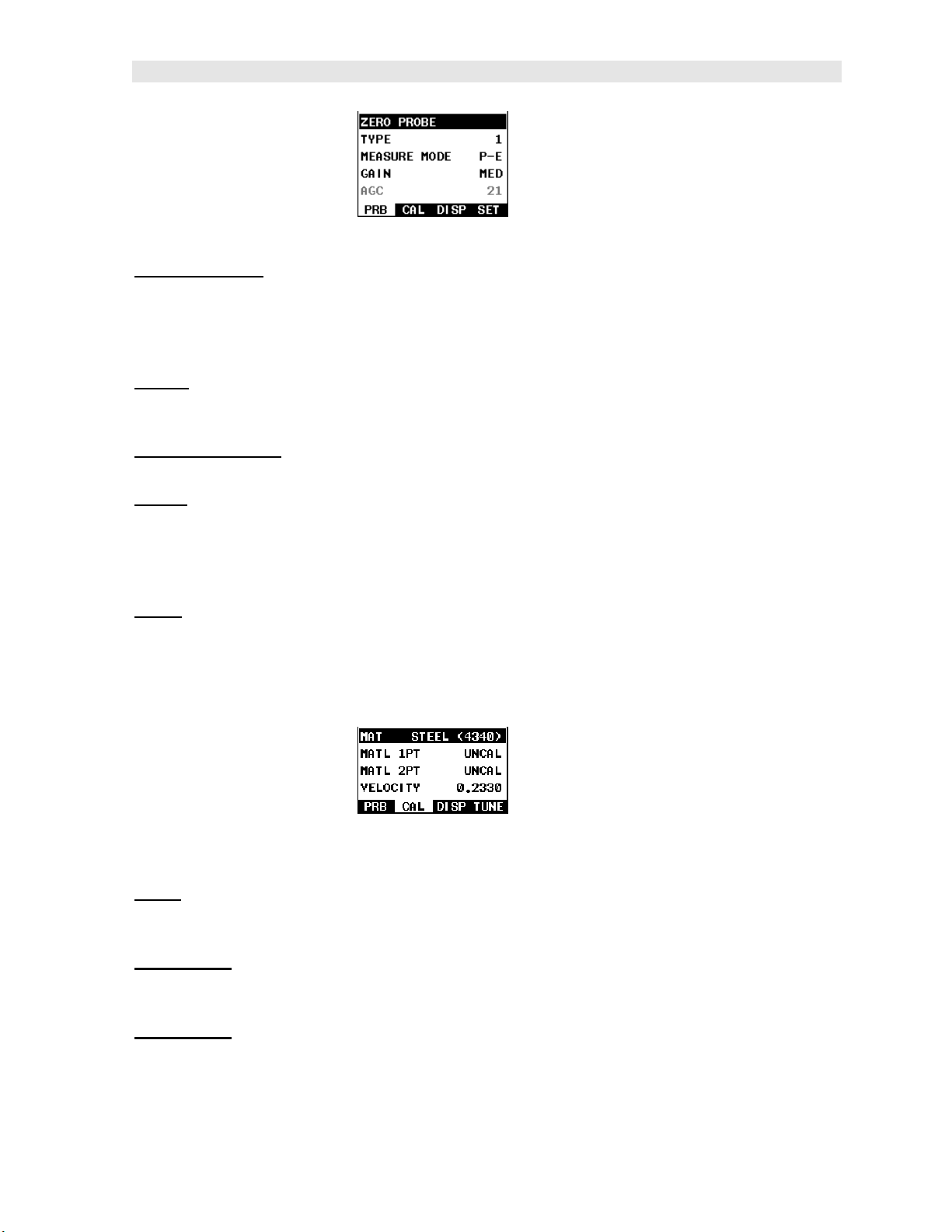
3.3 CAL – Menu
MAT:
Select the material velocity from a chart of basic material types when a known
sample thickness, or material velocity cannot be obtained. Refer to page 38 for
further info.
MATL 1PT:
automatically calculate the velocity by entering a known sample thickness. Refer to
page 35 for further info.
MATL 2PT: Performs a two-point calibration. This option allows the user to
automatically calculate the velocity by entering a second known sample thickness.
Refer to page 37 for further info.
Performs a single point calibration. This option allows the user to
15
Page 22
Dakota Ultrasonics
VELOCITY: Function to calibrate the MMX-7 by setting the velocity to a known
material velocity. Refer to page 32 for further info.
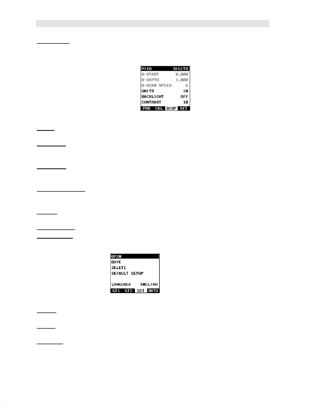
3.4 DISP (display) – Menu
VIEW:
page 42 for further info.
B-START:
view. Adjusts the range of the scan bar in digits view. Refer to page 43 for further
info.
B-DEPTH: Provides the user the ability to change the overall depth of the viewable
measurement area. Adjusts the range of the scan bar in digits view. Refer to page
46 for further info.
B-SCAN SPEED: Controls the speed of the time based B-Scan with an arbitrary
scale of 0-10, with 10 being the fastest scrolling speed. Default speed set at 6.
Refer to page 46 for further info.
UNITS: Toggle between English or Metric units. The readout will change from
inches to millimeters (0.001” / 0.01mm).
BACKLIGHT: Selectable OFF, ON, AUTO, or INVERT backlight option.
CONTRAST: Adjustable display contrast for variable light conditions.
Selectable BSCAN (cross section), and DIGITS (large digits) views. Refer to
Provides the user the ability to change the start position of the B-SCAN
3.5 SETUP – Menu
OPEN:
These setups can be recalled and used at any time. Refer to page 84 for further info.
SAVE: Provides the user with the ability to save a custom setup that has been
modified or created by the user. Refer to page 86 for further info.
DELETE: Provides the user with the ability to delete specific setups previously save
in memory. Refer to page 90 for further info.
Displays a list of factory and user defined setups currently stored in memory.
16
Page 23
MMX-7 A/B Scan Thickness Gauge
DEFAULT SETUP: Loads a basic default setup. Use only as a last resort when the
setups in the MMX-7 have been corrupted and a computer is not accessible. Refer to
page 92 for further info.
LANGUAGE: Provides the user the ability to select different languages for the MMX-
7. Refer to page 93 for further info.
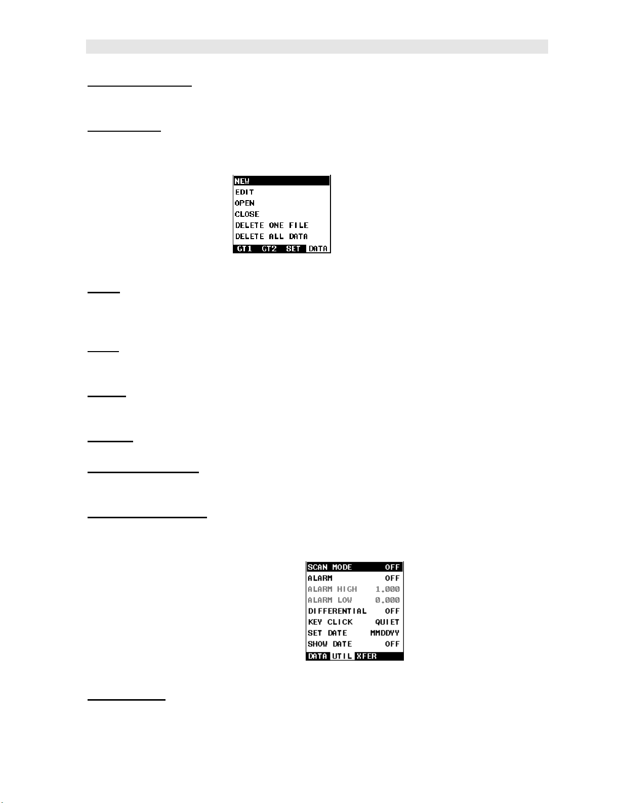
3.6 DATA – Menu
NEW:
log file with auto identifiers. It is equipped with custom parameters, rows, and
columns depending on the user’s application reporting requirements. Refer to page
63 for further info.
EDIT: Gives the user the ability to change parameters of grid or sequential file
previously saved. Note: Pre-defined coordinates cannot be changed once they have
been created. Refer to page 77 for further info.
OPEN: This function provides the user with the ability to recall grids or sequential log
files that currently exist in memory, from a list of grids. Refer to page 79 for further
info.
CLOSE: Provides the user the ability to close a currently opened grid or sequential
log file. Refer to page 81 for further info.
DELETE ONE FILE: This function provides the user with the ability to delete one
individual grid or sequential log file from a list of multiple grids/files previously saved
in memory. Refer to page 74 for further info.
DELETE ALL DATA: This function provides the user with the ability to delete all files
currently stored in memory. Refer to page 75 for further info.
Allows the user the ability to create a new alpha numeric grid, or sequential
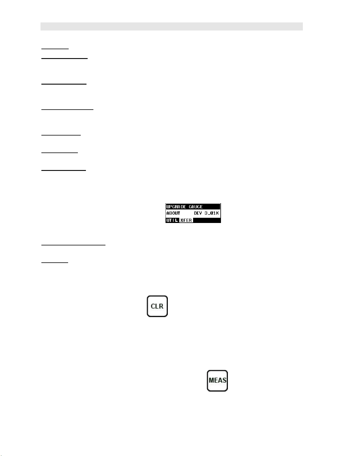
3.7 UTIL (utilities) – Menu
SCAN MODE:
overall sample rate from 65 to 200 measurements per second, depending on the
current measurement mode used. Refer to page 52 for further info.
This function enables a high speed scan mode that increases the
17
Page 24
Dakota Ultrasonics
ALARM: Toggles alarm mode on, off, or audible. Refer to page 53 for further info.
ALARM HIGH: Gives the user the ability to set the HI limit parameter. If the
measurement exceeds this value, a red light will illuminate and sound the internal
beeper. Refer to page 53 for further info.
ALARM LOW:
measurement falls below this value, a red light will illuminate and sound the internal
beeper. Refer to page 53 for further info.
DIFFERENTIAL:
will display +/- the difference from the nominal value entered. Refer to page 55 for
further info.
KEY CLICK: Give the user the ability to set the level of the key press beeper, OFF,
QUIET, or LOUD. Refer to page 56 for further info.
SET DATE: Gives the user the ability to set the internal date and time stamp in the
MMX-7. Refer to page 57 for further info.
SHOW DATE: Gives the user the ability to display the date and time in the waveform
area of the MMX-7. The options are OFF, DATE, TIME, BOTH. Refer to page 59 for
further info.
Gives the user the ability to set the LO limit parameter. If the
Gives the user the ability to set a nominal value and the MMX-7
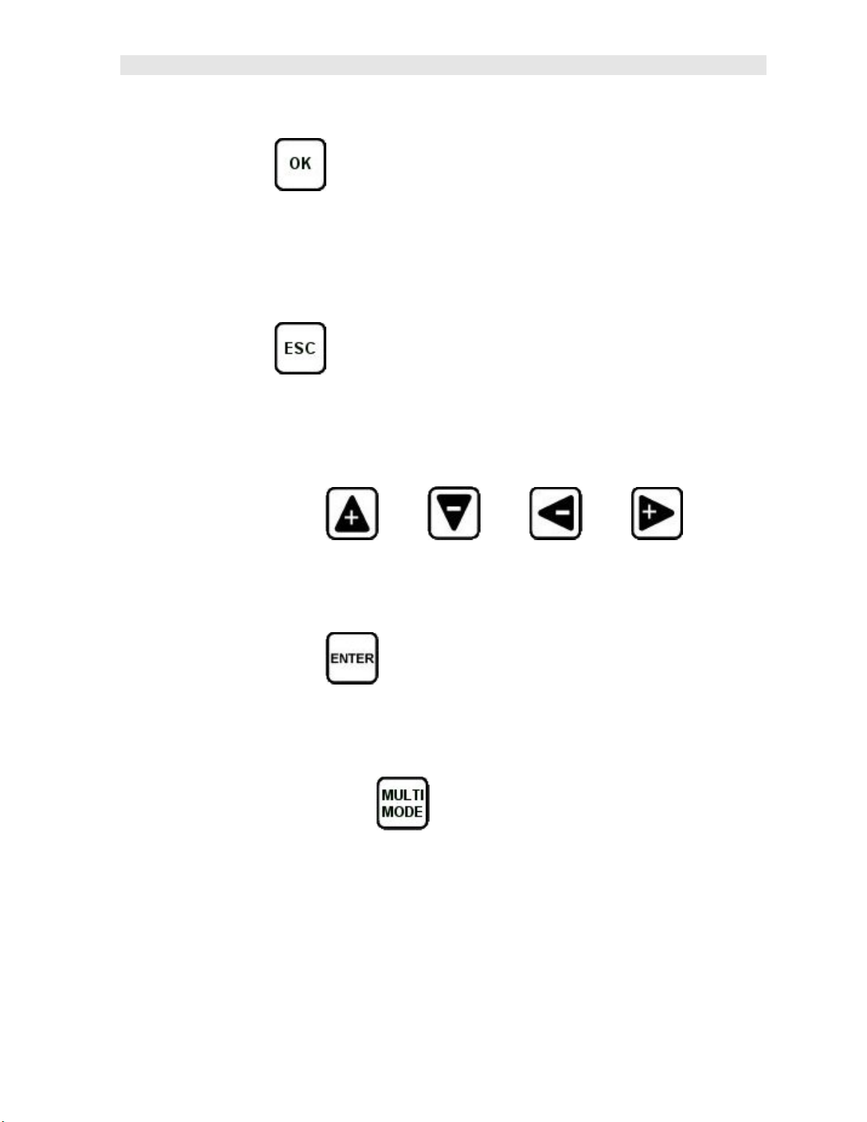
3.8 XFER (transfer) – Menu
UPGRADE GAUGE: Enables the user the ability to upgrade the MMX-7 to the most
current firmware revision. Latest version posted on www.dakotaultrasonics.com.
ABOUT: Provides the user with Dakota Ultrasonics contact information and the
MMX-7 firmware version. Refer to the Dakota Ultrasonics web site for information on
the latest firmware versions available for download.
3.9 CLR (clear) Key
The primary functions of the CLR key is to clear a measurement from a grid file cell
location, set an obstruct, or backspace in an Alpha Edit Box. If a user has already
saved a measurement and B-Scan to a cell location, use this key to clear the
measurement at any time.
3.10 MEAS (measurement mode) Key
The MEAS key returns the MMX-7 to the primary measurement screen/view. Press
at any time to view the main screen.
18
Page 25
MMX-7 A/B Scan Thickness Gauge
3.11 OK Key
The primary function of the OK key is confirmation of a change or selection.
Additionally, the OK key also toggles the Hot Menu area to a large digits display
while in measurement mode. If the MMX-7 is displaying a grid log, the OK key
toggles an advance to row number option.
3.12 ESC Key
The ESC key is used in the MENU, MEAS, and EDIT functions as a back or escape
function. If the MMX-7 is displaying a grid or sequential log, the ESC key toggles the
display options: Digits or B-Scan views.
3.13 Arrow Keys
The Arrow Keys are used to navigate through the menus, increase/decrease values,
and toggle specific function keys.
3.14 ENTER key
The ENTER key is used in the overall menu selection process, to activate list and
edit boxes, display and save measurements to grid file location.
3.15 MULTI MODE Key
The MULTI MODE key opens a measurement mode screen that lists all the modes
available for the transducer selected. The two modes available are pulse-echo (P-E)
and echo-echo (E-E). The high damped transducers will offer both modes, while the
majority will only offer pulse-echo. An additional menu item “capture To File” is also
available when pressing the MULTIMODE key. This allows a user to capture a
screenshot of any measurement screen, menu, or list to a .tif file stored on the
internal SD card.
19
Page 26

Dakota Ultrasonics
3.16 ON/OFF Key
The ON/OFF key simply powers the unit either ON or OFF.
Note: Unit will automatically power off when idle for 5 minutes. All current settings
are automatically saved prior to powering off.
20
Page 27
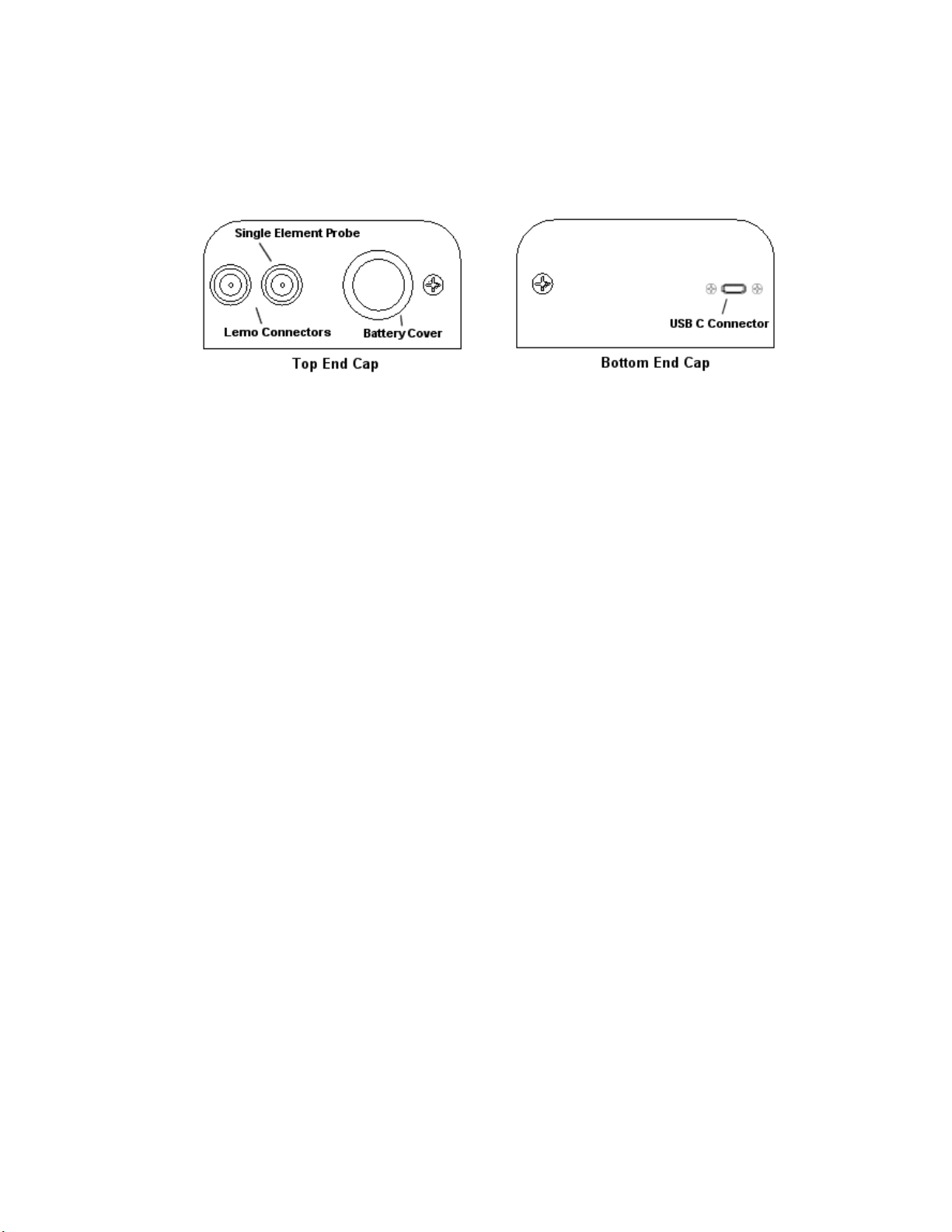
3.17 Top & Bottom End Caps
The top & bottom end panels are where all connections are made to the MMX-7. The
diagram above shows the layout and description of the connectors:
Transducer Connectors
Refer to Diagram: The transducer connectors and battery cover/probe zero disk are
located on the MMX-7 top end cap. The transducer connectors are of type Lemo
“00”.
Note: There is no polarity associated with connecting the transducer to the MMX-7.
Probe Zero Disk & Battery Cover
Refer to Diagram: The Battery cover is the large round disk shown in the diagram.
Note: This same disk is also used as a probe zero disk. Simply remove the cover
when replacing the batteries (3 AA cells). When performing a manual probe zero
function, simply place the transducer on disk making firm contact. Important: Be
sure to follow the polarity labels located on the back label of the MMX-7.
Note: Rechargeable batteries can be used however they must be recharged outside
of the unit in a stand-alone battery charger.
USB-C Connector
Refer to Diagram: The USB-C connector, located on the bottom end cap, is a mini
type C female connector. It is designed to connect directly from the MMX-7 to a
standard USB type A port on a PC. The cable supplied with the MMX-7 is a USB
type C to a USB type A (pt# N-003-0330).
Note: This connector is also used to upgrade the MMX-7 with the latest version of
firmware.
21
Page 28

CHAPTER FOUR
PRINCIPALS OF ULTRASONIC MEASUREMENT
4.1 Time versus thickness relationship
Ultrasonic thickness measurements depend on measuring the length of time it takes
for sound to travel through the material being tested. The ratio of the thickness
versus the time is known as the sound velocity. In order to make accurate
measurements, a sound velocity must be determined and entered into the
instrument.
The accuracy of a thickness measurement therefore depends on having a consistent
sound velocity. Some materials are not as consistent as others and accuracy will be
marginal. For example, some cast materials are very granular and porous and as a
result have inconsistent sound velocities.
While there are many different ultrasonic techniques to measure thickness, which will
be discussed below, all of them rely on using the sound velocity to convert from time
to thickness.
4.2 Suitability of materials
Ultrasonic thickness measurements rely on passing a sound wave through the
material being measured. Not all materials are good at transmitting sound.
Ultrasonic thickness measurement is practical in a wide variety of materials including
metals, plastics, and glass. Materials that are difficult include some cast materials,
concrete, wood, fiberglass, and some rubber.
4.3 Range of measurement and accuracy
The overall measurement capabilities, based on the wide variety of materials, is
determined by the consistency of the material being measured
The range of thickness that can be measured ultrasonically depends on the material
as well as the technique being used and the type of transducer. Thickness
measurements can be made from a minimum of 0.010 inch to 9.999” in steel.
However, the maximum attainable thickness is much less for more attenuative
materials (materials that absorb sound).
Accuracy, is determined by how consistent the sound velocity is through the sound
path being measured, and is a function of the overall thickness of the material. For
example, the velocity in steel is typically within 0.5% while the velocity in cast iron
can vary by 4%.
4.4 Couplant
All ultrasonic applications require some medium to couple the sound from the
transducer to the test piece. Typically a high viscosity liquid is used as the medium.
The sound frequencies used in ultrasonic thickness measurement do not travel
22
Page 29

MMX-7 A/B Scan Thickness Gauge
through air efficiently. By using a liquid couplant between the transducer and test
piece the amount of ultrasound entering the test piece is much greater.
4.5 Temperature
Temperature has an effect on sound velocity. The higher the temperature, the slower
sound travels in a material. High temperatures can also damage transducers and
present a problem for various liquid couplants.
Since the sound velocity varies with temperature it is important to calibrate at the
same temperature as the material being measured.
Normal temperature range
Most standard transducers will operate from 0F to 180F.
High temperature measurements
Special transducers and couplants are available for temperatures above 180F up to
650F with intermittent contact. It is necessary to cool the transducer, by submerging
the transducer in water between readings, when measuring high temperatures.
Modes and temperature errors
In addition to errors caused by velocity changing with temperature, some modes
(measurement techniques) are affected more than others. For example, dual
element pulse-echo mode has larger errors due to changes in the temperature of the
delay line. However, multi-echo techniques offer temperature compensation help to
minimize these errors.
4.6 Measurement Modes
In this section we will discuss the different measurements modes the MMX-7 is
capable of operating in, the transducers required, and the reasons for using specific
modes:
Pulse-Echo Mode (Flaw & Pit detection) – (P-E)
Pulse-echo mode measures from the initial pulse (sometimes referred to as an
artificial zero) to the first echo (reflection). A manual probe zero can be performed
while in this mode by placing the transducer on the reference disk located at the top
end cap of the MMX-7 and selecting the ‘zero transducer’ option in the “PRB” menu,
or the ‘zero probe’ option in the hot menu items.
Errors can result from surface coatings and temperature gradients in pulse-echo
mode. Therefore, the zero process should be performed on a frequent basis.
This mode is commonly used to detect flaws and pits, as it only requires one
reflection and adjustable gate to improve sensitivity when measuring heavily
corroded metals.
23
Page 30

Dakota Ultrasonics
V-Path Correction
Dual element delay line transducers have two piezoelectric elements mounted at an
angle on one end of the delay line. One element is used for transmitting sound, while
the other element only receives sound. The two elements and their delay lines are
packaged in a single housing but acoustically isolated from each other with a sound
barrier. This allows the transducer the ability to achieve very high sensitivity for
detecting small defects. Also, the surface of the test material does not have to be as
flat in order to obtain good measurements.
Dual element transducers are normally used in pulse-echo mode for finding defects,
and in echo-echo mode for through coating measurements.
Dual element delay line transducers are usable over a range of 0.025 inches to 20
inches depending on the material, frequency, and diameter.
A limitation of dual element delay-line transducers is the V shaped sound path.
Because the sound travels from one element to another, the time versus thickness
relationship is non-linear. Therefore, a correction table in the instruments software is
used to compensate for this error.
Dual Element Transducer showing V-path of signal
Searching for small defects
Dual element delay line transducers are especially useful in searching for small
defects. In the pulse-echo mode with high amplifier gain, very small defects can be
measured, and is useful during corrosion inspections to locate pits, porosity and
cracks during tank and pipeline inspections, for example.
Echo-Echo Mode – Thru Coat (E-E)
The echo-echo mode measures between two reflections. This technique is
commonly used to eliminate errors from surface coatings and applications with
temperature gradients. The disadvantage is that two echoes are required for
measurement. Certain materials can be difficult to pass sound through, making it
hard to successfully achieve multiple echoes.
24
Page 31

MMX-7 A/B Scan Thickness Gauge
Dual Element Transducer in Echo to Echo mode
25
Page 32

CHAPTER FIVE
SELECTING THE MEASUREMENT MODE
5.1 The setup library
The MMX-7 contains 64 user configurable preset locations to store custom setups for
easy recall. These setups can be optimized for common application requirements,
and bi-directionally transferred to the gauge and computer using Dakota’s PC or OSX
interface software, included with the instrument.
5.2 Which mode & transducer do I use for my application?
High penetration plastics and castings
The most common mode for these types of applications is pulse-echo. The MMX-7
has been optimized for cast materials. Cast iron applications require 1 - 5MHz
frequencies, and cast aluminum requires a 10MHz frequency. Plastics typically
require lower frequencies depending on the thickness and make-up of the material.
Larger diameters offer greater penetration power because of the crystal size, for
difficult to measure materials.
Corrosion & Pit Detection in steel and cast materials
Use pulse-echo mode whenever attempting to locate pits and flaws. Typically a
5MHz transducer, or higher, will be used for these types of applications. Use low
frequencies for greater penetration and use higher frequencies for better resolution.
Thru Paint & Coatings
Often times, users will be faced with applications where the material will be coated
with paint or some other type of epoxy material. Since the velocity of the coating is
approximately 2.5 times slower than that of steel, pulse-echo mode will induce error if
the coating or paint is not completely removed. By using echo-echo mode, the user
is able to successfully measure through both, the coating and steel, and completely
eliminate the thickness of the paint or coating. Therefore, the steel can be measured
without having to remove the coating prior to measuring. Users will often use pulseecho mode and echo-echo mode in conjunction when performing inspections on
coated materials.
Thru coating measurements require special high damped transducers. The most
common transducers are the 3.5, 5, and 7.5MHz hi damped transducers. These
transducers are suitable for use in both pulse-echo and echo-echo modes. This
conveniently enables the user to accurately measure overall material thickness using
the thru Coating mode, and then conveniently switch to pit detection mode without
changing transducers.
26
Page 33

MMX-7 A/B Scan Thickness Gauge
Thin materials
Use pulse echo mode and a high frequency transducer for these types of
applications. The most common transducers are the 7.5MHz and 10MHz models
with extra resolution. The higher frequencies provide greater resolution and a lower
minimum thickness rating overall.
High temperature
Use and select a special 2.25MHz and 5 MHz High temperature transducer for these
types of applications. Both pulse-echo and echo-echo modes will also work for these
applications. However, echo-echo mode will eliminate error caused by temperature
variations in the delay line of the transducer.
Noisy Material
Materials such as titanium, stainless steel, and aluminum may have inherent surface
noise issues. This is a signal that appears at the surface of the material when using
a dual element delay line probe. Select a higher frequency transducer to reduce this
noise – 7.5MHz and higher for better resolution.
Restricted access
Measuring materials with extreme curvatures or restricted access, higher frequencies
with smaller diameters should be considered. The smallest diameter uses 3/16”
crystals with a contact area of .250”. Custom transducers are available on request.
5.3 Factory Setup Chart
Num Name Comment 1 Gn/AGC Velocity
1 Enter Custom Name
2 …
3 …
4 …
5 …
6 …
… …
27
Page 34

CHAPTER SIX
MAKING MEASUREMENTS
6.1 Selecting the Transducer Type
The first step in using the MMX-7 is to plug the transducer into the gauge and power
up the unit to display the main measurement screen. The diameter and frequency
should be noted in order to select a transducer from the list of probes in the gauge.
The steps to select a transducer are outlined below:
Note: Once the transducer has been selected, the MMX-7 will store and recall this
transducer type every time the MMX-7 is powered on/off. The type will only change if
the user physically selects another type from the list, or selects a previously stored
setup. Therefore, if you have previously gone through this section and selected the
transducer you are using, proceed to the next section.
Selecting the Transducer
1) Press the MENU key once to activate the menu items tab. Press the MENU
key multiple times to tab right and the ESC key multiple times to tab left until
the PRB menu is highlighted and displaying the submenu items.
2) Press the UP and DOWN arrow keys to scroll through the sub menu items
until TYPE is highlighted.
28
Page 35

MMX-7 A/B Scan Thickness Gauge
3) Press the ENTER key to display the list of transducer options.
4) Press the UP and DOWN arrow keys to scroll through the transducer list
until the appropriate type is highlighted.
5) Press the ENTER key to select the transducer type and display overwrite
confirmation screen.
6) Press the OK key to overwrite the existing probe type with the newly
selected type.
29
Page 36

Dakota Ultrasonics
7) The zero probe warning screen will be displayed. Press the OK key,
followed by pressing the MEAS key to return to the main measurement
screen and proceed to the probe zero section that follows.
6.2 Probe zero
The next step is to perform a probe zero. This must be done prior to calibration,
and periodically performed during an inspection to account for temperature
variations. If the MMX-7 is not zeroed correctly, all measurements may be in error by
some fixed value. In order to perform a zero, the gauge must be set to pulse-echo
measurement mode. If the MMX-7 is currently set to echo-echo mode, the menu
item “transducer zero” will be grayed out and inactive.
The procedure to perform a zero is outlined below:
Probe Zero
1) Apply a drop of couplant on the transducer and place the transducer in
steady contact with the probe zero disk at the top of the gauge.
30
Page 37

MMX-7 A/B Scan Thickness Gauge
2) With the “zero probe” hot menu cell highlighted by default, press the ENTER
key to display the confirmation screen, followed by pressing the OK key to
perform the zero.
Note: If the “zero probe” cell is not highlighted, press the MEAS or ESC keys
to highlight.
3) Alternatively, press the MENU key once to activate the menu items tab.
Press the MENU key multiple times to tab right and the ESC key multiple
times to tab left until the PRB menu is highlighted and displaying the
submenu items.
4) Press the UP and DOWN arrow keys to scroll through the sub menu items
until ZERO PROBE is highlighted.
5) Press the ENTER key to display the confirmation screen.
31
Page 38

Dakota Ultrasonics
6) Press the OK key to perform the zero, or ESC key to cancel the probe zero
process.
7) Proceed to the calibration section.
Note: The value that is displayed will change depending on the current velocity
setting in the MMX-7. Disregard the number that is displayed. It is not
important. What is important is accurately performing the steps outlined above
to insure reliability of the probe zero calculation.
6.3 Material Calibration
In order for the MMX-7 to make accurate measurements, it must be set to the correct
sound velocity of the material being measured. Sound will travel at different speeds
in different material types. For example, the velocity of sound through steel is about
0.233 inches per microsecond, versus that of aluminum, which is about 0.248 inches
per microsecond. If the gauge is not set to the correct sound velocity, all of the
measurements the gauge makes will be erroneous by some fixed percentage.
The One Point calibration is the simplest and most commonly used calibration
method - optimizing linearity over large ranges. The Two Point calibration allows for
greater accuracy over small ranges by calculating the probe zero and velocity. The
MMX-7 provides four simple methods for setting the sound-velocity outlined below:
Known Velocity
If the material velocity is known, the user may wish to simply enter the velocity
number into the MMX-7, rather than have the MMX-7 calculate the velocity value
using a known thickness on a material sample. The steps for entering the velocity
are outlined below:
Using a Known Material Velocity
32
Page 39

MMX-7 A/B Scan Thickness Gauge
1) Press the MENU key once to activate the menu items tab. Press the MENU
key multiple times to tab right and the ESC key multiple times to tab left until
the CAL menu is highlighted and displaying the submenu items.
2) Use the UP and DOWN arrow keys to scroll through the sub menu items
until VELOCITY is highlighted.
3) Press the ENTER key to display the Digits Edit Box.
4) Press the UP and DOWN arrow keys to scroll the highlighted value.
5) Press the LEFT and RIGHT arrow keys to scroll the digit locations.
6) Repeat steps 4 & 5 until the velocity number is correctly displayed.
7) Press the OK key to set the velocity and return to the menu screen, or ESC
to cancel entering the velocity.
33
Page 40

Dakota Ultrasonics
8) Finally, press the MEAS key to return to the measurement screen and begin
taking readings.
34
Page 41

MMX-7 A/B Scan Thickness Gauge
Known Thickness
Often times the sound velocity of a material is unknown. In this case a sample with
one or two known thicknesses can be used to determine the sound velocity. As
previously discussed, the MMX-7 has a one or two point calibration option. The one
point calibration option is most suited for linearity over large ranges, as noted above.
The user should also consider calibrating on high side of the intended measurement
range, when using the one point option, minimize overall error. For example, if the
measurement range is .100” (2.54mm) to 1.0” (25.4mm), the user should calibrate on
a known thickness sample close to 1.0” (25.4mm).
Note: It’s always handy to carry a set of mechanical calipers to use in conjunction
with the MMX-7 for calibration in the field.
One Point Calibration
Note: Be sure that the probe zero has been performed prior to performing this
procedure.
1) Physically measure an exact sample of the material, or a location directly on
the material, to be measured using a set of calipers or a digital micrometer.
2) Apply a drop of couplant on the transducer and place the transducer in
steady contact with the sample or actual test material. Be sure that the
reading is stable and the repeatability indicator, in the top left corner of the
display, is fully lit and stable. Press the MENU key once to activate the
menu items tab. Press the MENU key multiple times to tab right and the
35
Page 42

Dakota Ultrasonics
ESC key multiple times to tab left until the CAL menu is highlighted and
displaying the submenu items.
3) Use the UP and DOWN arrow keys to scroll through the sub menu items
until MATL 1PT is highlighted.
4) Press the ENTER key to display the Digits Edit Box.
5) Press the UP and DOWN arrow keys to scroll the highlighted value.
6) Press the LEFT and RIGHT arrow keys to scroll the digit locations.
7) Repeat steps 5 & 6 until the known thickness value is correctly displayed.
8) Press the OK key to calculate the velocity and return to the menu screen, or
ESC to cancel the one point calibration.
9) Finally, press the MEAS key to return to the measurement screen and begin
taking readings.
Note: CHECK YOUR CALIBRATION! Place the transducer back on the
calibration point. The thickness reading should now match the known
thickness. If the thickness is not correct, repeat the steps above.
At some point there may become a requirement for improved accuracy over a smaller
measurement range. In this case, a two point calibration would be most suited for
the job. For example, if the measurement range was .080” (2.03mm) to .250”
(6.35mm), the user would perform a one point calibration on a known thickness
36
Page 43

MMX-7 A/B Scan Thickness Gauge
sample close to .250” (6.35mm), followed by a two point calibration close to .080”
(2.03mm). When a two point calibration is performed, the MMX-7 calculates the zero
and the velocity. The following steps outline this procedure:
Two Point Calibration
1) Physically measure an exact sample of the material or a location directly on
the material to be measured using a set of calipers or a digital micrometer.
2) Apply a drop of couplant on the transducer and place the transducer in
steady contact with the sample or actual test material. Be sure that the
reading is stable and the repeatability indicator, in the top left corner of the
display, is fully lit and stable. Press the MENU key once to activate the
menu items tab. Press the MENU key multiple times to tab right and the
ESC key multiple times to tab left until the CAL menu is highlighted and
displaying the submenu items.
3) Use the UP and DOWN arrow keys to scroll through the sub menu items
until MATL 2PT is highlighted.
37
Page 44

Dakota Ultrasonics
4) Press the ENTER key to display the Digits Edit Box.
5) Press the UP and DOWN arrow keys to scroll the highlighted value.
6) Press the LEFT and RIGHT arrow keys to scroll the digit locations.
7) Repeat steps 5 & 6 until the known thickness value is correctly displayed.
8) Press the OK key to calculate the velocity and return to the menu screen, or
ESC to cancel the one point calibration.
9) Finally, press the MEAS key to return to the measurement screen and begin
taking readings.
Note: CHECK YOUR CALIBRATION! Place the transducer back on the
calibration point. The thickness reading should now match the known
thickness. If the thickness is not correct, repeat the steps above.
Basic Material Type
If the material velocity is unknown, and a sample thickness cannot be taken from the
material, the user may opt to choose a basic material type from a list with
approximate velocity values according to various material types. It’s important to
note that these velocities will not always be an exact representation of the material
being tested. Use these values only if a close approximation is acceptable. Follow
the steps below to select a basic material type:
38
Page 45

MMX-7 A/B Scan Thickness Gauge
Selecting a Basic Material Type
1) Press the MENU key once to activate the menu items tab. Press the MENU
key multiple times to tab right and the ESC key multiple times to tab left until
the CAL menu is highlighted and displaying the submenu items.
2) Use the UP and DOWN arrow keys to scroll through the sub menu items
until MAT is highlighted.
3) Press the ENTER key to display the list of material types.
4) Press the UP and DOWN arrow keys to scroll through the material list until
the appropriate material is highlighted.
39
Page 46

Dakota Ultrasonics
5) Press the ENTER key to overwrite the material type and display the menu
items with the new material type selected.
6) Finally, press the MEAS key to return to the measurement screen and begin
taking readings.
40
Page 47

CHAPTER SEVEN
USING THE DISPLAY OPTIONS
A key feature of the MMX-7 is the ability to toggle between two different display
options; Digits & B-Scan. All views provide a digital readout of the base material
thickness measurement, while also displaying the min/max values if scan is enabled.
The B-Scan display is useful when scanning surfaces and viewing the cross section
of the test material. It provides a convenient way of visually profiling, or drawing a
picture of, the blind surfaces during a scan. The B-Scan display is also equipped
with a scan bar representing the overall thickness. The scan bar gives the user a
visual indication when a flaw or defect passed over during the scan process. The
scan bar will deflect off of the defect and return back to the overall thickness.
Visually, this is much easier to notice than watching for changes in the digital value
displayed. The scan bar has also been included in the large digits display mode for
the same purpose.
Note: The following chapter outlines some of the fine adjustment features of the
MMX-7. The MMX-7 has two different display options (Large Digits and B-Scan).
We’ll take a better look at these options in this chapter.
Note: In order to recall and use the new adjustments made to the MMX-7 at a later
time, the user must save the modified settings in one of the setup locations prior to
powering off the unit. Refer page 84 for more information on setups.
41
Page 48

Dakota Ultrasonics
7.1 Display Views
Digits
Digits View
The Digits view is a basic digital thickness gauge look and feel. The larger digits
make it much easier for the operator to monitor the thickness readings. The Scan
Bar has also been added to the Digits view to provide the user with yet another visual
tool for easily monitoring changes in thickness readings due to internal flaws or
defects.
The following is a list of the viewable features on the display:
A. Repeatability/Stability Indicator – This indicator should be commonly used
in conjunction with the digital thickness values displayed. When all the vertical
bars are fully illuminated and the last digit on the digital thickness value is
stable, the MMX-7 is reliably measuring the same value 250 times per second,
depending on which measurement mode and features are enabled.
B. Battery Icon – Indicates the amount of battery life the MMX-7 has remaining.
C. Velocity – The material velocity value the MMX-7 is currently using or
calibrated for. Displayed in English or Metric units, depending on what units
the gauge is set for.
D. Feature Status Bar – Indicates the features currently enabled and in use in
the following order:
Measurement Mode (P-E, E-E)
Differential Mode (ON/OFF)
High Speed Scan Mode (ON/OFF)
Alarm Mode (ON/OFF/AUDIBLE)
Gain Setting (VLOW, LOW, MED, HI, VHI)
42
Page 49

MMX-7 A/B Scan Thickness Gauge
E. Digital Material Thickness Value – Extra large font size for viewing ease.
F. Scan Bar – Another view of material thickness in a deflection style horizontal
bar. This is another visual tool that would enable the user the ability to see
thickness changes during high speed scans from flaws and pits.
G. Units – The current measurement units being used (English, Metric).
H. Minimum Material Thickness – Part of the scan feature. Displays the
minimum thickness value found during a scan.
I. Maximum Material Thickness – Part of the scan feature. Displays the
maximum thickness value found during a scan.
B-Scan View
B-Scan
The B-Scan displays a time based cross section view of test material. This view is
commonly used to display the contour of the blind, or underside, surface of a pipe or
tank application. It is very similar to a fish finder. If a flaw or pit is located during a
scan, the B-Scan will draw the pit on the screen. The solid black rectangle in the
diagram at location K represents the cross section, or side view of the material. The
B-Scan view draws at a rate of 7 seconds per screen from right to left. Also notice at
location K, the pits and corroded bottom surface of the material.
It’s important to note that the measurement range on the display be set wide enough,
so that the maximum thickness of the material can be viewed on the display. Using
the diagram above, if the material thickness was actually 1.75”, the underside of the
material would not be viewable according to the current range at 0.00” – 1.00”. All
the user would see is a black screen from 0.00” – 1.00” with no view of the bottom
contour at 1.75”.
The following is a list of the viewable features on the display:
A. Repeatability/Stability Indicator – This indicator should be commonly used
in conjunction with the digital thickness values displayed. When all the vertical
43
Page 50

Dakota Ultrasonics
bars are fully illuminated and the last digit on the digital thickness value is
stable, the MMX-7 is reliably measuring the same value 250 times per second,
depending on which measurement mode and features are enabled.
B. Battery Icon – Indicates the amount of battery life the MMX-7 has remaining.
C. Velocity – The material velocity value the MMX-7 is currently using or
calibrated for. Displayed in either English or Metric units, depending on what
units the gauge is set for.
D. Feature Status Bar – Indicates the features currently enabled and in use in
the following order:
Measurement Mode (P-E, E-E)
Differential Mode (ON/OFF)
High Speed Scan Mode (ON/OFF)
Alarm Mode (ON/OFF/AUDIBLE)
Gain Setting (VLOW, LOW, MED, HI, VHI)
E. Digital Material Thickness Value – Smaller font size when the B-Scan
display view is enabled.
F. Scan Bar – Another view of material thickness in a deflection style horizontal
bar. This is another visual tool that would enable the user the ability to see
thickness changes during high speed scans from flaws and pits.
G. Units – The current measurement units being used (English, Metric).
H. Minimum Material Thickness – Part of the scan feature. Displays the
minimum thickness value found during a scan.
I. Maximum Material Thickness – Part of the scan feature. Displays the
maximum thickness value found during a scan.
J. B-Scan Display – Cross section view of the material. Provides the user with
graphical view of the opposite/blind surface (i.e. inside pipe wall surface), to
give the user some idea of the condition, or integrity of the material being
tested.
7.2 Changing Display Options
The following procedure outlines how to select or toggle display options:
Display Views
44
Page 51

MMX-7 A/B Scan Thickness Gauge
1) Press the MENU key once to activate the menu items tab. Press the MENU
key multiple times to tab right, and the ESC key multiple times to tab left,
until the DISP menu is highlighted and displaying the submenu items.
2) Use the UP and DOWN arrow keys to scroll through the sub menu items
until VIEW is highlighted.
3) Use the LEFT and RIGHT arrow keys to scroll the view options. Once the
appropriate view is displayed, press the MEAS key to return to the
measurement screen and begin taking measurements.
7.3 Adjusting the display
This section will cover the procedures for adjusting the viewable range of the ‘scan
bar’, in terms of thickness. The B-Scan Start (B-ST) and B-Scan Depth (B-DEP)
used for the B-Scan, will also be used for the ‘scan bar’ in digits view. The scan bar
displays the viewable thickness range using a starting value, and an overall depth.
Therefore, if the measuring range is 0.500” to 1.00”, the start will be 0.500 and the
depth 0.500”.
The procedures to adjust the Delay (B-Start & B-Dep) are outlined below:
45
Page 52

Dakota Ultrasonics
B-Start
1) Press the MEAS key once to activate measure menu items. Press the
MEAS key multiple times to move right and the ESC key multiple times to
move left, until the B-ST cell is highlighted.
2) Press the UP, DOWN, LEFT, and RIGHT arrow keys to scroll the highlighted
value.
3) Alternatively, press the ENTER key to display the Digits Edit Box.
4) Press the UP and DOWN arrow keys to scroll the highlighted value.
5) Press the LEFT and RIGHT arrow keys to scroll the digit locations.
6) Repeat steps 4 & 5 until the B-ST value is correctly displayed.
7) Press the OK key to return to the measurement screen, or ESC to cancel
entering the B-ST.
8) Finally, repeat the steps above to adjust the B-Dep.
Adjusting the B-Scan Speed
46
Page 53

MMX-7 A/B Scan Thickness Gauge
The MMX-7 has the capability to adjust the the scrolling speed of the time based B-
Scan displayed in the gauge. The procedures to adjust the speed are outlined
below:
Adjusting the B-Scan Speed
1) Press the MENU key once to activate the menu items tab. Press the MENU
key multiple times to tab right, and the ESC key multiple times to tab left,
until the DISP menu is highlighted and displaying the submenu items.
2) Use the UP and DOWN arrow keys to scroll through the sub menu items
until B-SCAN SPEED is highlighted.
3) Use the LEFT and RIGHT arrow keys to scroll the speed from 0-10. Note:
10 representing the fastest scroll time. Once the appropriate speed is
displayed, press the MEAS key to return to the measurement screen and
begin the B-Scan process.
4) Alternatively, press the ENTER key to display the Digits Edit Box.
5) Press the UP and DOWN arrow keys to scroll the highlighted value.
6) Press the LEFT and RIGHT arrow keys to scroll the digit locations.
7) Repeat steps 5 & 6 until the SPEED is correctly displayed.
47
Page 54

Dakota Ultrasonics
8) Press the OK key to set the speed and return to the DISP menu., followed
by pressing the MEAS key to begin the B-Scan process.
9) Finally, press the MEAS key to return to the measurement screen and begin
the scanning process.
7.4 Gain
The gain, or amplification of the return echoes, can be adjusted in the MMX-7 to
accommodate a variety of applications. The setting of the gain is crucial in order to
obtain valid readings during the measurement process. Too much gain may result in
erroneous measurements by detecting on noise rather than the actual material back
wall itself. Not enough gain may result in intermittent detection. It may also result in
lack of detection on internal flaws, pits, or porosity. The gain can easily be compared
to the volume control of a home stereo system. If you turn it up too much, you can’t
hear the music clearly. If it’s turned down too much, you can’t hear it at all.
The MMX-7 has a five position gain switch (vlow, low, med, hi, vhi), with Med gain set
at 46dB, with an overall cut/boost of 6dB in 3dB increments. The gain can be
adjusted to accommodate a variety of material types, and offers the user flexibility.
Some applications may require the lower or higher gain settings. When? The low
settings may be necessary for noisy or granular cast materials. How do I know when
to lower the gain? If the reading becomes sporadic and won’t settle down or resolve
on a thickness value, the user can assume that the material is either very noisy
aluminum, or granular cast iron. This would be a good time to change the MMX-7 to
lower gain setting and see if the reading settles down and becomes stable.
How do I know when to increase the gain? Often times the user will be trying to
measure a material that is hard to penetrate or pass sound through. This may be
due to the material type, or overall thickness of the material. When a material is hard
to pass sound through because of the thickness or general make-up, it would be a
good time to consider increasing the MMX-7 to a higher gain setting. Another
example might be the need to increase overall sensitivity for locating fine pits or
flaws. In any case, the adjustable gain feature offers the user some additional
options to resolve and overcome application issues.
Note: When the echo-echo thru-paint measurement mode is selected, the manual
gain feature is disabled and grayed out in the menu items. In echo-echo mode the
MMX-7 switches to an automatic gain mode (AGC) to optimize the gain setting
automatically, and can be overridden by adjusting the dynamic range (Low, Med, Hi).
48
Page 55

MMX-7 A/B Scan Thickness Gauge
The procedures to adjust the Gain are outlined below:
Gain Adjust Hot Menu
1) Press the MEAS key once to activate measure menu items. Press the
MEAS key multiple times to move right, and the ESC key multiple times to
move left until the GAIN cell is highlighted.
2) Press the UP, DOWN, LEFT, and RIGHT arrow keys to scroll (vlow, low,
med, hi, vhi) in pulse-echo mode, or (low, med, hi) in echo-echo mode.
The user can also access and adjust the gain from the tabbed menus however this
method is more tedious than making the adjustments using the Hot Menus. The
procedure using the tabbed menus is outlined below:
Gain Adjust Tabbed Menus
1) Press the MENU key once to activate the menu items tab. Press the
MENU key multiple times to tab right, and the ESC key multiple times to tab
left, until the PRB menu is highlighted and displaying the submenu items.
49
Page 56

Dakota Ultrasonics
2) Use the UP and DOWN arrow keys to scroll through the sub menu items
until GAIN is highlighted.
3) Press the LEFT and RIGHT arrow keys to scroll the steps.
4) When the target gain step is displayed, press the MEAS key to return to the
measurement screen and begin taking readings.
50
Page 57

CHAPTER EIGHT
THRU PAINT MEASUREMENT TECHNIQUE
8.1 Introduction to Thru Paint Measurement
The principle behind thru paint measurement is by measuring the time between two
back wall echoes returning from the test material. Since both of these back wall
echoes travel the same path through the paint or coating, the thickness of the coating
is subtracted out of the measurement, measuring only the base material. This avoids
the time to remove existing coating from the test material during the inspection
process.
Thru paint mode cannot be used for flaw or pit detection. Therefore, inspectors may
need to use echo-echo thru paint mode in conjunction with the standard pulse-echo
flaw detection mode for some applications. The combination of using both modes is
ideal for achieving the nominal base material thickness, as well as for finding defects
or pitting in materials.
8.2 Using Thru Paint Mode
By selecting the transducer type from the list of probes stored in the MMX-7, a basic
echo-echo thru paint configuration is recalled from memory. Each of the ‘high
damped’ transducers in the list contain pre-configured echo-echo settings. However,
fine adjustments may be necessary in order to be suitable for your specific
applications. These configurations are general setups only. Once the transducer
type has been selected, and the appropriate calibration procedure completed, the
MMX-7 can be toggled between pulse-echo (flaw & pits), and echo-echo (thru-
paint) modes by simply pressing the MULTI MODE key located on the keypad. The
standard transducer that will be used for common steel applications is a ¼” 5MHz
high damped transducer (1/4IN – 5.0MHZ HD). However, any of the transducers with
the HD label have been optimized for echo-echo thru paint applications.
Note: When a transducer is selected for use, all of the measurement modes
available for use with this transducer can easily be determined by pressing the multimode button on the keypad. The MMX-7 has been programmed to identify the
modes available to a specific transducer.
51
Page 58

CHAPTER NINE
ADDITIONAL FEATURES OF THE MMX-7
9.1 High Speed Scan
The High Speed Scan feature of the MMX-7 increases the overall repetition rate to a
maximum of 250Hz with a high speed screen refresh rate of 25 times a second. This
feature enables a user to make scanned passes over an arbitrary length of the test
material, while still maintaining a reasonable representation of thickness over the
scanned area or region. This feature can be used in conjunction with High and Low
alarm limits features to dynamically keep track of both values. The feature is typically
used to provide a better representation of the area scanned, by taking more readings
at a faster rate repetition rate.
The procedure to use the SCAN MODE feature is outlined below:
Using the Scan Mode
1) Press the MENU key once to activate the menu items tab. Press the MENU
key multiple times to tab right and the ESC key multiple times to tab left until
the UTIL menu is highlighted and displaying the submenu items.
2) Use the UP and DOWN arrow keys to scroll through the sub menu items
until SCAN MODE is highlighted.
3) Use the LEFT and RIGHT arrow keys to toggle the SCAN MODE on/off.
4) Press the MEAS key to return to the measurement screen.
52
Page 59

MMX-7 A/B Scan Thickness Gauge
9.2 Alarm Mode
The Alarm Mode feature of the MMX-7 provides the user with a method of setting
tolerances, or limits, for a particular application requirement. This feature may be
used for a variety of applications to verify the material is within the manufacturer
specifications. There are two limits, or alarm values, that can be setup in the MMX-7
– ALARM LOW and ALARM HIGH limits. However, the user may choose to activate
and utilize only one of the limit values, depending on their specific application
requirements. The procedures to use the ALARM MODE feature are outlined below:
Toggle Alarm (on/off)
1) Press the MENU key once to activate the menu items tab. Press the MENU
key multiple times to tab right, and the ESC key multiple times to tab left,
until the UTIL menu is highlighted and displaying the submenu items.
2) Use the UP and DOWN arrow keys to scroll through the sub menu items
until ALARM is highlighted.
3) Use the LEFT and RIGHT arrow keys to toggle the ALARM on/off/audible.
4) Continue on to the next section “Setting the Alarm Low Limit”.
Setting the Alarm Low Limit
53
Page 60

Dakota Ultrasonics
1) Assuming the ALARM is ON, use the UP and DOWN arrow keys to scroll
through the sub menu items until ALARM LOW is highlighted.
2) Press the LEFT and RIGHT arrow keys to scroll the value. When the
correct alarm value is being displayed, proceed to step 7.
3) Alternatively, press the ENTER key to display the Digits Edit Box.
4) Press the UP and DOWN arrow keys to scroll the highlighted value.
5) Press the LEFT and RIGHT arrow keys to scroll the digit locations.
6) Repeat steps 4 & 5 until the ALARM LOW value is correctly displayed.
7) If only one limit will be used, press the MEAS key to return to the
measurement screen and begin taking readings. Otherwise, continue on to
set the ALARM HIGH limit using the same procedures.
54
Page 61

MMX-7 A/B Scan Thickness Gauge
9.3 Differential Mode
The Differential Mode of the MMX-7 provides the user with the ability to set a
nominal value, according to what the expected thickness should be, and measure the
+/- difference from the nominal value entered. This feature is typically used in QA
incoming inspections on pipes, plate stock, coils, etc. The steps below outline how to
enable and enter the nominal value to use this feature:
Toggle Differential (on/off)
1) Press the MENU key once to activate the menu items tab. Press the MENU
key multiple times to tab right, and the ESC key multiple times to tab left,
until the UTIL menu is highlighted and displaying the submenu items.
2) Use the UP and DOWN arrow keys to scroll through the sub menu items
until DIFFERENTIAL is highlighted.
3) Use the LEFT and RIGHT arrow keys to toggle the DIFFERENTIAL on. A
value will appear to the right of DIFFERENTIAL.
4) Continue on to the next section “Setting the Differential Value”.
Setting the Differential Value
55
Page 62

Dakota Ultrasonics
1) Assuming DIFFERENTIAL has been enabled and a value is being displayed
to the right of the DIFFERENTIAL label, press the ENTER key to display the
Digits Edit Box.
2) Press the UP and DOWN arrow keys to scroll the highlighted value.
3) Press the LEFT and RIGHT arrow keys to scroll the digit locations.
4) Repeat steps 2 & 3 until the DIFFERENTIAL value is correctly displayed.
5) Press the OK key to set the DIFFERENTIAL value and return to the menu
screen.
6) Finally, press the MEAS key to return to the measurement screen and begin
taking readings.
9.4 Key Click
When a key is pressed on the MMX-7 keypad, the user can control whether or not an
audible beep is sounded and at what volume level, if any. The procedure for this
feature/preference is outlined below:
Setting the Key Click
56
Page 63

MMX-7 A/B Scan Thickness Gauge
1) Press the MENU key once to activate the menu items tab. Press the MENU
key multiple times to tab right and the ESC key multiple times to tab left until
the UTIL menu is highlighted and displaying the submenu items.
2) Use the UP and DOWN arrow keys to scroll through the sub menu items
until KEY CLICK is highlighted.
3) Use the LEFT and RIGHT arrow keys to toggle the KEY CLICK
loud/quiet/off.
4) Press the MEAS key to return to the measurement screen.
9.5 Set Date & Time
The MMX-7 is equipped with an internal clock to time and date stamp the log, setup
and screen capture files for reporting/documentation purposes. The procedures for
setting the time and date are outlined below:
Setting Date & Time
57
Page 64

Dakota Ultrasonics
1) Press the MENU key once to activate the menu items tab. Press the MENU
key multiple times to tab right and the ESC key multiple times to tab left until
the UTIL menu is highlighted and displaying the submenu items.
2) Use the UP and DOWN arrow keys to scroll through the sub menu items
until SET DATE is highlighted.
3) Press the ENTER key to display the Digits Edit Box.
4) Press the UP, DOWN, LEFT, & RIGHT arrow keys to scroll the field
locations.
5) Press the LEFT and RIGHT arrow keys multiple times to scroll the value.
6) Repeat steps 4 & 5 until the Time & Date is correctly displayed.
7) Press the OK key to set the Time & Date and return to the menu screen, or
ESC to cancel entering the Time & Date.
58
Page 65

MMX-7 A/B Scan Thickness Gauge
8) Finally, press the MEAS key to return to the measurement screen and begin
taking readings.
9.6 Show Date & Time
The MMX-7 can be configured to show the date & time in the active A-Scan window
as needed or preferred (off/date/time/both). The procedure for activating and
displaying the above options are outlined below:
Live Time & Date
1) Press the MENU key once to activate the menu items tab. Press the MENU
key multiple times to tab right and the ESC key multiple times to tab left until
the UTIL menu is highlighted and displaying the submenu items.
2) Use the UP and DOWN arrow keys to scroll through the sub menu items
until SHOW DATE is highlighted.
3) Press the LEFT and RIGHT arrow keys multiple times to scroll the options
(Date, Time, Both, Off).
4) Finally, press the MEAS key to return to the measurement screen and begin
taking readings.
9.7 Freeze & Capture
59
Page 66

Dakota Ultrasonics
The MMX-7 freeze feature enables a user to immediately freeze what’s currently
being displayed on the screen for further review or analysis. The freeze feature used
in conjunction with the capture feature enables a user to save the entire screen shot
directly to a .tif (tagged image) file format that can be opened using any graphics
viewer. With the storage capacity of the MMX-7 the user can store as many screens
shots as needed. It should also be mentioned that this feature is immediately
activated on boot up. Therefore all the menus items, list boxes and edit screens can
also be captured for presentation or training purposes. The procedure to freeze and
capture the display is outlined below:
Capturing Screen Shots
1) To capture a file, press the MULT MODE key to freeze the screen and enter
the measure mode menu.
2) Press the UP and DOWN arrow keys multiple times until CAPTURE TO
FILE is highlighted.
60
Page 67

MMX-7 A/B Scan Thickness Gauge
3) Press the ENTER key to display the alpha numeric edit box to name and
save the screen shot.
4) Press the MEAS key to return to the measurement screen.
61
Page 68

CHAPTER TEN
DATA STORAGE – SETUP, EDIT, & VIEW FILES
10.1 Introduction to the Grid file format
The GRID file format is very similar to a spreadsheet format found in popular
software programs like Excel. A GRID is simply a table of readings. A specific
location in a grid is specified by giving a row and column coordinate. The rows are
numbered from 1 to 999 and the columns are labeled from A to ZZ (999 Rows & 52
Columns).
The following character set below are the characters that can be used when when
creating a name or note as follows:
Numeric characters: 0 – 9 Alpha Characters: A – Z
Special Characters: ! ‘ _ # space / . – ( )
Note: The name and note fields are 20 charters in length using any combination of
the above character set.
Multiple grids can be created and stored until the MMX-7’s memory is full. If the user
attempts to store a new file in the MMX-7 and the size of the file exceeds the capacity
of memory, the MMX-7 will respond with an error message indicating that the
memory is unable to store the new file.
The MMX-7 has a 4gb SD memory card for virtually unlimited storage capacity.
Along with every measurement stored, is a corresponding screenshot of the DIGITS,
RF, RECT, or B-SCAN views, as well as all the MMX-7 settings for every individual
measurement. The screenshot stored with the reading will depend on what view the
MMX-7 was in at the time it was saved. For example, if the view was in RECT, then
a RECT waveform will be saved with the reading.
The sections that follow are a guide for creating a grid:
Grid File Format
62
Page 69

10.2 Creating a new Grid
MMX-7 A/B Scan Thickness Gauge
Grid Name
1) Press the MENU key once to activate the menu items tab. Press the MENU
key multiple times to tab right, and the ESC key multiple times to tab left,
until the DATA menu is highlighted and displaying the submenu items.
2) Use the UP and DOWN arrow keys to scroll through the sub menu items
until NEW is highlighted.
3) Press the ENTER key to display the new grid setup box.
4) Use the UP and DOWN arrow keys to scroll through the new grid options
until NAME is highlighted.
63
Page 70

Dakota Ultrasonics
5) Press the ENTER key to activate the Alpha Edit Box.
6) Use the UP, DOWN, LEFT, & RIGHT arrow keys to highlight the appropriate
alpha characters.
7) Press the ENTER key to select a character and advance to the next field of
the grid name.
8) Use the CLR key to backspace if necessary.
9) Repeat steps 6 - 9 until the grid name is complete.
10) Press the OK key to save the grid and return to the grid setup list, or ESC
to cancel creating a NAME.
Creating a Note
64
Page 71

MMX-7 A/B Scan Thickness Gauge
1) Use the UP and DOWN arrow keys to scroll through the setup options until
NOTE is highlighted.
2) Press the ENTER key to activate the Alpha Edit Box.
3) Use the UP, DOWN, LEFT, & RIGHT arrow keys to highlight the appropriate
alpha characters.
4) Press the ENTER key to select a character and advance to the next field.
5) Use the CLR key to backspace if necessary.
6) Repeat steps 3 through 5 until the Note is complete.
7) Press the OK key to save the Grid and return to the setup list, or ESC to
cancel entering a Note.
65
Page 72

Dakota Ultrasonics
Setting the Coordinates or Start & Stop ID’s
A grid is defined by using coordinates to define the Top Left and the Bottom
Right corners of the grid. Alpha coordinates are horizontal across the top, and
numeric coordinates are vertical down the side. Therefore, to define the top left
corner of the grid, there will be an (X,Y) coordinate. Where X is an alpha
column location across the top and Y is a numeric row location down the side.
Use the same logic when choosing the lower right corner. An individual grid
can be up to 999 rows and 52 columns.
Grid Coordinates – Top Left
1) Use the UP and DOWN arrow keys to scroll through the setup list until TOP
LEFT is highlighted.
2) Press the ENTER key to activate the Coordinate Edit Box.
66
Page 73

MMX-7 A/B Scan Thickness Gauge
3) Use the LEFT and RIGHT arrow keys to scroll the Columns, and the UP
and DOWN arrow keys to scroll the Rows.
4) Press the OK key to select the coordinate and return to the setup list, or
ESC to cancel setting the coordinate.
Grid Coordinates – Lower Right
1) Use the UP and DOWN arrow keys to scroll through the setup list until
LOWER RIGHT is highlighted.
67
Page 74

Dakota Ultrasonics
2) Press the ENTER key to activate the Coordinate Edit Box.
3) Use the LEFT, & RIGHT arrow keys to scroll the Columns, and the UP and
DOWN arrow keys to scroll the Rows.
4) Press the OK key to select the coordinate and return to the setup list, or
ESC to cancel the selection and return to the setup list.
Note: If there is not enough memory available to create the grid or sequential
log, an error message box “NOT ENOUGH MEMORY“ will be displayed.
68
Page 75

MMX-7 A/B Scan Thickness Gauge
Auto Increment Direction
The Auto Increment feature gives the user the ability to specify which direction
to advance the cursor after storing a reading.
5) Use the UP and DOWN arrow keys to scroll through the setup list until
INCR. DIR is highlighted.
6) Use the LEFT and RIGHT arrow keys to toggle the Increment direction
NONE, NORTH, EAST, SOUTH, or WEST.
7) Continue on to the next section “Saving a Grid or Seq File”.
Saving a Grid
Once all the parameters are set, the user has the option of saving or canceling
the new grid setup.
69
Page 76

Dakota Ultrasonics
1) Use the UP and DOWN arrow keys to scroll through the setup list until
CREATE GRID is highlighted.
2) Press the ENTER key to save the grid display the confirmation screen.
3) Press the OK key to save the Grid, or the ESC key to cancel the setup and
return to the DATA menu.
4) Press the MEAS key to return to the measurement screen and begin storing
readings.
70
Page 77

MMX-7 A/B Scan Thickness Gauge
10.3 Storing a reading
Now that a grid or sequential log has been created, it’s time to make some
measurements and store the readings. The following procedures outline this
process:
Storing Data
Note: Once the gird has been created it will automatically be displayed
following the create confirmation screen. It is located at the bottom of the
measurement screen, and can be left open for the duration of the inspection
process. This section assumes the grid or sequential log was just created.
Refer to the section on “opening a grid or seq log” if the file was created at
another time.
Key Feature: When the MMX-7 is displaying a grid in the measurement
screen, pressing the OK key will initiate an advance to row number option. Use
the Left, Right, UP, and DOWN arrow keys to enter the row number. Once the
row number is correctly displayed, press the OK key to advance directly to that
row in the grid.
Key Feature: When the MMX-7 is displaying a grid in the measurement
screen, pressing the ESC key multiple times will toggle through the display
options: Digits, RF, RECT, and B-SCAN views.
71
Page 78

Dakota Ultrasonics
1) Press the UP, DOWN, LEFT, and RIGHT arrow keys to scroll the target cell
cursor to the desired storage location.
2) Press the ENTER key to save the current reading in the highlighted cell
location.
3) Press the MEAS key to hide the GRID and display the Hot Menu.
4) To display the GRID, press the MEAS or ESC keys multiple times until LOG
is highlighted.
5) Press the ENTER to display the GRID.
Note: Once the file is open, it will remain open until it’s closed or another file is
opened by the user. If the gauge is powered off, the MMX-7 will automatically
open the file when powered on.
10.4 Viewing stored readings
It is sometimes necessary to go back and view the stored readings and B-Scans
using the MMX-7 without a PC. The following procedures outline this process:
72
Page 79

MMX-7 A/B Scan Thickness Gauge
Viewing Stored Readings & A/B Scans
1) Press the MEAS key once to activate measure menu items. Press the
MEAS key multiple times to move right and the ESC key multiple times to
move left until the LOG cell is highlighted.
2) Press the ENTER key to display the Grid Log Box.
3) Press the UP, DOWN, LEFT, and RIGHT arrow keys to scroll the stored
readings and corresponding display view.
Note: As the cursor is moved to a different cell the display will be updated with
the display view saved with the reading. Readings stored in memory are
indicated by displaying a MEM in the top left corner of the measurement
screen.
73
Page 80

Dakota Ultrasonics
4) The user may opt to clear a specific reading and save a new one at any
time. Press the CLR key in the appropriate cell location to clear the reading,
take a new measurement, and press the ENTER key to save the new
reading.
5) Abort displaying the Grid at any time by pressing the MEAS key.
10.5 Deleting Grids (Files)
Deleting Files
One File
1) Press the MENU key once to activate the menu items tab. Press the MENU
key multiple times to tab right and the ESC key multiple times to tab left until
the DATA menu is highlighted and displaying the submenu items.
2) Use the UP and DOWN arrow keys to scroll through the sub menu items
until DELETE ONE FILE is highlighted.
74
Page 81

MMX-7 A/B Scan Thickness Gauge
3) Press the ENTER key to display the File List Box.
4) Use the UP and DOWN arrow keys to scroll through the stored Files until
the target File to delete is highlighted.
5) Press the OK key to delete the File.
6) Press the MEAS key to return to the measurement screen.
All Data
1) Press the MENU key once to activate the menu items tab. Press the MENU
key multiple times to tab right and the ESC key multiple times to tab left until
the DATA menu is highlighted and displaying the submenu items.
75
Page 82

Dakota Ultrasonics
2) Use the UP and DOWN arrow keys to scroll through the sub menu items
until DELETE ALL DATA is highlighted.
3) Press the ENTER key to activate the confirmation screen.
4) Press the OK key to delete All Files from memory, or the ESC key to abort.
5) Press the MEAS key to return to the measurement screen.
76
Page 83

MMX-7 A/B Scan Thickness Gauge
10.6 Editing a Grid (File)
Once a grid has been created and saved to memory, the user can edit the
Comments or Increment Direction at a later time. The following procedures outline
this process:
Editing a Grid
1) Press the MENU key once to activate the menu items tab. Press the MENU
key multiple times to tab right and the ESC key multiple times to tab left until
the DATA menu is highlighted and displaying the submenu items.
2) Use the UP and DOWN arrow keys to scroll through the sub menu items
until EDIT is highlighted.
3) Press the ENTER key to display the Edit List Box.
4) Use the UP and DOWN arrow keys to scroll through the Edit options until
NOTE or INCR. DIR is highlighted.
Note: If editing the INCR. DIR, simply use the LEFT or RIGHT arrow keys to
scroll NONE, NORTH, EAST, SOUTH, WEST for a Grid, or INC, DEC for a Seq
Log. Proceed to step 10.
77
Page 84

Dakota Ultrasonics
5) Press the ENTER key to activate the Alpha Edit box – Only used when
editing the NOTE.
6) Use the UP, DOWN, LEFT, & RIGHT arrow keys to highlight the appropriate
alpha characters.
7) Press the ENTER key to select a character and advance to the next field of
the Comments.
8) Use the CLR key to backspace if necessary.
9) Repeat steps 6 - 8 until the Comments are completed.
78
Page 85

MMX-7 A/B Scan Thickness Gauge
10) Press the UP or DOWN arrow key to highlight SAVE CHANGES, and the
OK key to activate the confirmation screen.
11) Press the OK key to save the changes or the ESC key to cancel editing the
file parameters.
12) Press the MEAS key to return to the measurement screen.
10.7 Changing the active File - Open
The user may have transferred grid templates from a PC to the MMX-7, or setup
grids using the MMX-7 at an earlier time. The name of the currently active file is
always displayed at the top of the Grid Box in measurement mode (refer to photo
below). It’s not only important to recognize what file is currently active, but also be
able to change the active file at any time. The following procedures outline this
process:
Active File
79
Page 86

Dakota Ultrasonics
1) Press the MENU key once to activate the menu items tab. Press the MENU
key multiple times to tab right and the ESC key multiple times to tab left until
the DATA menu is highlighted and displaying the submenu items.
2) Use the UP and DOWN arrow keys to scroll through the sub menu items
until OPEN is highlighted.
80
Page 87

MMX-7 A/B Scan Thickness Gauge
3) Press the ENTER key to display the Grid/Seq List Box.
4) Use the UP and DOWN arrow keys to scroll through the grids until the target
grid is highlighted.
5) Press the ENTER key to activate the confirmation screen.
6) Press the OK key to load the file from memory.
7) Press the MEAS key to return to the measure screen.
10.8 Closing an active File - Close
81
Page 88

Dakota Ultrasonics
A user might not have a current requirement to store measurements, but a file is
currently open or active and needs to be closed. The following procedures outline
how to close an open or active file:
Close an Active File
1) Press the MENU key once to activate the menu items tab. Press the MENU
key multiple times to tab right and the ESC key multiple times to tab left until
the DATA menu is highlighted and displaying the submenu items.
2) Use the UP and DOWN arrow keys to scroll through the sub menu items
until CLOSE is highlighted.
82
Page 89

MMX-7 A/B Scan Thickness Gauge
3) Press the ENTER key to close the active file. Note: Following the key
press, the CLOSE text will be grayed out indicating the file has been close
and is no longer active.
83
Page 90

CHAPTER ELEVEN
SETUPS – CREATE, STORE, EDIT, & RECALL
11.1 Introduction to Setups
Often times, users are faced with a variety of tasks and applications that are
sometimes similar, but often times very different. With a standard thickness gauge,
the user would have to recalibrate and setup for each individual application
respectively. The increased number of features and parameters also adds to the
overall setup time, or amount of time to set up marginal applications with perfection
and understanding. Because of the additional time involved, the MMX-7 has been
equipped with the ability to save these setups to memory and loaded at any time.
The MMX-7 can store up to 64 custom setups. These setups can be bi-directionally
transferred to and from a PC. Therefore, the user can save as many setups as
necessary for all their individual applications requirements. This saves a great deal
of time and knowledge for future inspections of the same job or project, eliminates
error between two or more users during the setup and calibration process.
11.2 Opening a Setup
The following procedures outline how to open factory and custom setups:
Open
84
Page 91

MMX-7 A/B Scan Thickness Gauge
1) Press the MENU key once to activate the menu items tab. Press the MENU
key multiple times to tab right and the ESC key multiple times to tab left until
the SETUP menu is highlighted and displaying the submenu items.
2) Use the UP and DOWN arrow keys to scroll through the sub menu items
until OPEN is highlighted.
3) Press the ENTER key to display the Setup List Box.
4) Use the UP and DOWN arrow keys to scroll through the setups until the
target setup is highlighted.
85
Page 92

Dakota Ultrasonics
5) Press the ENTER key to activate the confirmation screen.
6) Press the OK key to load the setup from memory.
7) Press the MEAS key to return to the measure screen.
11.3 Saving a Setup
Once the MMX-7 parameters and features have be adjusted for an application, the
user may elect to save these setting to a specific setup location for future use. This
can potentially save time and reduce error between users.
It is sometimes necessary to rename a previously saved setup, or add additional
comments about a particular setup. The setup name may have been entered
incorrectly, or the user needs to use the setup for a completely different project. An
inspector’s name or other comments about the project may also be required for
additional documentation purposes. The following procedures outline the necessary
steps for saving and editing a setup:
Save Setup
86
Page 93

MMX-7 A/B Scan Thickness Gauge
1) Press the MENU key once to activate the menu items tab. Press the MENU
key multiple times to tab right and the ESC key multiple times to tab left until
the SETUP menu is highlighted and displaying the submenu items.
2) Use the UP and DOWN arrow keys to scroll through the sub menu items
until SAVE is highlighted.
3) Press the ENTER key to display the Save Setup Parameters List Box.
4) Press the UP and DOWN arrow keys to scroll the Name and Note
parameters.
87
Page 94

Dakota Ultrasonics
5) When the parameter to edit is highlighted, press the ENTER key to activate
the Alpha Edit Box.
6) Use the UP, DOWN, LEFT, and RIGHT arrow keys to scroll through the
characters, the ENTER key to select characters, and the CLR key to
backspace through the characters, until the Name or Note fields have been
edited.
7) Press the OK key to return to the Save Setup Parameters List Box.
8) If both parameters will be edited, repeat steps 4 – 7.
9) Use the UP and DOWN arrow keys to scroll to and highlight SAVE SETUP.
10) Press the ENTER key to activate the Setup List Box.
88
Page 95

MMX-7 A/B Scan Thickness Gauge
11) Use the UP and DOWN arrow keys to scroll through the setups until the
target location to save the Setup is highlighted.
12) Press the OK key to activate the confirmation screen.
13) Press the OK key to save the Setup, or ESC to cancel saving the Setup.
14) Finally, press the MEAS key to return to the measurement screen.
Note: The Name and Comments of the Setup can be edited at any time by
simply repeating the Save Setup routine described above. Therefore, the
Save Setup function can also be considered an Edit Function.
89
Page 96

Dakota Ultrasonics
11.4 Deleting a Saved Setup
This option allows a user to delete setup files that were previously saved and no
longer needed. It’s a simple feature to allow the user to do a bit of “house cleaning”.
Delete Setup
1) Press the MENU key once to activate the menu items tab. Press the MENU
key multiple times to tab right and the ESC key multiple times to tab left until
the SETUP menu is highlighted and displaying the submenu items.
2) Use the UP and DOWN arrow keys to scroll through the sub menu items
until DELETE is highlighted.
90
Page 97

MMX-7 A/B Scan Thickness Gauge
3) Press the ENTER key to display the Setups List.
4) Press the UP and DOWN arrow keys to scroll to the Setup Name.
5) When the Setup Name is highlighted, press the ENTER key to display the
confirmation screen.
6) Press the OK key to delete the Setup File.
7) Finally, press the MEAS key to return to the measurement screen.
91
Page 98

Dakota Ultrasonics
11.5 Using the Default Setup
The default setup feature was added to the MMX-7 to use, as a last resort, if there
are no setups stored in the gauge –factory or otherwise. The only time this might
possibly occur is if the setup file in the MMX-7 was somehow corrupted, and the user
does not have access to a computer to re-load the factory setups back into the MMX-
7. This gives the user the ability to load and modify a basic setup as follows:
Note: The default file contains no probe zero data. Therefore, a zero must be
performed after loading. Also, the default setup can be loaded when using the flaw
mode feature, to eliminate the probe zero delay value, and start at the initial pulse or
zero.
Default Setup
1) Press the MENU key once to activate the menu items tab. Press the MENU
key multiple times to tab right and the ESC key multiple times to tab left until
the SETUP menu is highlighted and displaying the submenu items.
2) Use the UP and DOWN arrow keys to scroll through the sub menu items
until DEFAULT SETUP is highlighted.
3) Finally, press the MEAS key to return to the measurement screen.
92
Page 99

MMX-7 A/B Scan Thickness Gauge
11.6 Selecting a Language
The MMX-7 is equipped with a language option. Currently, the only languages
supported are English, Spanish, German, French, Hungarian, Czech, however the list
continues to grow. Check with Dakota for an updated list. The steps to select one of
these languages are outlined as follows:
Language
1) Press the MENU key once to activate the menu items tab. Press the MENU
key multiple times to tab right and the ESC key multiple times to tab left until
the SETUP menu is highlighted and displaying the submenu items.
2) Use the UP and DOWN arrow keys to scroll through the sub menu items
until LANGUAGE is highlighted.
3) Press the LEFT and RIGHT arrow keys to toggle the language options.
4) Once the desired language is displayed, press the MEAS key to return to
the measurement screen.
93
Page 100

CHAPTER TWELVE
USING THE UTILITY SOFTWARE
12.1 Computer System Requirements
DakView will run on many different operating systems: Windows XP, Windows 2000
Professional, Windows 2000 Server, Windows 2000, Vista, Windows 7, 8, 10, or
advanced Server operating systems running on Intel or AMD hardware. Additionally
there is a version for the Mac OSX platform.
A Pentium 166MHz or faster processor with at least 32 megabytes of physical RAM
is required. You should have 40 megabytes of free disk space before attempting to
install DakView.
File transfer is standard USB connectivity, using a USB-C to USB transfer cable (pt#
N-003-0330).
12.2 Installing DakView
DakView is available directly from our website for download free of charge. Stay
current by periodically checking the website for the latest version. Simply download
the .exe file from our website to your computer, and double click the icon to begin
installation. Refer to the online help section in DakView for operating instructions.
12.3 Communicating with the MMX-7
DakView will not directly communicate with the MMX-7 series gauges. The MMX-7
is equipped with USB, acting as a Thumb Drive (external storage device) when
connected to a computer and powered on. Therefore, the SD memory card can be
opened as a drive with directory structure, similar to the C: on your computer. The
files stored on the internal SD can be simply copied (dragged) into any folder on your
PC and opened using DakView. The PC software will function as a file viewer for the
MMX-7 series gauges.
12.4 Line Power
The MMX-7 can be powered using the standard USB-C to USB-A data cable (N-003-
0330), by connecting directly to a USB port on your computer, or using a standard
cell phone power adapter directly to an outlet. This is a convenient way to power the
gauge for specific bench top applications in a factory line environment.
12.5 Upgrading the MMX-7
The MMX-7 can be upgraded to the latest revision of firmware at any time. Simply
download the latest version posted on the Dakota Ultrasonics website, copy the
upgrade file to the main drive directory MMX-7, and use the upgrade utility located in
the XFER menu. The process is very easy and convenient, allowing our users to
stay current with updated feature additions and bug fixes. The procedure to upgrade
your MMX-7 is outlined below:
94
 Loading...