

Page 1
OPERATION MANUAL
DAKOTA ULTRASONICS
MiniMax v2.0
Ultrasonic Bolt Tension Monitor
P/N P-156-0005 Rev 3.00, June 2019
Page 2

Page 3

Table of Contents
CHAPTER ONE INTRODUCTION ..................................................................... 1
GENERAL DISCLAIMER .......................................................................................................... 1
1.1
1.2
SAFETY ................................................................................................................................ 1
1.3
WARRANTY .......................................................................................................................... 2
CHAPTER TWO ABOUT THIS MANUAL ......................................................... 3
2.1
NEW TO ULTRASONICS? ....................................................................................................... 3
NEW TO FASTENER MEASUREMENT? ..................................................................................... 3
2.2
2.3
MINIMAX OVERVIEW ............................................................................................................. 3
2.4
TABBED & HOT MENU REFERENCE ....................................................................................... 6
CHAPTER THREE QUICK START GUIDE ....................................................... 8
3.1
OVERVIEW ........................................................................................................................... 8
3.2
GETTING THE MINIMAX READY .............................................................................................. 8
SETTING UP THE MINIMAX .................................................................................................... 8
3.3
3.4
CREATING A NEW GROUP TO STORE MEASUREMENTS ........................................................ 11
3.5
SETTING THE APPROXIMATE LENGTH .................................................................................. 19
3.6
MEASURING REFERENCE LENGTHS ..................................................................................... 22
3.7
MEASURING ELONGATIONS ................................................................................................. 23
CHAPTER FOUR KEYBOARD, MENU, & CONNECTOR REFERENCE ....... 25
MENU KEY (OPERATION & SUB MENUS) .............................................................................. 25
4.1
4.2
CAL – MENU ...................................................................................................................... 27
4.3
MATL (MATERIAL) – MENU ................................................................................................. 28
4.4
GEOM (GEOMETRY) – MENU ............................................................................................. 28
DISP (DISPLAY) – MENU .................................................................................................... 29
4.5
4.6
TUNE – MENU .................................................................................................................. 30
4.7
GATES – MENU ................................................................................................................ 31
4.8
AUTO – MENU .................................................................................................................. 31
4.9
SETUP – MENU ................................................................................................................ 32
4.10
DATA – MENU ................................................................................................................ 32
UTIL (UTILITIES) – MENU ................................................................................................. 33
4.11
4.12
XFER (TRANSFER) – MENU ............................................................................................. 34
4.13
CLR (CLEAR) KEY ............................................................................................................ 34
4.14
MEAS (MEASUREMENT MODE) KEY .................................................................................. 34
4.15
OK KEY ........................................................................................................................... 34
ESC KEY ..................................................................................................................... 35
4.16
4.17
ARROW KEYS ................................................................................................................... 35
Page 4

4.18 ENTER KEY .................................................................................................................... 35
4.19
AUTO SET KEY ............................................................................................................. 35
4.20
ON/OFF KEY .................................................................................................................. 35
NAVIGATING THE HOT MENU ............................................................................................ 35
4.21
4.22
TOP & BOTTOM END CAPS ............................................................................................... 37
CHAPTER FIVE THEORY OF OPERATION .................................................... 38
5.1
ULTRASONIC MEASUREMENT OF BOLTS .............................................................................. 38
5.2
FEATURES OF THE MINIMAX ............................................................................................... 38
5.3
ULTRASONIC WAVES .......................................................................................................... 39
MEASUREMENT MODE ........................................................................................................ 39
5.4
CHAPTER SIX BOLT PREPARATION ............................................................ 40
6.1
USE OF ULTRASONIC COUPLANT ........................................................................................ 40
6.2
TRANSDUCER CONTACT REQUIREMENTS ............................................................................ 40
6.3
BOLT END REFLECTORS ..................................................................................................... 42
CHAPTER SEVEN TRANSDUCER SELECTION ............................................ 44
SELECTING THE TRANSDUCER ............................................................................................ 44
7.1
CHAPTER EIGHT MEASURING SYSTEM ZERO (CALIBRATION) ............... 45
8.1
INTRODUCTION .................................................................................................................. 45
8.2
CALIBRATION / ZERO MISNOMER ......................................................................................... 45
CREATING A GROUP TO DOCUMENT ZERO (CALIBRATION) DATA .......................................... 46
8.3
8.4
AUTO ZERO/CALIBRATION .................................................................................................. 54
8.5
USING A STANDARD BOLT .................................................................................................. 60
8.6
CALIBRATION / ZERO BARS & TRIPLE SIDED GLASS BLOCK ................................................. 74
CHAPTER NINE TEMPERATURE COMPENSATION ..................................... 91
9.1
PURPOSE .......................................................................................................................... 91
MANUAL MODE .................................................................................................................. 91
9.2
9.3
SEMI AUTOMATIC MODE ..................................................................................................... 92
9.4
AUTOMATIC MODE ............................................................................................................. 94
CHAPTER TEN BOLT MATERIAL CALIBRATION ......................................... 95
10.1
WHY CALIBRATE? ............................................................................................................ 95
VELOCITY CALIBRATION ................................................................................................... 95
10.2
10.3
STRESS FACTOR CALIBRATION .......................................................................................... 99
10.4
TEMPERATURE FACTOR CALIBRATION ............................................................................ 103
CHAPTER ELEVEN LOAD MEASURMENT .................................................. 106
11.1
CALCULATING LOAD FACTOR .......................................................................................... 106
11.2
CALIBRATING LOAD FACTOR (FIELD CALIBRATION) .......................................................... 108
Page 5

11.3 PERFORMING A FIELD CALIBRATION ................................................................................ 109
CHAPTER TWELVE MEASUREMENT & WAVEFORM DISPLAY ............... 123
12.1
QUANTITIES OF MEASUREMENT ...................................................................................... 123
DISPLAY VIEW OPTIONS ................................................................................................. 124
12.2
12.3
ADJUSTING THE DISPLAY ................................................................................................ 128
12.4
GAIN .............................................................................................................................. 132
12.5
GATE ............................................................................................................................. 135
12.6
THRESHOLD ................................................................................................................... 138
12.7
INTERPRETING THE WAVEFORM ...................................................................................... 141
MANUALLY LOCATING THE ECHO .................................................................................... 142
12.8
12.9
AUTOMATIC ECHO OPTIMIZATION (AUTO SET) ................................................................. 144
12.10
UNLOADED LENGTH AND ELONGATION MEASUREMENTS ................................................ 147
CHAPTER THIRTEEN ADDITIONAL FEATURES ........................................ 148
13.1
QUALITY/CORRELATION (TRANSDUCER PLACEMENT) ...................................................... 148
CONTRAST ..................................................................................................................... 148
13.2
13.3
BACKLIGHT .................................................................................................................... 149
13.4
GRAPHICS OPTIONS (LOOK & FEEL) ................................................................................ 150
13.5
PULSE ........................................................................................................................... 152
13.6
PULSER VOLTAGE .......................................................................................................... 153
DAMPING ....................................................................................................................... 154
13.7
13.8
DIGITIZER ...................................................................................................................... 155
13.9
POLARITY ...................................................................................................................... 156
13.10
ALARM MODE ............................................................................................................... 157
13.11
KEY CLICK ................................................................................................................... 160
13.12
DATE & TIME ................................................................................................................ 160
UPGRADE GAUGE ........................................................................................................ 162
13.13
13.14
FREEZE & CAPTURE ..................................................................................................... 163
CHAPTER FOURTEEN DATA STORAGE – SETUP, EDIT, & VIEW FILES 165
14.1
INTRODUCTION TO GROUP (SPREADSHEET) FORMAT ....................................................... 165
14.2
CREATING A NEW GROUP ............................................................................................... 165
STORING A READING ....................................................................................................... 168
14.3
14.4
VIEWING STORED READINGS ........................................................................................... 169
14.5
DELETING GROUPS (FILES) ............................................................................................ 170
14.6
EDITING A GROUP (FILE) ................................................................................................ 173
14.7
CHANGING THE ACTIVE FILE - OPEN ................................................................................ 175
14.8
CLOSING AN ACTIVE FILE - CLOSE ................................................................................... 177
CHAPTER FIFTEEN SETUPS – CREATE, STORE, EDIT, & RECALL ....... 178
15.1 INTRODUCTION TO SETUPS ............................................................................................. 178
Page 6

15.2 OPENING A SETUP ......................................................................................................... 178
15.3
SAVING A SETUP ............................................................................................................ 179
15.4
DELETING A SAVED SETUP ............................................................................................. 182
USING THE DEFAULT SETUP ........................................................................................... 184
15.5
15.6
SELECTING A LANGUAGE ................................................................................................ 185
CHAPTER SIXTEEN SOFTWARE, FILE TRANSFER, & UPGRADES ......... 187
16.1
COMPUTER SYSTEM REQUIREMENTS .............................................................................. 187
16.2
INSTALLING DAKVIEW ..................................................................................................... 187
16.3
COMMUNICATING WITH MINIMAX .................................................................................... 187
LINE POWER .................................................................................................................. 187
16.4
16.5
UPGRADING THE MINIMAX .............................................................................................. 187
Page 7

CHAPTER ONE
INTRODUCTION
The Dakota Ultrasonics model MiniMax is used to measure the stretch (elongation,
load, stress and %strain) of a fastener under tension. This is accomplished
ultrasonically by sending an ultrasonic wave down the length of the fastener and
accurately measuring the change in transit time between an unloaded versus loaded
fastener/bolt, and calculating a physical stretch. The objective for using ultrasonics,
over conventional/mechanical methods is accuracy. Most conventional methods
refer to a torque value which has limited accuracy due to the coefficient of friction.
The coefficient of friction is difficult to determine, as it depends on the control and
application of lubrication.
The MiniMax avoids the coefficient of friction entirely, using the transit time of a
wave, Hooke’s law, and Young’s modulus to accurately calculate the stretch on a
bolt. Since the MiniMax cannot physically stretch a bolt, both
conventional/mechanical methods and the MiniMax are complimentary and used in
conjunction.
Dakota Ultrasonics maintains a customer support resource in order to assist users
with questions or difficulties not covered in this manual. Customer support may be
reached at any of the following:
Dakota Ultrasonics Corporation
1500 Green Hills Road, #107
Scotts Valley, CA 95066 USA
Telephone: (831) 431-9722
Facsimile: (831) 431-9723
www.dakotaultrasonics.com
1.1 General Disclaimer
The manual should be read and understood prior to using the MiniMax. This
operating manual provides the user with all the general information necessary to use
and adjust the designed features. However, this manual is not a certified
NDT/Bolting training course, nor is it intended to be one. Training, according to
company requirements, is recommended. The responsibility for proper use of the
instrument rests solely on the user.
1.2 Safety
Using the MiniMax while standing in water or in a wet environment can result in
serious electric shock, injury, and even death.
Operating the MiniMax with damaged or inadequate cables and power source can
result in serious electric shock, injury, and even death.
1
Page 8

Failure to read this manual and understand the proper operation of the MiniMax can
result in inaccurate measurements, and lead to decisions which cause property
damage, personal injury, or even death.
Use of the MiniMax for any other purpose, or in any other manner than described in
this manual invalidates the warranty and can result in serious electric shock, injury,
and even death.
1.3 Warranty
The Dakota Ultrasonics MiniMax carries a two year limited warranty. The warranty
only applies to MiniMax units being operated as described in this manual. Software
and hardware failures of the unit will be repaired or replaced at Dakota Ultrasonics
discretion. Dakota Ultrasonics will not be held liable for any damage caused,
interruption of business, loss of profits, etc., resulting from such failures. Dakota
Ultrasonics will not be liable to repair or replace a unit, which has been damaged,
used inappropriately, or subject to unauthorized repair by the purchaser.
2
Page 9

CHAPTER TWO
ABOUT THIS MANUAL
This chapter is intended to help you make the best use of this manual. Readers may
have different knowledge of ultrasonic bolt measurement and may find parts of this
manual repetitive or unnecessary.
2.1 New To Ultrasonics?
There are a variety of ultrasonic applications currently being utilized in today’s
industry. For example weld inspection, thickness measuring, immersion testing of
flaws, etc. The use of ultrasound to measure forces in fasteners is relatively new
compared to the previously mentioned traditional applications.
Ultrasonic measurement of bolts provides an extremely accurate means of
determining fastener load, provided the correct techniques are utilized. As a new
user, careful consideration of this entire manual is highly recommended.
2.2 New to fastener measurement?
Assuming you are familiar with ultrasonics, but unfamiliar with fastener measurement,
the chapters on transducer selection and the theory of operation can be skipped
entirely.
The MiniMax measures load on the fastener by measuring the amount the fastener
stretches. As load is applied to the fastener, it stretch’s just as a spring would
stretch. The stretch is proportional to the load while the load is less than the elastic
limit of bolt. By measuring the stretch of the fastener and knowing the physical
properties of the fastener, the load of the fastener can be calculated. The MiniMax
measures the fastener stretch by ultrasonically measuring the change in length.
Be sure to setup and experiment with a test fixture of some kind as a means of
becoming familiar with your MiniMax.
2.3 MiniMax Overview
3
Page 10
Dakota Ultrasonics
In order to understand how to operate the MiniMax, it’s best to start off with an
understanding of what it is we’re looking at exactly. The MiniMax has a lot of great
features, tools, and flexibility to assist you with all of your bolting applications. Let’s
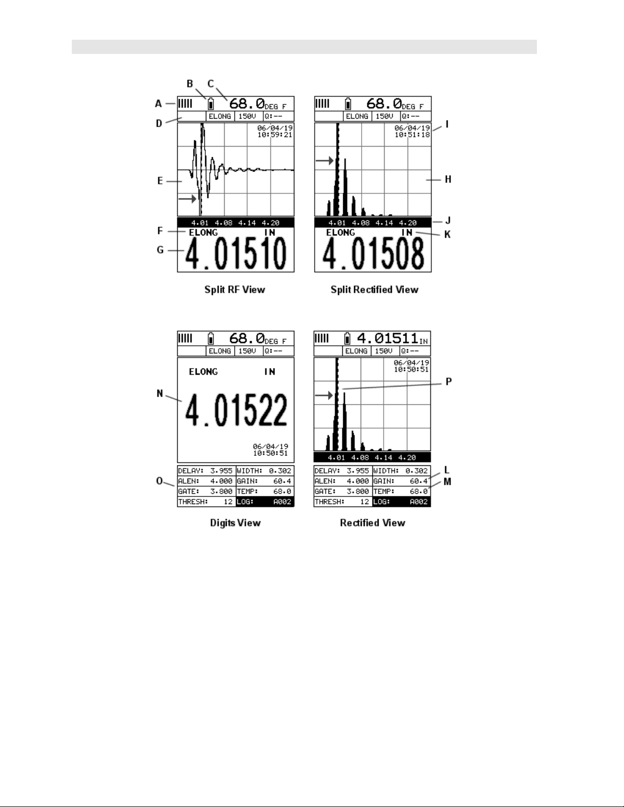
have a brief look at the screens you’ll be looking at most often:
A. Repeatability/Stability Indicator – Indicates the reliability of the measured
bolt length. When all the vertical bars are fully illuminated and the last digit on
the digital thickness value is stable, the MiniMax is reliably measuring the
same value on a consistent basis.
B. Battery Icon – Indicates the amount of battery life the MiniMax has
remaining.
4
Page 11

MiniMax Bolt Tension Monitor
C. Temperature – Indicates the current temperature of either the temperature
sensor, or manual value entered.
D. Feature Status Bar – Indicates the features currently enabled and in use:
Alarm
Quantity
Pulser Voltage
Q-Factor (wave correlation)
E. RF A-Scan Display (split screen) – Displays the radio frequency sound wave
reflection returned the opposite end of the bolt being measured. The RF view
displays both the positive and negative cycles.
F. Quantity – Displays the current quantity setting used (elongation, load, stress,
strain or time).
G. Digital Measurement – Display in inches, millimeters, KSI, KIPS, %strain,
time (nanoseconds).
H. Rectified A-Scan Display – Displays either the positive or negative half cycle
wave reflection returned from the opposite end of the bolt being measured,
depending on the polarity selected.
I. Time & Date – Feature to display either the time, date, or both time and date
on the main measurement screen.
J. Length Division Markers – Measurement scale of length.
K. Units – Displays the current measurement units being used (English, Metric).
L. Gain – The current gain setting can be adjusted at any time while in
measurement mode.
M. Temperature – Refer to (C) above. The location of the temperature is
displayed in this location when the hot menus are shown. Notice in (C) the
view is split screen and temperature is displayed in the top right corner of the
display. When the temperature mode is set ‘manual’, the value can be
changed at any time.
N. Digital Measurement – Display in inches, millimeters, KSI, KIPS, %strain,
time (nanoseconds).
O. Hot Menu items – We call this menu section our “hot menu”, as these items
are the most commonly adjusted features, requiring quick access from the
user. They can be displayed and scrolled by pressing the key at any
time. The key advances forward and the key backwards to the next
hot menu item.
P. Detect/Gate/Threshold
MiniMax is currently detecting on the waveform. Notice the horizontal line
with an arrow pointing at the detection point. This is the ‘gate’, and the height
of the line from the baseline is the ‘threshold’ level.
– The broken dotted line demonstrates where the
5
Page 12
Dakota Ultrasonics
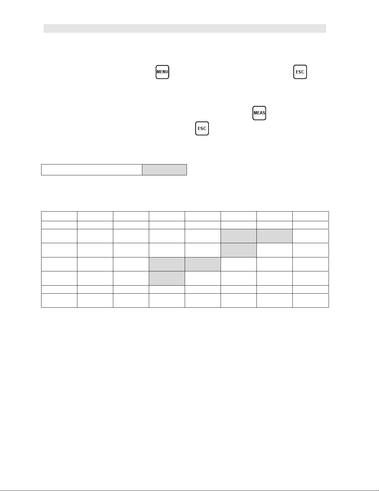
2.4 Tabbed & Hot Menu Reference
The following table is a quick menu reference guide of the tabbed menu items, which
can be accessed by pressing the key multiple times to tab right, or the key
multiple times to tab left through the tabbed menus. The MiniMax has 11 tabbed
menu titles and multiple submenu items as illustrated below. The MiniMax also has
1 ‘hot menu’ subset of commonly adjusted menu items. They can be quickly
accessed from the main measurement screen by pressing the key multiple
times to access and tab right, or pressing the key multiple times to tab left
through the hot menu cells. Refer to Chapter Four for additional definitions and
information on the keypad and menu items.
Hot Menu Items
Note: “Log” and “Temp” are also listed in the Hot Menu, and are used to access data storage if no log
file is currently open, or display log or grid file if open, as well as display the temperature.
Start >>
CAL MATL GEOM DISP TUNE GATES AUTO SETUP
ZERO MODE UNITS QUANTITY VIEW PULSE POLARITY AUTO SET OPEN
ZERO TYPE LOAD
MEASURE
ZERO
LOAD CAL
MODE
LOAD CAL
CALC
RECT WAVE DIGITIZER LANGUAGE
DETECT
VELOCITY LOAD
STRESS
FACTOR
TEMP COEF EFFECTIVE
FACTOR
OFFSET
AREA DELAY GAIN DEFAULT
LEN
CONTRAST PULSER
VOLTAGE
BACKLIGHT DAMPING THRESHOLD
WIDTH GAIN STEP
MARK
GATE APPROX LEN
(ALEN)
DELETE
1
SAVE
SETUP
6
Page 13

>> End
DATA UTILS XFER
NEW TEMP MODE UPGRADE
EDIT ALARM CAPTURE TO
OPEN ALARM LOW ABOUT
CLOSE ALARM HIGH
DELETE ONE
FILE
DELETE ALL
DATA
SHOW DATE
SUMMARY
KEY CLICK
SET DATE
GAUGE
FILE
MiniMax Bolt Tension Monitor
7
Page 14

CHAPTER THREE
QUICK START GUIDE
3.1 Overview
This section demonstrates the basic procedures for setting up and measuring bolts
using the MiniMax. More in depth explanations pertaining to the individual functions
and features can be found in the chapters that follow.
Here we go!
3.2 Getting the MiniMax ready
Making all the connections
In order to get the MiniMax ready for operation; the following connections must
be made:
1) Remove the MiniMax from the carrying case.
2) Connect the transducer cable to the transducer and plug it into the MiniMax.
3) If a temperature sensor is being used, connect the sensor to the MiniMax.
3.3 Setting up the MiniMax
Please Read: In this section the MiniMax will be setup in its simplest form.
Remember this is only a quick start guide to get the user up and measuring bolts.
Before we setup the gauge to measure basic elongation, the following assumptions
must be made: A preset material type will be used. The user will not be re-measuring
the fasteners at a later date to monitor relaxation of the joint over time. This
eliminates the need for an instrument zero/calibration. All these assumptions will be
answered and explained in detail in the chapters that follow.
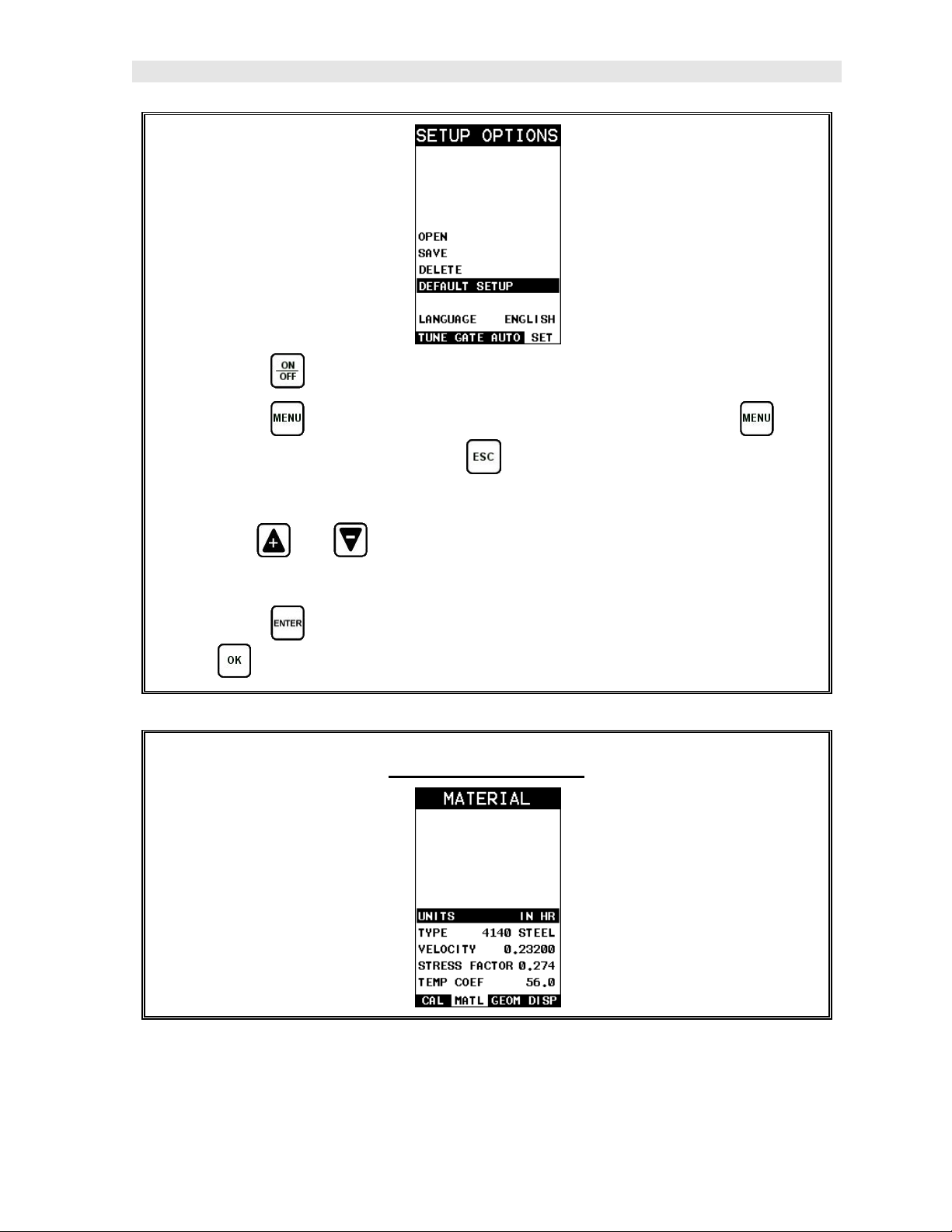
Selecting Default Setup
8
Page 15
MiniMax Bolt Tension Monitor
1) Press the key to power up the MiniMax.
2) Press the key once to activate the menu items tab. Press the key
multiple times to tab right and the key multiple times to tab left until the
SETUP menu is highlighted and displaying the submenu items.
3) Use the and arrow keys multiple times to scroll through the sub
menu items until DEFAULT SETUP is highlighted.
4) Press the key to display the confirmation screen, followed by pressing
the key to load the default setup.
Selecting the Units
9
Page 16
Dakota Ultrasonics
Note: The default setup, selected in the previous section, automatically
defaults to English units – inches. Follow the procedure below to change the
units to Metric, if needed.
1) Press the key multiple times to tab right and the key multiple times
to tab left until the MATL menu is highlighted and displaying the submenu
items.
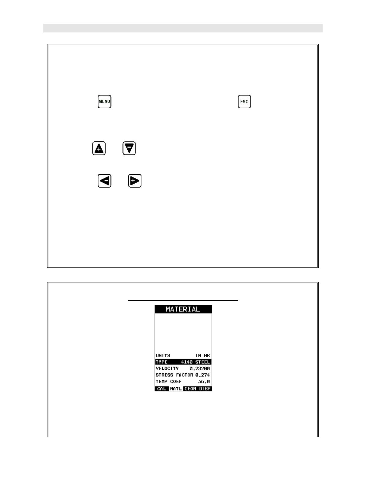
2) Use the and arrow keys to scroll through the sub menu items until
UNITS is highlighted.
3) Press the and arrow keys to scroll through the unit options IN
(inches), IN HR (inches hi resolution), MM (millimeters), and MM HR
(millimeters hi resolution).
Note: The high-resolution options display an additional digit of resolution to the
measurement. This mode is typically used when measuring very short bolts
with very little elongation.
Selecting the Material Type
This section allows the user the ability to select a material from a list of preset
material types. Keep in mind that we are measuring elongation only. If your
material is not in the list, select a similar material type. When measuring in
10
Page 17
MiniMax Bolt Tension Monitor
elongation mode, the measurement consists of a difference equation only
(Loaded Length – Unloaded Length = Length). Therefore, it doesn’t matter if
the ultrasonic length is different from the actual physical length, because the
Length will be the same. Example: 2.0080” physical loaded length – 2.0000”
physical unloaded length = 0.0080” Length which is equivalent to 2.1080”
ultrasonic loaded length – 2.1000” ultrasonic unloaded length = 0.0080”
Length.
1) Press the and arrow keys multiple times to scroll through the sub
menu items until TYPE is highlighted.
2) Press the key to display the list material types.
3) Press the and arrow keys multiple times to scroll through the
material list until the appropriate type is highlighted.
4) Press the key to display the confirmation screen.
5) Press the key to select the type and return to the menu screen, or
to cancel selecting the material type.
3.4 Creating a New Group to Store Measurements
Now that the MiniMax is all setup, this section will explain how to get started
measuring unloaded initial lengths. In order to do this, we need to create a group
that contains bolts. A group can have up to 250 bolts, each bolt containing 1
reference length (L-REF), and up to 51 elongations. Keep in mind that the MiniMax
uses a group to store measurements and all gauge settings at the time of
measurement.
Creating a Group Name
11
Page 18
Dakota Ultrasonics
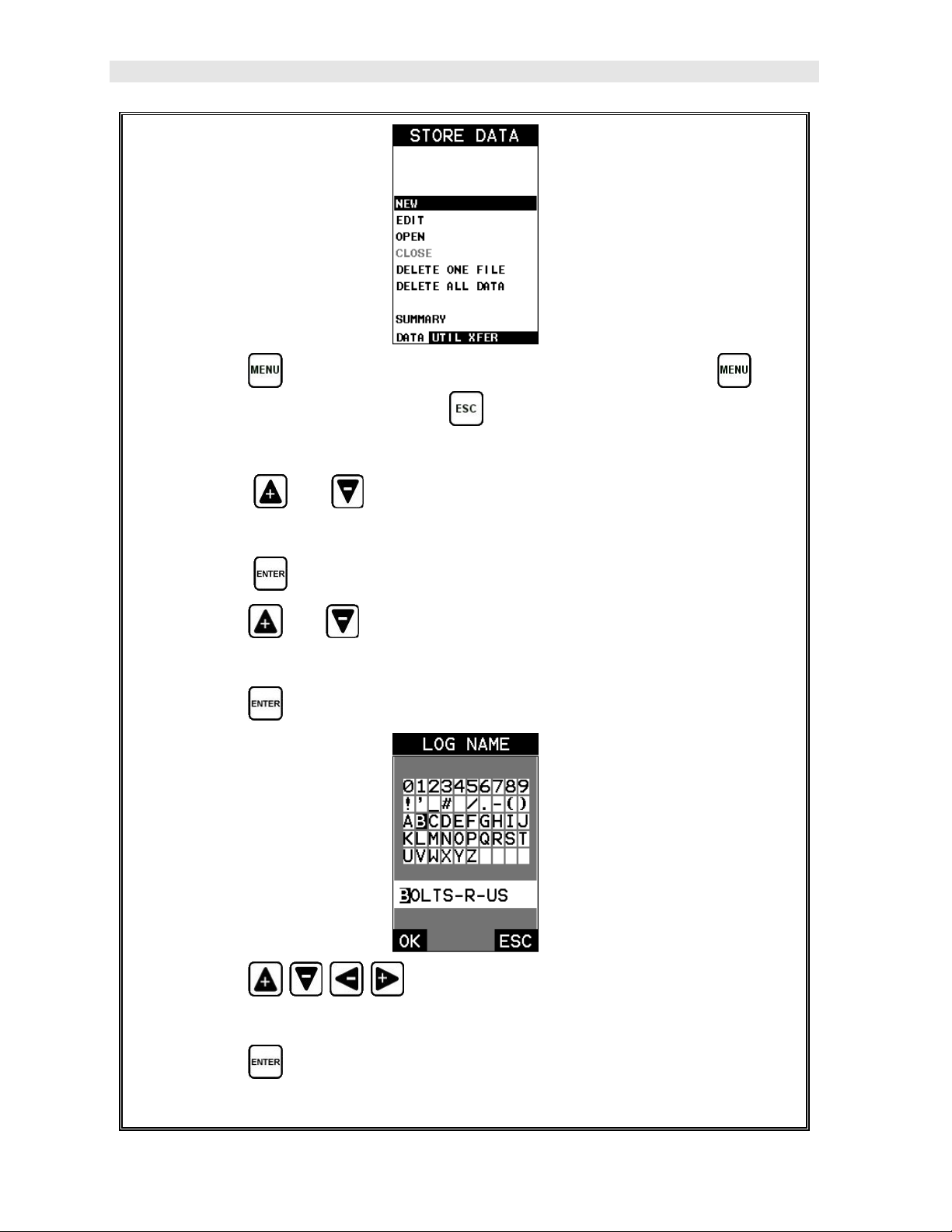
1) Press the key once to activate the menu items tab. Press the key
multiple times to tab right, and the key multiple times to tab left, until the
DATA menu is highlighted and displaying the submenu items.
2) Press the and arrow keys multiple times to scroll through the sub
menu items until NEW is highlighted.
3) Press the key to display the New Group Edit Box.
4) Press the and arrow keys multiple times to scroll through the new
Group List Items until NAME is highlighted.
5) Press the key to activate the Alpha Edit Box.
6) Press the arrow keys to highlight the appropriate alpha
characters.
7) Press the key to select a character and advance to the next field of the
Group Name.
12
Page 19
MiniMax Bolt Tension Monitor
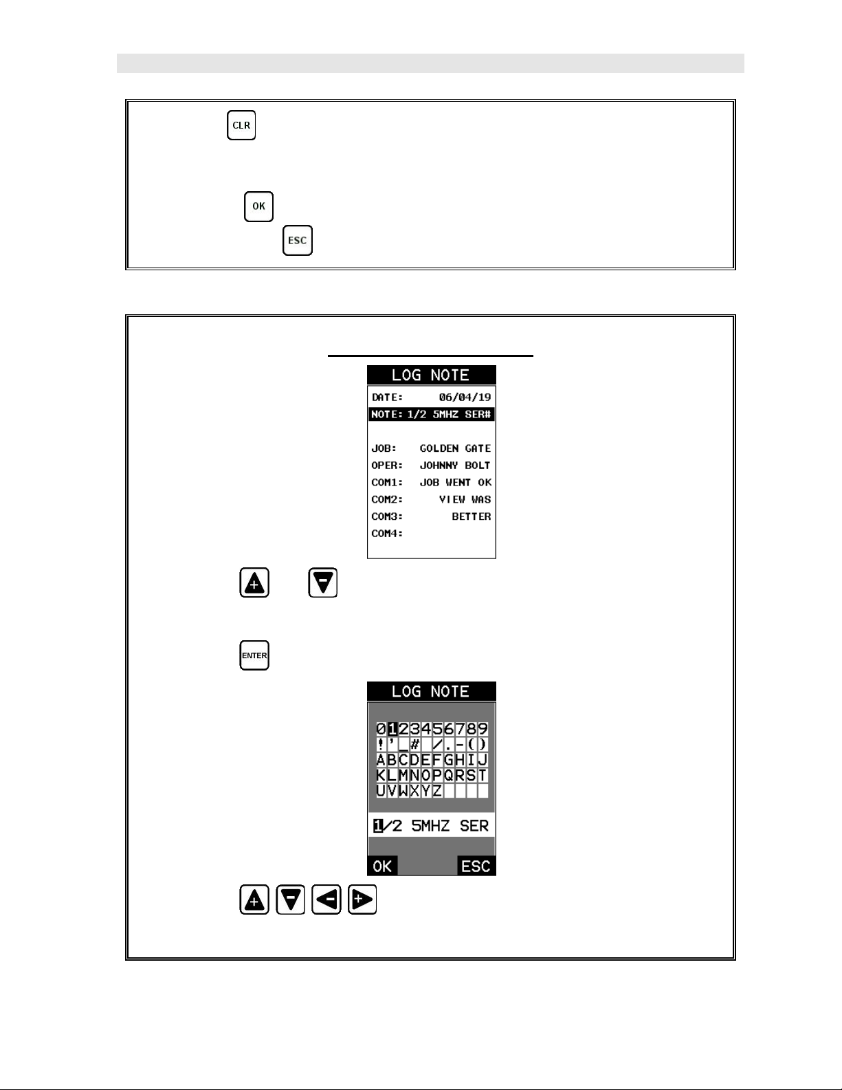
8) Use the key to backspace if necessary.
9) Repeat steps 6 - 8 until the Group Name is completed.
10) Press the key to save the Group Name and return to the Group List
Items menu, or to cancel entering the Group Name.
Creating a Group Note
1) Press the and arrow keys multiple times to scroll through the new
Group List Items until NOTE is highlighted.
2) Press the key to activate the Alpha Edit Box.
3) Press the arrow keys to highlight the appropriate alpha
characters.
13
Page 20
Dakota Ultrasonics
4) Press the key to select a character and advance to the next field of the
Group Note.
5) Use the key to backspace if necessary.
6) Repeat steps 3 - 5 until the Group Note is completed.
7) Press the key to save the Group Note and return to the Group List
Items menu, or to cancel entering the Group Note.
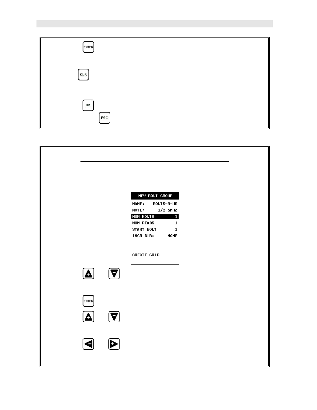
Selecting the Number of Bolts in the Group
Note: A group can contain up to 250 bolts. There must be at least 1 bolt in a
group.
1) Press the and arrow keys multiple times to scroll through the new
Group List Items until NUM BOLTS is highlighted.
2) Press the key to display the Digits Edit Box.
3) Press the and arrow keys multiple times to scroll the highlighted
value.
4) Press the and arrow keys multiple times to scroll the digit
locations.
14
Page 21
MiniMax Bolt Tension Monitor
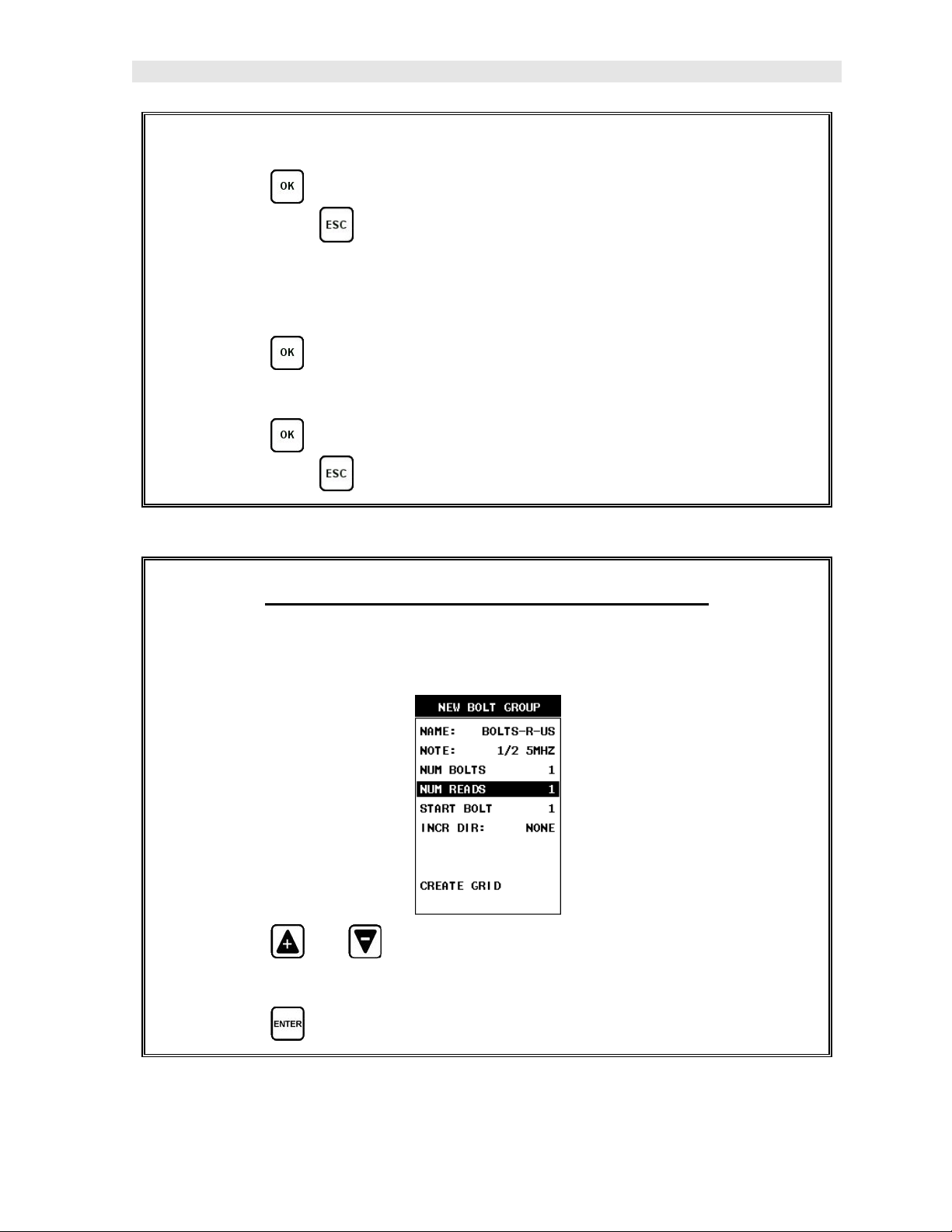
5) Repeat steps 3 & 4 until the NUM BOLTS value is correctly displayed.
6) Press the key to save the NUM BOLTS and return to the Group List
Items menu, or to cancel entering the NUM BOLTS.
Note: If a number greater than 250 is entered, an error message box “VALUE
IS OUT OF RANGE” will be displayed.
7) Press the key to display the Digits Edit Box and re-enter the NUM
BOLTS.
8) Press the key to save the NUM BOLTS and return to the Group List
Items menu, or to cancel entering the NUM BOLTS.
Selecting the Number of Readings Per Bolt
Note: A bolt can have up to 51 possible measurements and 1 initial length (L-
REF). There must be at least one reading per bolt.
1) Press the and arrow keys multiple times to scroll through the new
Group List Items until NUM READS is highlighted.
2) Press the key to display the Digits Edit Box.
15
Page 22
Dakota Ultrasonics
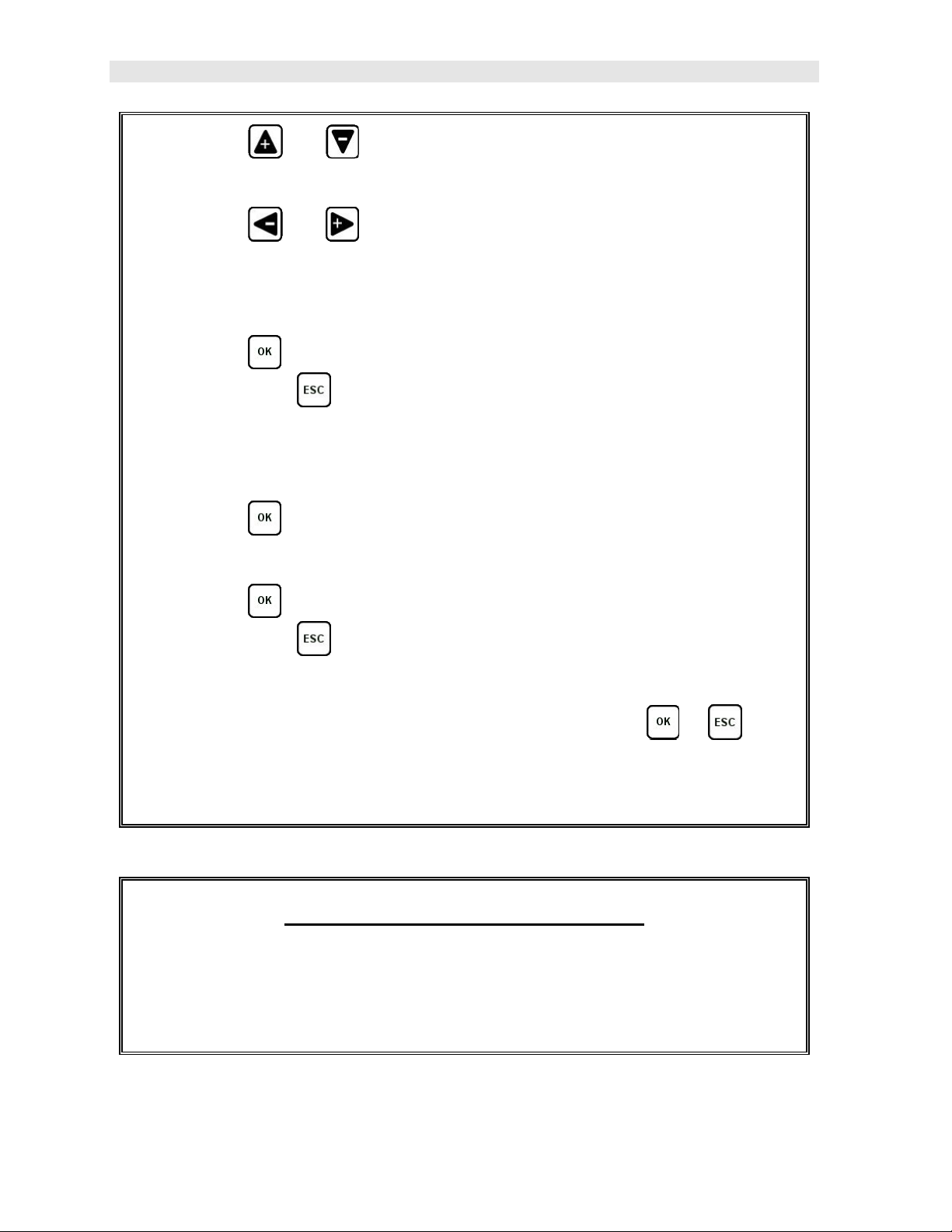
3) Press the and arrow keys multiple times to scroll the highlighted
value.
4) Press the and arrow keys multiple times to scroll the digit
locations.
5) Repeat steps 3 & 4 until the NUM READS value is correctly displayed.
6) Press the key to save the NUM READS and return to the Group List
Items menu, or to cancel entering the NUM READS.
Note: If a number less than 1 or greater than 51 is entered, an error message
box “VALUE IS OUT OF RANGE” will be displayed.
7) Press the key to display the Digits Edit Box and re-enter the NUM
READS.
8) Press the key to save the NUM READS and return to the Group List
Items menu, or to cancel entering the NUM READS.
If there’s not enough memory available to create the group, an error message
box “NOT ENOUGH MEMORY” will be displayed. Press the or key
to return to the Group List Items menu. It may be necessary to free some
memory in the MiniMax at this time.
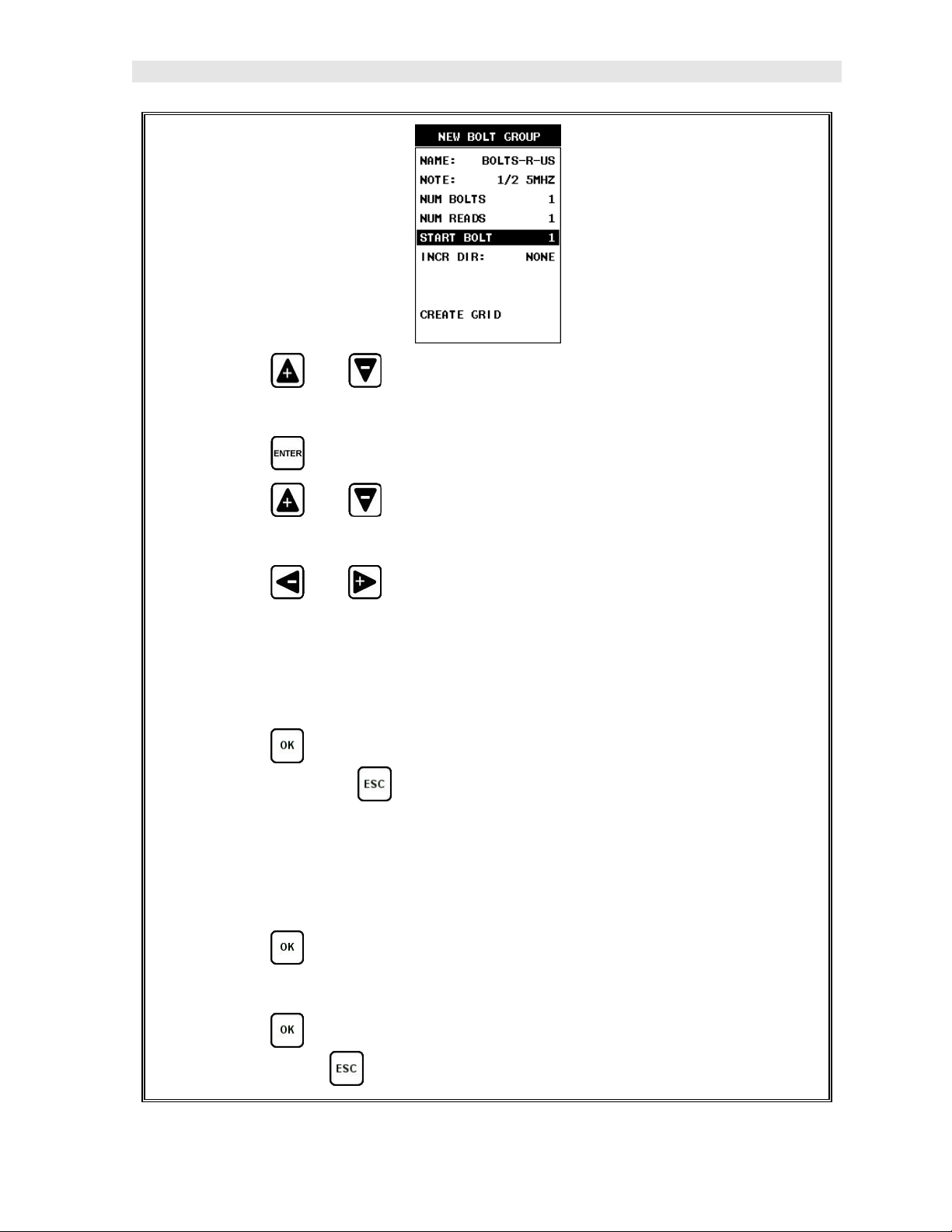
Selecting the Starting Bolt Number
Note: Depending on the application and layout of the project, the user won’t
always want the starting bolt to be 1. This feature allows the user to define
what the starting number will be.
16
Page 23
MiniMax Bolt Tension Monitor
1) Press the and arrow keys multiple times to scroll through the new
Group List Items until START BOLT NUM is highlighted.
2) Press the key to display the Digits Edit Box.
3) Press the and arrow keys multiple times to scroll the highlighted
value.
4) Press the and arrow keys multiple times to scroll the digit
locations.
5) Repeat steps 3 & 4 until the START BOLT NUM value is correctly
displayed.
6) Press the key to save the START BOLT NUM and return to the Group
List Items menu, or to cancel entering the START BOLT NUM.
Note: If a value is enter that is greater than the maximum number of bolts
allowed per group (250), an error message box “VALUE IS OUT OF RANGE”
will be displayed.
7) Press the key to display the Digits Edit Box and re-enter the START
BOLT NUM.
8) Press the key to save the START BOLT NUM and return to the Group
List Items menu, or to cancel entering the START BOLT NUM.
17
Page 24
Dakota Ultrasonics
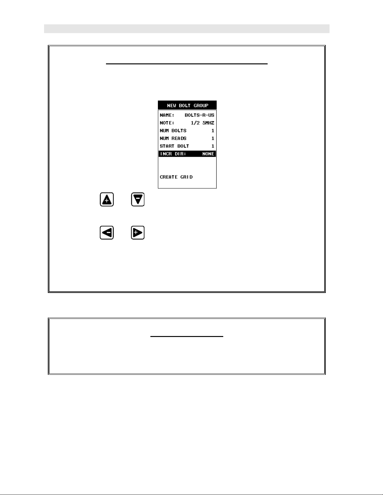
Selecting the Auto Increment Direction
The Auto Increment feature gives the user the ability to specify which direction
to advance the cursor after storing a reading.
1) Press the and arrow keys multiple times to scroll through the new
Group List Items until INCR. DIR is highlighted.
2) Press the and arrow keys multiple times to toggle the Increment
direction NONE, NORTH, EAST, SOUTH, or WEST.
3) When the correct Increment direction is displayed, continue on to the next
section “Saving the Group”.
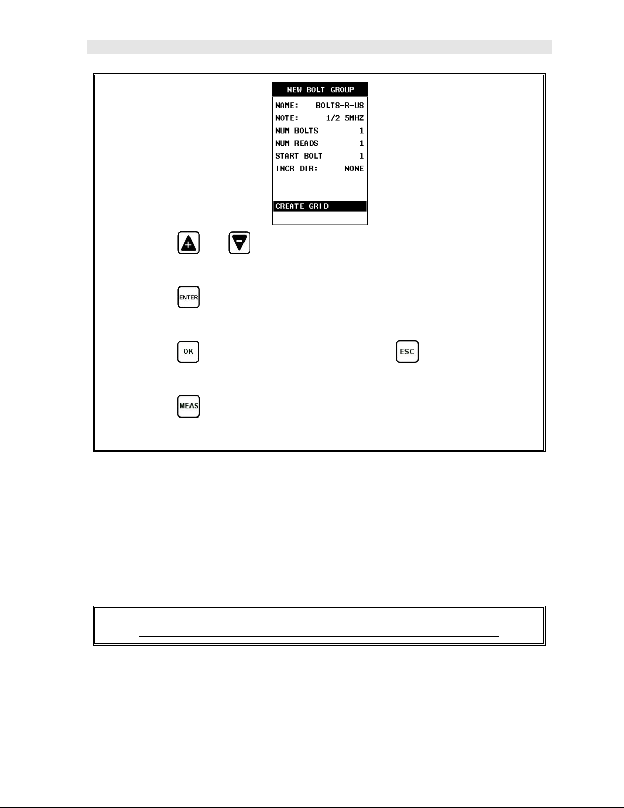
Saving the Group
Once all the parameters are set, the user has the option of saving or canceling
the new group.
18
Page 25
MiniMax Bolt Tension Monitor
1) Press the and arrow keys multiple times to scroll through the new
Group List Items until CREATE GROUP? is highlighted.
2) Press the key to accept the group parameters, and activate the
confirmation screen.
3) Press the key to save the New Group, or the key to cancel the
New Group setup and return to the DATA menu.
4) Press the key to return to the measurement screen to begin measuring
reference lengths.
3.5 Setting the Approximate Length
In order to utilize the AUTO SET feature of the MiniMax, when measuring reference
lengths, the MiniMax has to know where to start looking for the detection. We can
accomplish this by entering an approximate length into the gauge. The MiniMax will
automatically take the value entered and scan +/- 5% in both directions of the
approximate length for the detection signal. The approximate length is a very
valuable feature that can be used to pin point a specific detection area. This feature
will be further discussed later in the manual.
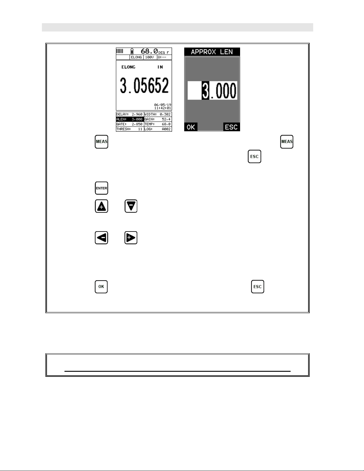
Setting the Approximate Length using the Hot Menus
19
Page 26
Dakota Ultrasonics
1) Press the key once to activate measure menu items. Press the
key multiple times to advance to the next cell right and the key multiple
times to advance to the next cell left, until the ALEN cell is highlighted.
2) Press the key to display the Digits Edit Box.
3) Press the and arrow keys multiple times to scroll the highlighted
value.
4) Press the and arrow keys multiple times to scroll the digit
locations.
5) Repeat steps 3 & 4 until the ALEN value is correctly displayed.
6) Press the key to return to the measurement screen, or to cancel
entering the ALEN.
The user can also access and set the approximate length from the tabbed menus.
However, this method is more tedious than making the adjustments using the Hot
Menus. The procedure using the tabbed menus is outlined below:
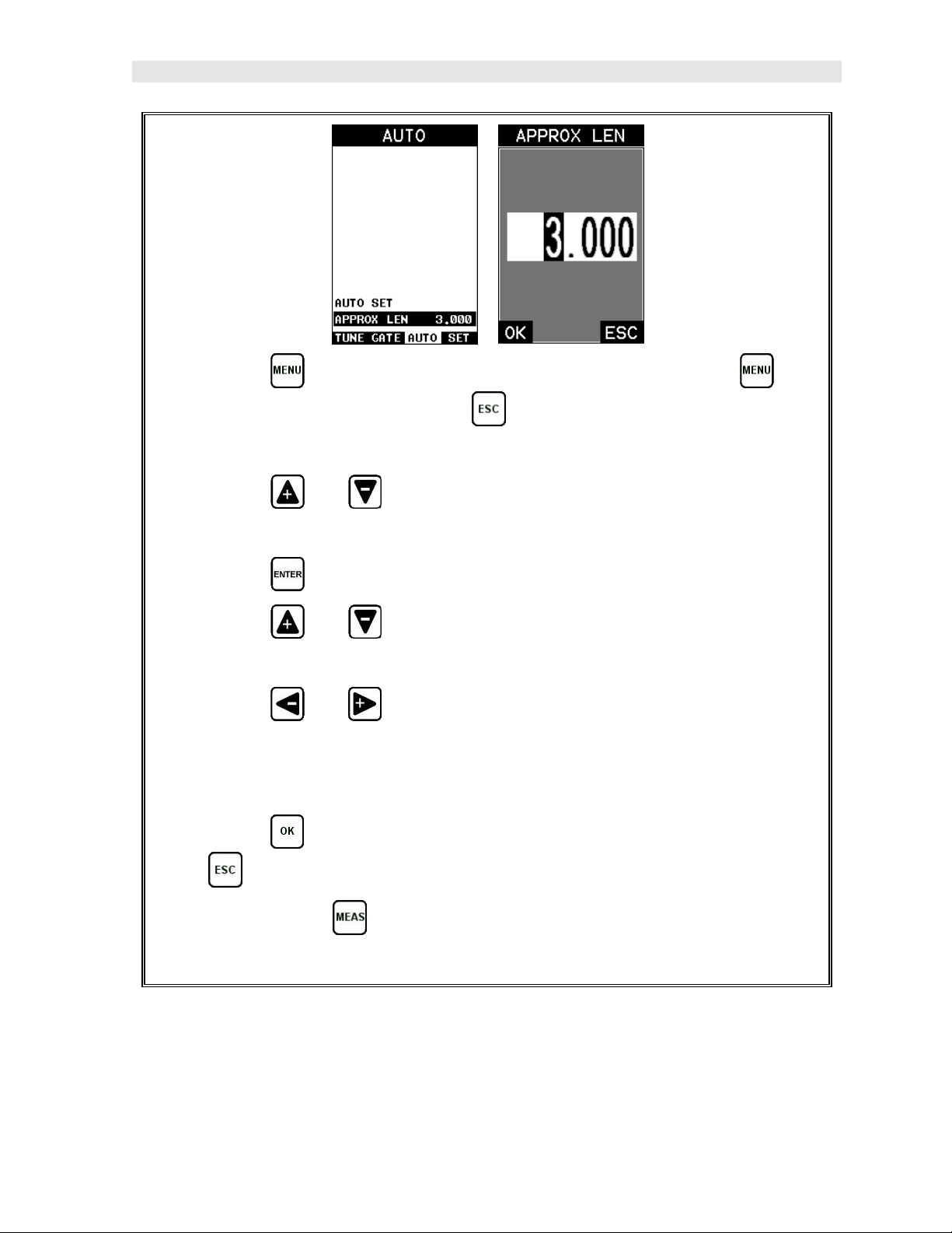
Setting the Approximate Length using the Tabbed Menus
20
Page 27
MiniMax Bolt Tension Monitor
1) Press the key once to activate the menu items tab. Press the key
multiple times to tab right, and the key multiple times to tab left, until the
AUTO menu is highlighted and displaying the submenu items.
2) Press the and arrow keys multiple times to scroll through the sub
menu items until APPROX. LEN. is highlighted.
3) Press the key to display the Digits Edit Box.
4) Press the and arrow keys multiple times to scroll the highlighted
value.
5) Press the and arrow keys multiple times to scroll the digit
locations.
6) Repeat steps 4 & 5 until the Approx. Len. value is correctly displayed.
7) Press the key to set the Approx. Len. and return to the menu screen,
or to cancel entering the Approx. Len..
8) Finally, press the key to return to the measurement screen and begin
measuring reference lengths.
21
Page 28
Dakota Ultrasonics
3.6 Measuring Reference Lengths
At this point, the MiniMax is setup and ready to start measuring reference lengths.
We’ve already setup a bolt group to store the reference length data, and now need to
display the group storage locations prior to making measurements.
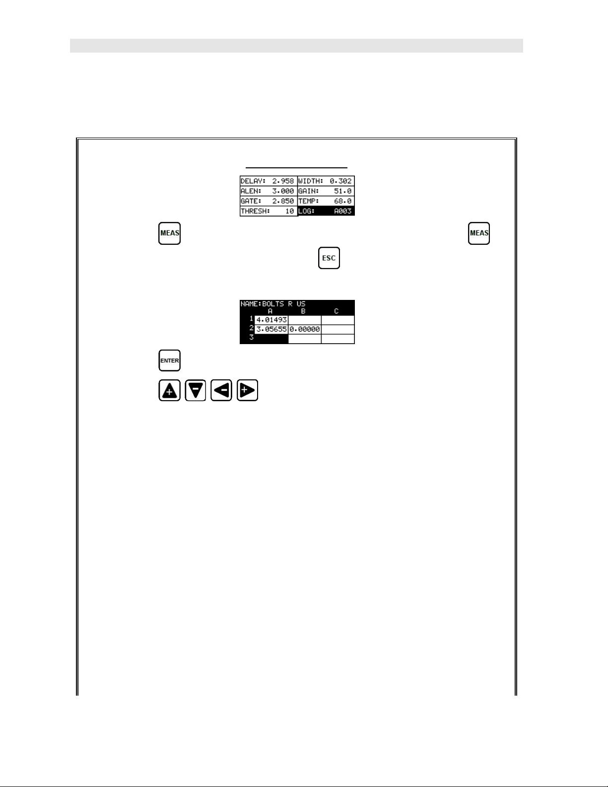
Storing a Reading
1) Press the key once to activate measure menu items. Press the
key multiple times to move right and the key multiple times to move left
until the LOG cell is highlighted.
2) Press the key to display the Group View Box.
3) Press the arrow keys to scroll the target cell cursor to the
desired storage location.
Note: The approximate lengths must always be located in the first column A for
all bolts in the group.
4) Place a small amount of couplant on the transducer and attached it to the
bolt. Make sure that the transducer is seated so that there is no couplant
layer creating a gap between the transducer and bolt. This can be
accomplished by rotating the transducer clockwise and counter clockwise
while applying a very small amount of pressure to seat the transducer firmly
against the bolt.
Important Note: Always be sure to place the transducer in the same exact
location if it will be removed in between reference lengths and elongation
measurements. This will eliminate any potential sound path error caused by
22
Page 29
MiniMax Bolt Tension Monitor
moving the transducer to a completely different location on the bolt, thus
causing potentially erroneous measurements. Be consistent and as methodical
in your methods as possible. This will help to avoid transducer placement
errors.
5) Press the key, located in the bottom left corner of the keypad, to locate
the detection point, or end of the bolt.
6) Press the key to save the current approximate length in the highlighted
cell location.
Note: If the measurement was saved in error, press the key at anytime to
clear the stored reading and re-measure using the steps 4 – 6 above.
Note: The Group View Box can be aborted at any time by pressing the
key.
3.7 Measuring Elongations
Now that the reference lengths have been measured and saved, we’re ready to start
measuring elongation values. We’ll start off by assuming the bolt has been stretched
or tightened, the transducer has been once again coupled to the bolt in the same
location as before, and we’re ready to measure the elongation as follows:
Measuring an Elongation
Important Note (recap): Always be sure to place the transducer in the same
exact location if it will be removed in between reference lengths and elongation
measurements. This will eliminate any potential sound path error caused by
moving the transducer to a completely different location on the bolt, thus
causing potentially erroneous measurements. Be consistent and as methodical
in your methods as possible. This will help to avoid transducer placement
errors.
23
Page 30
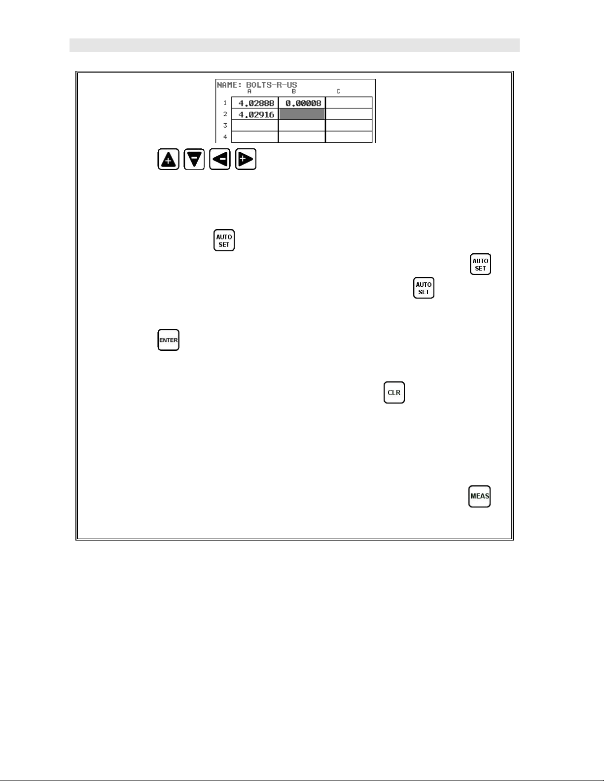
Dakota Ultrasonics
1) Press the arrow keys to scroll the target cell cursor to the
desired storage location.
Note: Elongation values must be stored in column B - ZZ.
Note: Do not press the key, while measuring elongation’s, as this
activates a high speed mode used specifically with our shut-off box. The
feature is only used when measuring reference lengths. If the key is
accidentally pressed, press it again to turn the high speed mode off.
2) Press the key to save the current elongation in the highlighted cell
location.
Note: If the measurement was saved in error, press the key at anytime to
clear the stored reading and re-measure using steps 1 & 2 above.
3) Continue to repeat this process until all the elongation measurements have
been completed.
Note: The Group View Box can be aborted at any time by pressing the
key.
24
Page 31

CHAPTER FOUR
KEYBOARD, MENU, & CONNECTOR REFERENCE
4.1 Menu Key (Operation & Sub Menus)
The Menu key activates the primary menu structure containing 11 menu tab groups.
These tab groups then contain sub menu items, or functions. The sub menu items
have been organized in tab groups according to how closely they are related to the
individual tab group names. Let’s first get familiar with how to move around in these
tabs before continuing on to the sub menu functions. This procedure is outlined
below:
25
Page 32

Dakota Ultrasonics
Activating and Getting Around in the Menu Items
1) Press the key once to activate the menu items tab. Press the key
multiple times to tab right, and the key multiple times to tab left until the
desired tab group is highlighted and displaying the submenu items (A).
Now that you’re familiar with activating and moving amongst the tab groups, let’s
have a look at how to move around in the sub menu items as follows:
Getting Around in the Sub Menu Items
1) Use the and arrow keys to scroll through the sub menu items until
the desired function is highlighted. The sub menu items are illustrated in the
diagram above (B).
2) Depending on which function is highlighted, use the and arrow
keys to scroll the options/values, or the key to activate the Digit Edit
and List Box options.
The sections to follow will provide the user with an explanation of the sub menu
functions:
26
Page 33

MiniMax Bolt Tension Monitor
4.2 CAL – Menu
ZERO MODE: The MiniMax is zeroed in much the same way that a mechanical
micrometer is zeroed. There are three zero mode options available in the MiniMax –
FIXED, ONE POINT, TWO POINT and AUTO. Selecting the proper mode is
dependent on the application requirements, but the most convenient mode of
preference is - AUTO. Refer to page 45, for an explanation of this important
procedure.
ZERO VALUE: Depending on the Zero Mode selected above, the actual zero value
will be calculated and displayed in this sub menu item. The user can edit this value
at anytime from this sub menu item. Refer to page 45 for a further explanation.
MEASURE ZERO: Once the Zero Mode has been selected above, this function
displays and calculates the actual measurement screen containing the known
physical length, velocity, and temperature coefficient of the calibration standard
versus the ultrasonic length. . Refer to page 45 for a further explanation.
LOAD CAL MODE: Enables and disables the field calibration feature of the
MiniMax. This is used to compare known and ultrasonic loads. Refer to page 108
for a further explanation.
LOAD CAL CALC: This feature is used to calculate a linear regression or vector
curve, once the Load Cal Mode is enabled and known and ultrasonic loads have
been entered and ultrasonically measured. If the regression option was selected in
Load Cal Mode, a correction load offset and load factor will be calculated. If the
vector option was selected, a load factor will be calculated and the offset will be set to
zero. Refer to page 108 for a further explanation.
27
Page 34

Dakota Ultrasonics
4.3 MATL (material) – Menu
UNITS:
unit ( IN - .0001, INHR - .00001, or MM - .001, MMHR - .0001 ), Using the
abbreviation HR to represent High Resolution.
TYPE:
contains a velocity, stress factor, and temperature factor. When a type is selected,
these values are displayed in the sub menu items below and can be edited by the
user at anytime.
VELOCITY: This feature allows the user to edit the material velocity at anytime.
Once a material type is selected, the velocity of the selected material type is stored in
this sub menu item and can be edited a by the user if necessary.
STRESS FACTOR: This feature allows the user to edit the stress factor at anytime.
Once a material type is selected, the stress factor of the selected material type is
stored in this sub menu item and can be edited by the user if necessary. Refer to
page 99 for further info.
TEMP COEF: This feature allows the user to edit the material temperature coefficient
at anytime. Once a material type is selected, the temperature coefficient of the
selected material is stored in this sub menu item and can be edited by the user if
necessary. Refer to page 103 for further info.
Toggle between English and Metric units and multiple resolutions for each
Select the bolt material type from a preset list of material types. Each type
4.4 GEOM (geometry) – Menu
QUANTITY:
STRESS, and % STRAIN. Refer to page 123 for further info.
LOAD FACTOR:
typically determined by performing a field calibration and running a regression or
Selectable units of measure in terms of TIME, ELONGATION, LOAD,
The conversion factor from elongation to Load. This value is
28
Page 35

MiniMax Bolt Tension Monitor
vector using the MiniMax or utility software. Alternatively, the load factor can be
determined using the bolt calculator in the utility software. However, if extreme
accuracy is required, performing a field calibration is a must. This sub menu item
enables the user to edit the factor at anytime. Refer to page 106 for further info.
LOAD OFFSET:
calibration is performed and regression calculated a small offset (y intercept) will
result. This value is a constant added or subtracted from the measurement, and will
result in correction to the load quantity. This sub menu item enables the user to edit
the offset value at anytime. Refer to page 106 for further info.
AREA:
stress. Set to zero if the user is not measuring the quantity in terms of stress. This
sub menu item enables the user to edit the area at anytime. Refer to page 106 for
further info.
EFFECTIVE LENGTH: The length of the region of the fastener under stress (the
distance between the nut plus some amount of additional stress that occurs in the
head and nut(s) of the fastener). This sub menu item enables the user to edit the
effective length at anytime. Refer to page 106 for further info.
The cross sectional area of the fastener being measured. Used to calculate
Normally the Load Offset is set to zero. However, when a field
4.5 DISP (display) – Menu
VIEW:
to page 124 for further info.
CONTRAST: Adjustable display contrast for variable light conditions. An arbitrary
scale of 1-20 has been implemented, with the darkest setting at 20. Refer to page
148 for further info.
BACKLIGHT: Selectable OFF, ON, AUTO, or INVERT back light option. Refer to
page 149 for further info.
DELAY: Provides the user the ability to change where the left side of the display
window starts according to time which is converted to a length, in English or Metric
units. Refer to section 12.3 for further info.
WIDTH:
measurement area. It functions a lot like a zoom on a camera. Refer to section 12.3
for further info.
Selectable RF wave, RECT (rectified), and DIGITS (large digits) views. Refer
Provides the user the ability to change the overall size of the viewable
29
Page 36

Dakota Ultrasonics
RECT WAVE: This option provides the user an outlined or filled view option when
the display setting is in RECT (rectified) wave mode only. Refer to page 124 for
further info.
DETECT MARK: Selectable graphics option for the point of detection on the
waveform: Line, Box, Dots, None. Offers the user a graphics preference on how
they prefer to view the detection on the waveform. Refer to page 150 for further info.
4.6 TUNE – Menu
PULSE: The DFX-8 has an adjustable pulse width for both high penetration and
resolution applications. The pulse width refers to the duration of time the pulser is
on. There are three different types of pulsers built into the MiniMax – Spike, Square
Wave, and Tone Burst with adjustable voltage options of 100-400 volts and select
settings of Spike, Thin, Wide, HV Spike, HV Thin, HV Wide, TB 10MHz, TB 5MHz,
TB 2MHz, and TB 1MHz. Refer to page 160 for a further explanation.
PULSER VOLTAGE: Adjustable voltage of 100-400 volts, depending on the pulser
option selected. The standard setting is 150 volts. This enables the MiniMax to offer
greater penetration for difficult material types, or increased resolution on noisy
materials. Refer to page 153 for a further explanation.
DAMPING: Provides the user with multiple input impedances to match the
impedance of the transducer, and optimized overall transducer performance. Refer
to page 154 for further info.
GAIN:
with the attenuator feature above. This feature is used to increase/decrease the
power or amplitude of the signal. This might easily be considered as similar to
turning the volume up or down on a stereo receiver. Refer to page 131 for further
info.
GAIN STEP: The gain increment step size for each key press. If the step size is set
to 3, then each key press will increase/decrease the gain +/-3dB. Refer to page 131
for further info.
DIGITIZER:
number of shots/samples. The higher the sample digitizer rate, the better the
resolution, but the slower the update rate/speed and vise versa. Refer to page 153
for a further explanation.
The MiniMax has 100dB gain range from (-30 to 70 dB), used in conjunction
Increases the measurement resolution by 2x or 4x by increasing the
30
Page 37

MiniMax Bolt Tension Monitor
4.7 GATES – Menu
POLARITY:
feature toggles which stroke of the cycle the crossing detection uses, either positive
or negative. Refer to page 156 for further info.
GATE:
the waveform, and ignore others. The Gate1 feature adjusts the start of the gate,
according to time/distance. Gate 1 can be used in all pulse-echo and echo-echo
measurement modes. Refer to page 135 for further info.
THRESHOLD1: Enables the user to set the sensitivity level of Gate1. The amplitude
of the signal must reach or exceed the threshold level before a measurement is
detected. Refer to page 135 for further info.
The MiniMax operates on a zero crossing detection principal. This
Gates allow the user to view a specific measurement range, or sections of
4.8 AUTO – Menu
AUTO SET:
viewable display area. Used when measuring reference lengths only. Refer to
section 12.9 for further info.
APPROX LEN:
length of the fastener must be entered. The approximate length gives the MiniMax
some idea of where to turn on the receiver and look for the detection, or end of the
bolt. This sub menu item enables the user to edit the length at anytime. Refer to
section 12.9 for further info.
Automatically locates the detection point if the measurement is out of the
In order for the user to use the Auto Set feature, an approximate
31
Page 38

Dakota Ultrasonics
4.9 SETUP – Menu
OPEN:
These setups can be recalled and used at any time. Refer to page 178 for further
info.
SAVE:
modified or created by the user. Refer to page 179 for further info.
DELETE: Provides the user with the ability to delete specific setups previously save
in memory. Refer to page 182 for further info.
DEFAULT SETUP: Loads a basic default setup. Use only as a last resort when the
setups in the MiniMax have been corrupted and a computer is not accessible. Refer
to page 184 for further info.
LANGUAGE: Provides the user the ability to select different languages for the
MiniMax. Refer to page 185 for further info.
Displays a list of factory and user defined setups currently stored in memory.
Provides the user with the ability to save a custom setup that has been
4.10 DATA – Menu
NEW: Allows the user the ability to create a new alpha numeric grid, or sequential
log file with auto identifiers. It is equipped with custom parameters, rows, and
columns depending on the user’s application reporting requirements. Refer to page
165 for further info.
EDIT:
previously saved. Pre-defined coordinates cannot be changed once they have been
created. Refer to page 173 for further info.
OPEN:
files that currently exist in memory, from a list of grids. Refer to page 175 for further
info.
Gives the user the ability to change parameters of grid or sequential file
This function provides the user with the ability to recall grids or sequential log
32
Page 39

MiniMax Bolt Tension Monitor
CLOSE: Provides the user the ability to close a currently opened grid or sequential
log file. Refer to page 177 for further info.
DELETE ONE FILE: This function provides the user with the ability to delete one
individual grid or sequential log file from a list of multiple grids/files previously saved
in memory. Refer to page 170 for further info.
DELETE ALL DATA: This function provides the user with the ability to delete all files
currently stored in memory. Refer to page 172 for further info.
SUMMARY: Provides the user with an overall summary of the current data group
open/active. Refer to page 172 for further info.
4.11 UTIL (utilities) – Menu
TEMP MODE: This sub menu item enables the user to select the automatic
temperature compensation mode (manual, semi-auto, and auto). This feature is only
available to those units purchased with the automatic temperature compensation
option and probe. Note: Contact Dakota for information on upgrading the MiniMax.
Refer to page 91 for further info.
ALARM: Toggles alarm mode on, off, or audible. Refer to page 157 for further info.
ALARM LOW: Gives the user the ability to set the LO limit parameter. If the
measurement falls below this value, a red light will illuminate and sound the internal
beeper. Refer to page 157 for further info.
ALARM HIGH:
measurement exceeds this value, a red light will illuminate and sound the internal
beeper. Refer to page 157 for further info.
KEY CLICK: Gives the user the ability to set the level of the key press beeper OFF,
QUIET, or LOUD. Refer to page 160 for further info.
SET DATE: Gives the user the ability to set the internal date and time stamp in the
MiniMax. Refer to page 160 for further info.
SHOW DATE:
measurement screen. Refer to page 160 for further info.
Gives the user the ability to set the HI limit parameter. If the
Gives the user the ability display the time, date or both in the main
33
Page 40

Dakota Ultrasonics
4.12 XFER (transfer) – Menu
UPGRADE GAUGE:
most current firmware revision. Refer to page 162 for further info.
CAPTURE TO FILE:
files. Refer to page 163 for further info.
ABOUT: Provides the user with Dakota Ultrasonics contact information and the
MiniMax software version. Refer the Dakota Ultrasonics web site for information on
the latest firmware versions available for download.
Enables the user the ability to upgrade the MiniMax to the
Enables the user the ability to enable screen capture to .tiff
4.13 CLR (clear) Key
The primary functions of the CLR key, are to clear a measurement from a grid or
sequential log files cell location or set an obstruct, backspace in an Alpha Edit Box.
If a user has already saved a measurement and B-Scan to a cell location, use this
key to clear the measurement at any time.
4.14 MEAS (measurement mode) Key
The MEAS key puts the MiniMax into its primary mode of operation. In this mode,
the user has a complete view of the waveform, hot menu items, and measurement.
4.15 OK Key
The primary function of the OK key is confirmation of a change or selection. The OK
key also toggles between full or split screen view while in the main measurement
screen. If the MiniMax is displaying a data group, the OK key toggles an advance to
row number option.
34
Page 41

MiniMax Bolt Tension Monitor
4.16 ESC Key
The ESC key is used in the MENU, MEAS, and EDIT functions as a back or escape
key. If the MiniMax is displaying a group file, the OK key toggles the display view
options: Digits, RF, RECT views.
4.17 Arrow Keys
The Arrow Keys are used to navigate through the menus, increase/decrease values,
and toggle specific function keys.
4.18 ENTER key
The ENTER key is used in the overall menu selection process, to activate list and
edit boxes, display and save measurements to a group file location.
4.19 AUTO SET Key
The AUTO SET is an automatic measurement routine that attempts to locate the
detection and set all the scope parameters of the MiniMax.
4.20 ON/OFF Key
The ON/OFF key simply powers the unit either ON or OFF. Note: Unit will
automatically power off when idle for 5 minutes. All current settings are automatically
saved prior to powering off.
4.21 Navigating the Hot Menu
35
Page 42

Dakota Ultrasonics
The diagram above is a screenshot of the “Hot Menu” in the MiniMax. The Hot Menu
contain all the most regularly adjusted features. The primary purpose of the design
was to provide the user with an efficient way to make adjustments on the fly, while
continuing to have visibility of the A-Scan display. The following procedure outlines
the steps to navigate and make adjustments as follows:
Navigating Hot Menus
1) Press the key once to display the measure screen, and multiple times
to advance the cursor to the next cell right, or to advance to the next
cell left, until the desired function is highlighted.
2) Press the and arrow keys to scroll the options/values, or the
key to activate the Digit Edit and List Box options.
Note: This is a coarse adjustment. It’s the fastest and easiest way to
increment, decrement, or toggle the status however it does so in coarse steps.
Pressing the key will allo w the user to enter a specific target value.
This procedure above is universal for navigating through and selecting all
the features in the Hot Menus.
36
Page 43

4.22 Top & Bottom End Caps
The top & bottom end panels are where all connections are made to the MiniMax.
The diagram above shows the layout and description of the connectors:
Transducer Connector
Refer to Diagram: The transducer connector is a board mounted and shielded
LEMO “00”.
Temperature Sensor Connector
Refer to Diagram: The temperature sensor connector is a Shielded custom 5 pin
Lemo “1”.
Battery Cover (backup)
Refer to Diagram: The battery cover is the large round disk shown in the diagram.
Simply remove the cover when replacing the batteries (3AA cells).
Important: Be sure to follow the polarity labels located on the back label of the
MiniMax. Note: Rechargeable batteries can be us ed however they must be
recharged outside of the unit in a stand-alone battery charger.
USB Type B Connector
Refer to Diagram: The USB-C connector, located on the bottom end cap, is a mini
type C female connector. It is designed to connect directly from the MiniMax to a
standard USB type A port on a PC. It can be used as line power when connected to
a the USB PC port. The battery icon will display the line power is activated. It can
also be powered by a standard cell phone adapter into a power outlet. The line
power will not provide power to rechargeable batteries. The cable supplied with the
MiniMax is a USB type C to a USB type A (pt# N-003-0330).
Note: This connector is also used to upgrade the MiniMax with the latest version of
firmware.
37
Page 44

CHAPTER FIVE
THEORY OF OPERATION
5.1 Ultrasonic Measurement of Bolts
Note: The terms bolt, fastener, and threaded fastener are used interchangeably.
Ultrasonic measurement has proven to be the most reliable and cost effective
solution when:
Variations in friction or joint geometry prevent applied torque from controlling the
actual clamping force produced by the fastener with the required accuracy.
The clamping force must be monitored over the service life of the bolt.
Ultrasonic measurement of clamping load is obtained through a predictable decrease
in the sound velocity within the body of the bolt as the tensile load is increased. By
introducing a sonic pulse at one end of the bolt and accurately measuring the time
required for the echo to return from the opposite end, the ultrasonic length is
determined. As the fastener is tightened, the change in this ultrasonic length is used
to calculate and display the actual clamping force produced.
The physics governing this process are clearly understood, and have been employed
for many years in the fields of active sonar, or radar. Send a pulse of energy toward
an object (in this case the opposite or reflecting end of the fastener), and then
measure the time between the initial pulse and the returning echo.
While the concept is comparatively simple and ultrasonic measurement can produce
very accurate results, the selection of the optimum bolt and transducer and their
coupling can be difficult. The MiniMax minimizes these difficulties to the greatest
extent possible:
The variable width pulser system can send the maximum amount of energy to the
ultrasonic transducer, allowing the broadest possible range of transducers for a
given application.
The low noise and gain features of the receiver system allow signal detection and
measurement in the most difficult applications.
The digital signal processor optimizes the measurement process.
5.2 Features of the MiniMax
The Dakota Ultrasonics MiniMax, Ultrasonic Bolt Tension Monitor, defines the State
of the Art in the measurement of the actual clamp load produced by tightening a
fastener. The MiniMax can measure time, elongation, load, stress, or %strain in bolts
of virtually any material from 1 inch to 100 feet in length. By storing the reference
waveform and displaying it for comparison while the elongation is being measured,
the MiniMax minimizes operator training.
38
Page 45

MiniMax Bolt Tension Monitor
5.3 Ultrasonic waves
Ultrasonic measurement requires the transmission of a suitable quantity of ultrasonic
energy through the length of the bolt. The relationship of the energy pulse frequency
to its penetration is important in energy transmission. Lower frequencies produce
longer wavelengths that will travel further through a given substance: while higher
frequencies produce shorter wavelengths. To use a familiar example: AM radio
signals are broadcast at relatively low frequencies and can be received hundreds of
miles away, over the horizon. Higher quality FM radio and television signals are
broadcast at much higher frequencies, and can only be received within a
comparatively short line-of-sight or distance.
The same phenomenon exists with ultrasound. A low frequency 1 MHz pulse travels
much farther through metal than a 5 MHz pulse. Therefore, a lower frequency
transducer is able to achieve an echo in a longer bolt, or in a bolt made of metal with
higher resistance to sound transmission (attenuation). While the lower frequency has
more penetration power, it also produces more unwanted noise. Low frequency
energy tends to spread, much like an unfocussed beam of light. When low frequency
energy is introduced at the end of a bolt, a significant portion is bounced from side to
side within the cylindrical shape, producing a noisy and distorted echo. Higher
frequency pulses tend to travel more directly down and back the centerline of a bolt,
with less noise and distortion.
5.4 Measurement Mode
The MiniMax uses a standard pulse-echo (P-E) mode for measurement. This is
accomplished by measuring from the initial pulse (sometimes referred to as and
artificial zero) to the first echo (reflection). In this mode errors can result from surface
coatings applied to the bolt, as well as temperature variations. However, typical
protective surface coatings commonly applied to fasteners will work fine.
39
Page 46

CHAPTER SIX
BOLT PREPARATION
The best balance between maximum frequency and noise suppression requires
selecting the best transducer for bolt measurement. The diameter of the transducer
(which is generally specified by the diameter of the actual piezoelectric crystal)
directly effects energy transmission: Larger diameter crystals have greater ability to
send and receive energy, and less of the energy tends to spread laterally. The
MiniMax Bolt Tension Monitor strives to achieve this ideal balance: direct
transmission of the strongest possible pulse, with the least amount of noise and
distortion, down and back the center of the bolt to obtain the most accurate
measurement.
6.1 Use of Ultrasonic Couplant
Sonic energy at the frequency range used by the MiniMax travels well through solid
materials and most liquids. It does not travel well through air. This variable resistance
to the passage of sonic energy is called sonic impedance. It is the sudden change in
impedance which occurs when the sound pulse attempts to cross the metal / air
boundary at the end of the bolt, which causes most of the energy to be returned as
an echo. To make a familiar comparison: light crossing the transparent glass
boundary of a mirror and reflecting back an image from the nontransparent silvered
back is much like an echo.
Any air gap between the face of the transducer and the end of the bolt will prevent
the sonic energy from crossing. The gap must be filled with a suitable coupling fluid.
Normally, a liquid ultrasonic couplant is applied between the transducer and the bolt.
Since liquid has sonic impedance closer to the transducer and bolt material than air,
it forms a continuous path for the outgoing pulse and the returning echo.
Many liquids can serve as an adequate couplant, however liquids with lower sonic
attenuation will produce better results. Liquids containing glycerin offer such low
impedance, and couplant manufactured for ultrasonic testing, such as the one
shipped with the MiniMax, produce the best results.
The single purpose of the couplant is to fill the air gap between the transducer and
the bolt end. This is accomplished more easily with a liquid that is viscous enough to
stay in place. Very viscous substances can create such a thick layer between the
transducer and bolt that measurement errors can occur. Also, viscous substances
can trap air bubbles, which prevent adequate energy transmission. Again, the
ultrasonic couplant provided with the MiniMax works best. Apply only the smallest
quantity of couplant, required to fill the air gap, and carefully seat the transducer so
that any trapped air or excess couplant is squeezed out of the interface.
6.2 Transducer Contact Requirements
The goal is to transmit as much sonic energy as possible from the transducer into the
bolt, and to send that energy, to the greatest extent possible, down and back the
center of the bolt, as shown in Figure 1.
40
Page 47

MiniMax Bolt Tension Monitor
Figure 1 Sound path in a good bolt
Smooth, even surfaced bolt ends that seat the entire active surface of the transducer
with minimum gap are required for accurate signal transmission. Bolt ends may need
to be cleaned, ground, etc. to achieve the required surface.
Avoid:
Rough or irregular surface’s which prevent adequate contact with the transducer.
Irregular or rough surfaces can be filled with couplant, but energy transmission
will still be reduced and dispersed causing mode conversions to occur from
reflections off the side walls of the bolt, as shown at left of Figure 2.
Bolt ends not perpendicular to the axis of the bolt, as shown at right of Figure 2.
Energy will be transmitted toward the side wall and reflect along the bolt, yielding
poor signal quality and possible measurement errors. Avoid alignment errors
exceeding 2 degrees.
Figure 2 Rough and angled transducer contact
Rusted, dirty, or thick paint-covered bolt ends. These coatings prevent sonic
energy from traveling between the transducer and the bolt. Very thin coating or
plating is acceptable.
Bolt ends with recessed grademarks, as shown at left of Figure 3. Couplant can
be used to fill recessed grademarks. Small indentations cause some loss of signal
strength, but normal measurement is still possible. Large or numerous
indentations cause the signal to be too weak for a reliable measurement.
Bolt ends with raised grade marks, or indentations with a raised edge, which
cause the transducer to be seated at an angle to the axis of the bolt, thus
preventing adequate contact, as shown at right of Figure 3.
41
Page 48

Dakota Ultrasonics
Figure 3 Effect of lowered and raised grade marks
6.3 Bolt End Reflectors
Smooth, flat reflecting bolt ends that are perpendicular to the axis of the bolt are
required for accurate echo reception. Bolt ends may need to be cleaned, ground, etc.
to achieve the required surface.
Note: Misalignment exceeding 2 degrees can cause significant errors.
Avoid:
Rough reflecting bolt ends. As shown in Figure 4, if the reflecting end of the bolt is
rough or curved, most of the reflected energy will be dispersed and a weak or
distorted echo will be received.
Reflecting bolt ends not perpendicular to the axis of the bolt. Sonic energy will be
reflected toward the sidewall of the bolt, as shown in Figure 5.
Nonperpendicular reflecting bolt ends due to bending of the bolt as shown in
Figure 6.
Figure 4 Rough reflective surface
Figure 5 Non Parallel reflecting Surface
42
Page 49

Figure 6 Reflection in a bending bolt
MiniMax Bolt Tension Monitor
43
Page 50

CHAPTER SEVEN
TRANSDUCER SELECTION
7.1 Selecting the Transducer
Transducer selection is a very import part of getting the best results from the
MiniMax. The frequency and diameter of transducer should be carefully selected
using the following information:
Select the largest diameter transducer that will seat completely on the end of the
bolt. If there are multiple applications and diameters to consider, select a
diameter that will work for as many applications as possible, thus reducing the
overall number of transducers needed.
When selecting the proper frequency, the following items should be taken into
consideration:
Higher frequencies are typically a better choice when measuring smaller
diameter bolts as the sound is better focused resulting in less beam spread
and more directivity.
Lower frequencies are more forgiving of potential bending and attenuative
materials. This is primarily due to the longer wavelength avoiding smearing or
distortion of the waveform. Longer wavelengths require more of a phase shift
before distortion will occur. Lower frequencies offer an increased amount of
dispersion and a reduced amount of directivity. As this may seem to go
against what may typically be considered a good choice, in the case of
bending it’s actually the best choice overall.
44
Page 51

CHAPTER EIGHT
MEASURING SYSTEM ZERO (CALIBRATION)
8.1 Introduction
System zeroing is the method of calculating the time required for each MiniMax and
transducer combination to detect the echo. When an echo travels back through the
bolt to the transducer face, there is an electronic delay before the MiniMax detects
the echo. Because of differences in the electronic parts, or the transducer and cable,
the delay is slightly different for each combination of MiniMax and transducer. The
time delay is called the delay factor or zero time offset.
The MiniMax is designed for use with one or two calibration bars having a known
ultrasonic velocity and known length. Comparing their known physical length and
measured ultrasonic length determines the system delay factor, or zero time offset.
The system delay factor makes the Dakota Ultrasonics MiniMax interchangeable
with all other calibrated MiniMax systems.
Once the delay factor is determined, the MiniMax software automatically subtracts it
from the apparent measurement of the time required for the sonic signal to travel
through the bolt. Thus, the actual time of signal travel is determined, and
compensation is made for the slight difference in each system. Since every zeroed
MiniMax makes the same time measurement, the systems give the same result and
are interchangeable.
System Zeroing is only required if:
More than one MiniMax or transducer will be used while measuring a set of bolts.
If the same MiniMax and transducer are used, the amount of the delay is
constant. If unloaded length measurements were made with one MiniMax, and
the load measurements were made with another, the difference in the delay factor
could cause an error, though in most cases the error would be very small. If it is
uncertain that the same unit and transducer will always be used, it is strongly
recommended that System Zeroing be checked whenever the MiniMax used.
The application requires that the bolts be monitored over periodic intervals
through their service life. In this case, the MiniMax must be zeroed in order to
maintain reliable and accurate measurements. Once again, If a transducer,
cable, or unit is replaced, the delay factor will change, resulting in erroneous
measurements.
8.2 Calibration / Zero misnomer
In the past there have been instances where users were under the impression that
zeroing the unit was the same as calibrating the unit. If the ultrasonic unit could
successfully measure the calibration blocks, the unit was calibrated. However, this is
not the case. The linearity of the unit and material type of the bolts are not calibrated
following a zero procedure.
45
Page 52

Dakota Ultrasonics
The MiniMax should be sent in for calibration by Dakota Ultrasonics, or other
authorized service representative, on a periodic basis to verify proper operation of
the instrument. Dakota Ultrasonics recommends one-year intervals.
Depending on the how critical the application is, bolts should be calibrated in a lab
against a known load prior to measuring. A temperature bath should also be used
to determine the necessary temperature factors required.
The following sections are typical methods of how to perform and calculate a probe
zero using the MiniMax. The proper method should be determined by the level of
accuracy required and the specifications and conditions of the application itself.
8.3 Creating a Group to Document Zero (Calibration) data
The first step is to setup a group to document our probe zero data. By doing this, all
the values and settings will be saved to the cell location for easy recall at a later time.
This will allow the user to easily verify the zero value and make any necessary
changes to the MiniMax, by adjusting the zero value or temperature depending on
the circumstances or conditions.
Note: This section applies to all the Zero/Calibration options (auto, using a stand
alone bolt, and 3” & 6” cal bars / glass block.
Creating a Zero/Cal Group Name
Note: Select a name that references this group to Cal Data.
1) Press the key once to activate the menu items tab. Press the key
multiple times to tab right, and the key multiple times to tab left, until the
DATA menu is highlighted and displaying the submenu items.
46
Page 53

MiniMax Bolt Tension Monitor
2) Press the and arrow keys multiple times to scroll through the sub
menu items until NEW is highlighted.
3) Press the key to display the New Group Edit Box.
4) Press the and arrow keys multiple times to scroll through the new
Group List Items until NAME is highlighted.
5) Press the key to activate the Alpha Edit Box.
6) Press the arrow keys to highlight the appropriate alpha
characters.
7) Press the key to select a character and advance to the next field of the
Group Name.
8) Use the key to backspace if necessary.
9) Repeat steps 6 - 8 until the Group Name is completed.
10) Press the key to save the Group Name and return to the Group List
Items menu, or to cancel entering the Group Name.
Creating a Group Note
47
Page 54

Dakota Ultrasonics
Note: Be sure to include a note that describes and references the Zero/Cal
data, and or bolt.
1) Press the and arrow keys multiple times to scroll through the new
Group List Items until NOTE is highlighted.
2) Press the key to activate the Alpha Edit Box.
3) Press the arrow keys to highlight the appropriate alpha
characters.
4) Press the key to select a character and advance to the next field of the
Group Note.
5) Use the key to backspace if necessary.
6) Repeat steps 3 through 5 until the Group Note is completed.
48
Page 55

MiniMax Bolt Tension Monitor
7) Press the key to save the Group Note and return to the Group List
Items menu, or to cancel entering the Group Note.
Selecting the Number of Bolts in the Group
Note: A group can contain up to 250 bolts. In this case, the number of bolts in
the group can be thought of as the number of reference points on the calibration
standards. If a standalone bolt is used, the group will contain 1 bolt. If the 3” &
6” cal bars are being used, then the group should contain 2 bolts. If the triple
sided glass block is being used, then the group should contain 3 bolts.
1) Press the and arrow keys multiple times to scroll through the new
Group List Items until NUM BOLTS is highlighted.
2) Press the key to display the Digits Edit Box.
3) Press the and arrow keys multiple times to scroll the highlighted
value.
4) Press the and arrow keys multiple times to scroll the digit
locations.
5) Repeat steps 3 & 4 until the NUM BOLTS value is correctly displayed.
49
Page 56

Dakota Ultrasonics
6) Press the key to save the NUM BOLTS and return to the Group List
Items menu, or to cancel entering the NUM BOLTS.
7) Press the key to display the Digits Edit Box and re-enter the NUM
BOLTS.
8) Press the key to save the NUM BOLTS and return to the Group List
Items menu, or to cancel entering the NUM BOLTS.
Selecting the Number of Readings Per Bolt
Note: A bolt can have up to 51 possible measurements and 1 initial length (L-
REF). There must be at least one reading per bolt. Since this group is being
created to store Zero/Cal Data and verify your probe zero periodically, or before
starting a new application, consider selecting all 51 measurements locations.
1) Press the and arrow keys multiple times to scroll through the new
Group List Items until NUM READS is highlighted.
2) Press the key to display the Digits Edit Box.
3) Press the and arrow keys multiple times to scroll the highlighted
value.
50
Page 57

MiniMax Bolt Tension Monitor
4) Press the and arrow keys multiple times to scroll the digit
locations.
5) Repeat steps 3 & 4 until the NUM READS value is correctly displayed.
6) Press the key to save the NUM READS and return to the Group List
Items menu, or to cancel entering the NUM READS.
Note: If a number less than 1 or greater than 51 is entered, an error message
box “VALUE IS OUT OF RANGE” will be displayed.
7) Press the key to display the Digits Edit Box and re-enter the NUM
READS.
8) Press the key to save the NUM READS and return to the Group List
Items menu, or to cancel entering the NUM READS.
If there’s not enough memory available to create the group, an error message
box “NOT ENOUGH MEMORY“ will be displayed. Press the or key
to return to the Group List Items menu. It may be necessary to free some
memory in the MiniMax at this time.
Selecting the Starting Bolt Number
Note: Depending on the application and layout of the project, the user won’t
always want the starting bolt to be 1. This feature allows the user to define
what the starting number will be.
51
Page 58

Dakota Ultrasonics
1) Press the and arrow keys multiple times to scroll through the new
Group List Items until START BOLT NUM is highlighted.
2) Press the key to display the Digits Edit Box.
3) Press the and arrow keys multiple times to scroll the highlighted
value.
4) Press the and arrow keys multiple times to scroll the digit
locations.
5) Repeat steps 3 & 4 until the START BOLT NUM value is correctly
displayed.
6) Press the key to save the START BOLT NUM and return to the Group
List Items menu, or to cancel entering the START BOLT NUM.
7) Press the key to display the Digits Edit Box and re-enter the START
BOLT NUM.
8) Press the key to save the START BOLT NUM and return to the Group
List Items menu, or to cancel entering the START BOLT NUM.
Selecting the Auto Increment Direction
52
Page 59

MiniMax Bolt Tension Monitor
The Auto Increment feature gives the user the ability to specify which direction
to advance the cursor after storing a reading.
1) Use the and arrow keys to scroll through the new Group List
Items until INCR. DIR is highlighted.
2) Use the and arrow keys to toggle the Increment direction NONE,
NORTH, EAST, SOUTH, or WEST.
3) When the correct Increment direction is displayed, continue on to the next
section “Saving the Group”.
Saving the Group
Once all the parameters are set, the user has the option of saving or canceling
the new group.
53
Page 60

Dakota Ultrasonics
1) Press the and arrow keys multiple times to scroll through the new
Group List Items until CREATE NEW GROUP? is highlighted.
2) Press the key to accept the group parameters, and activate the
confirmation screen.
3) Press the key to save the New Group, or the key to cancel the
New Group setup and return to the DATA menu.
4) Press the key to return to the measurement screen to begin measuring
reference lengths.
8.4 Auto Zero/Calibration
The auto calibration feature uses a single calibration bar and two multiples (echoecho mode) of the calibration bar to perform an automatic Two-Point calibration. If a
3” calibration bar is used, it would measure at 3”, and then again on the second
multiple at 6”. This zero option will typically be the preferred option, as it’s the easiest
option to use and for the most part is automatic in terms of operation. However,
depending on signal quality and calibration standard used, may not always work. If
valid signals cannot be acquired during the auto set routine, the MiniMax will report
“Can’t find stable echo”. Before eliminating this option altogether and using one of
the manual options listed below, try relocating the transducer to various positions on
the end of the calibration standard first. Since the calibration standards are
cylindrical, they can sometimes create substantial sidewall noise, based on the the
length, transducer size, and frequency. Moving the transducer to the edge of the
cylinder will often times eliminate the noise by shooting down the edge of the
standard and allowing the MiniMax to acquire a reasonable signal.
Now that the bolt group CAL DATA has been created in the previous section, we’re
ready to get started with the automatic zero/calibration process. The first thing to
note is the procedures in this section demonstrate a Two-Point calibration, but a very
fast and efficient one, with minimal adjustments required from the operator.
Measuring Calibration Standard – For the First Time
54
Page 61

MiniMax Bolt Tension Monitor
1) Press the key multiple times to tab right and the key multiple times
to tab left until the CAL menu is highlighted and displaying the submenu
items.
2) Press the and arrow keys multiple times to scroll through the sub
menu items until ZERO MODE is highlighted.
3) Press the and arrow keys multiple times to scroll the zero mode
options until the AUTO option is displayed.
Note: The auto option will perform a two-point zero calibration using the first
and second multiple of the calibration standard. Therefore, if a 3” bar is used,
the second point will be at 6”.
4) Press the and arrow keys multiple times to scroll through the sub
menu items until MEASURE ZERO is highlighted.
55
Page 62

Dakota Ultrasonics
5) Press the key to display the AUTO list box.
6) Press the and arrow keys multiple times to scroll through the
AUTO list until PHY LENGTH is highlighted.
Note: PHY LENGTH is the actual physical length of the calibration standard.
7) Press the key to display the Digits Edit Box.
8) Press the and arrow keys multiple times to scroll the highlighted
value.
9) Press the and arrow keys multiple times to scroll the digit
locations.
10) Repeat steps 8 & 9 until the PHY LENGTH value is correctly displayed.
11) Press the key to return to the AUTO list, or to cancel entering the
PHY LENGTH.
12) Press the and arrow keys multiple times to scroll through the
AUTO list until TEMP COEF is highlighted.
13) Press the key to display the Digits Edit Box.
14) Press the and arrow keys multiple times to scroll the highlighted
value.
56
Page 63

MiniMax Bolt Tension Monitor
15) Press the and arrow keys multiple times to scroll the digit
locations.
16) Repeat steps 14 & 15 until the TEMP COEF value is correctly displayed.
17) Press the key to return to the AUTO list, or to cancel entering the
TEMP COEF.
Note: The TEMP COEF should be set to 55 (99 Metric) for the 3 & 6” bars
supplied by Dakota Ultrasonics. If the glass block is used, it should be set
to 0. The reason for this is because glass has a very low temperature
coefficient.
18) Press the and arrow keys multiple times to scroll through the
AUTO list until ULTRASONIC is highlighted.
Note: Ultrasonic will measure the ultrasonic length of the calibration standard.
19) Press the key to display the measurement screen.
20) Press the key to automatically adjust the settings and measure the
calibration standard.
57
Page 64

Dakota Ultrasonics
21) Press the and arrow keys multiple times to scroll the hot menu
items until ACCEPT CAL is highlighted.
22) Press the key to accept the calibration and return to the AUTO list, or
to cancel the calibration.
23) Press the and arrow keys multiple times to scroll through the
AUTO list until CALC ZERO is highlighted.
24) Press the key to calculate, change, and display the new velocity and
zero values, or to cancel the calibration.
Note: If was pressed to calculate the new values, pressing the key
once will display the CAL menu to review the new ZERO value calculated.
Note: In order for the MiniMax to display the correct measurement value for
documentation purposes in the CAL DATA group created in the previous
section, the material velocity calculated during the calibration process and
temperature coefficient must be set to the same values as in the calibration
section. Additionally, the Stress Factor must be set to 1.000.
58
Page 65

MiniMax Bolt Tension Monitor
25) Press the key multiple times to tab right and the key multiple
times to tab left until the MATL menu is highlighted and displaying the
submenu items.
26) Press the and arrow keys multiple times to scroll through the sub
menu items until VELOCITY is highlighted.
27) Press the key to display the Digits Edit Box.
28) Press the and arrow keys multiple times to scroll the highlighted
value.
29) Press the and arrow keys multiple times to scroll the digit
locations.
30) Repeat steps 21 & 22 until the VELOCITY value is correctly displayed.
31) Press the key to return to the MATL menu, or to cancel entering
the VELOCITY.
32) Repeat steps 32 – 37 to enter the TEMP COEF.
33) Repeat steps 32 – 37 to enter the STRESS FACTOR to 1.000”.
34) Press the key once to display the measure screen and hot menu, and
multiple times to advance the cursor to the next cell right, or to advance
to the next cell left, until LOG is highlighted.
59
Page 66

Dakota Ultrasonics
35) Press the key to display the CAL DATA group.
36) Press the arrow keys to scroll the target cell cursor to
the desired storage location.
Note: The first column A must be used to store reference lengths.
37) Press the key to save the current reading in the highlighted cell
location.
38) Abort the Grid View Box by pressing the key at any time.
39) The zero calibration is complete and documented.
40) Finally, press the key to return to the measurement screen, set up a
new bolt group, and begin taking measurements.
8.5 Using a Standard Bolt
Using any fastener that provides a good ultrasonic echo with both ends ground and
polished can make a simple and effective calibration standard. The primary objective
is to verify a zero value prior to measuring to avoid measurement errors if the
MiniMax, transducer, or cable is replaced. While this sounds like an economic way
to go, the user must keep in mind that certified calibration standards are usually
inclusive of an ultrasonic length, velocity, and temperature coefficient that is certified
according to a specific set of standards. The following procedures outline how to use
a standard bolt as follows:
Now that a group has been created to store our probe zero data, the material type of
the standard zero/cal bolt must be selected. This will load the appropriate values for
velocity and the temperature coefficient into memory.
Selecting the Bolt Material Type
60
Page 67

MiniMax Bolt Tension Monitor
1) Press the key once to activate the menu items tab. Press the key
multiple times to tab right and the key multiple times to tab left until the
MATL menu is highlighted and displaying the submenu items.
2) Press the and arrow keys multiple times to scroll through the sub
menu items until TYPE is highlighted.
3) Press the key to display the list of material types.
4) Press the and arrow keys multiple times to scroll through the
material list until the appropriate material is highlighted.
5) Press the key to display the confirmation screen.
6) Press the key to select the material and return to the menu screen, or
to cancel the material selection.
Now that a bolt group has been created, and material type selected to save and
document the probe zero data, this next section will go through the process of
61
Page 68

Dakota Ultrasonics
obtaining the information needed to use the standard bolt for a probe zero calibration
bar.
Setting up a Bolt Standard – For the First Time
1) With the menu items already active, press the key multiple times to tab
right and the key multiple times to tab left until the CAL menu is
highlighted and displaying the submenu items.
2) Press the and arrow keys multiple times to scroll through the sub
menu items until ZERO MODE is highlighted.
3) Press the and arrow keys multiple times to scroll the zero mode
options until the FIXED option is displayed.
Note: Each time the arrow keys are pressed a confirmation screen will appear
to warn the user that the zero mode is being changed. Press the key to
advance to the next mode option.
Note: The fixed option sets the delay factor to zero. In other words, disables
the zero feature altogether.
4) Press the key multiple times to tab right and the key multiple times
to tab left until the MATL menu is highlighted and displaying the submenu
items.
62
Page 69

MiniMax Bolt Tension Monitor
5) Press the and arrow keys multiple times to scroll through the sub
menu items until TYPE is highlighted.
6) Press the key to display the list of bolt types.
7) Press the and arrow keys multiple times to scroll through the bolt
material types until the appropriate bolt type is highlighted.
8) Press the key to display the confirmation screen.
9) Press the key to select the bolt type and return to the menu screen, or
press to cancel the bolt type selection.
10) The new bolt type selected will be displayed to the right of the sub menu
item. Write down the values for the Velocity and Temperature Coefficient
also displayed next to the sub menu items below. These values will be
needed in one of the following steps.
63
Page 70

Dakota Ultrasonics
11) Press the key multiple times to tab right and the key multiple
times to tab left until the GEOM menu is highlighted and displaying the
submenu items.
12) Press the and arrow keys multiple times to scroll through the sub
menu items until QUANTITY is highlighted.
13) Press the and arrow keys multiple times to scroll the quantity
options until the ELONG option is displayed.
14) Press the key multiple times to tab right and the key multiple
times to tab left until the AUTO menu is highlighted and displaying the
submenu items.
15) Press the and arrow keys multiple times to scroll through the sub
menu items until APROX LEN is highlighted.
Note: This is the approximate physical length of the fastener or bolt. This tells
the MiniMax where to turn on the receiver and look for an echo. The area
scanned will be +/- 5% from the approximate length.
16) Press the key to display the Digits Edit Box.
64
Page 71

MiniMax Bolt Tension Monitor
17) Press the and arrow keys multiple times to scroll the highlighted
value.
18) Press the and arrow keys multiple times to scroll the digit
locations.
19) Repeat steps 17 & 18 until the APPROX LEN value is correctly displayed.
20) Press the key to set the Approximate Length and return to the menu
screen, or to cancel entering the Approximate Length.
21) Use the and arrow keys to scroll through the sub menu items until
AUTO SET is highlighted.
Note: Both the Approximate Length and Auto Set feature could have also been
set and activated using the Hot Menu Items and key as well. However,
since we are already in the Tab Menu Items, it was just as easy as returning to
the Hot Menu Items screen.
22) Apply a drop of couplant to the bolt or transducer, and attach it to one end
of the bolt. Rotate the transducer clockwise and counter clockwise applying
a small amount of pressure to eliminate any excess couplant between the
transducer and bolt surface. Be sure to always place the transducer in the
same location. This will help to eliminate any potential measurement errors
cause by changing the sound path.
65
Page 72

Dakota Ultrasonics
23) Press the key and the Ultrasonic Length of the bolt will be displayed
and should be documented and scribed on the bolt, along with the Velocity
and Temperature Coefficient, for future zero verification.
24) Proceed to the next section to save this length in the zero group CAL
DATA created in a previous section. DO NOT REMOVE THE
TRANSDUCER FROM THE BOLT.
Now that we’ve gathered all the data for the probe zero bolt, we need to document it
as outlined in the next section.
Storing the Reference Length
1) Press the key once to activate measure menu items. Press the
key multiple times to move right and the key multiple times to move left
until the LOG cell is highlighted.
2) Press the key to display the Group View Box.
3) Press the arrow keys to scroll the target cell cursor to
the desired storage location.
Note: The first column A must be used to store reference lengths.
4) Press the key to save the current reading in the highlighted cell
location.
5) Abort the Grid View Box by pressing the key at any time.
66
Page 73

MiniMax Bolt Tension Monitor
6) Proceed to the next section to perform and store the first Probe Zero
verification. DO NOT REMOVE THE TRANSDUCER FROM THE BOLT.
The next two sections outline the procedures of how to perform a probe zero
calibration by calculating a zero value, or alternatively adjusting the temperature
value to match the existing probe zero value. When should I use the Calc Zero
feature versus adjusting the Temperature, and why?
The only time the Calc Zero feature should be used is when a different MiniMax,
transducer, or transducer cable is being used, other than the one initially used to
obtain the probe zero data for the probe zero calibration bolt. In this case, calculating
the probe zero value forces the new hardware to match with the original. If the
hardware has not changed, the user should not use this feature. If the hardware
hasn’t changed only the temperature value should be adjusted to match the existing
zero values.
The next two sections outline first, the procedure for calculating a probe zero
because the hardware has changed, and second, by adjusting the temperature value
because the hardware is the same and the values do not match.
Performing a Probe Zero Calibration
Note: User has selected this section because the MiniMax, transducer, or
transducer cable has changed.
1) Press the key once to activate the menu items tab. Press the key
multiple times to tab right, and the key multiple times to tab left, until the
CAL menu is highlighted and displaying the submenu items.
67
Page 74

Dakota Ultrasonics
2) Press the and arrow keys multiple times to scroll through the sub
menu items until ZERO MODE is highlighted.
3) Press the and arrow keys multiple times to scroll the zero mode
options until ONE POINT is displayed. Note: Each time the arrow keys are
pressed a confirmation screen will appear to warn the user that the zero
mode is being changed. Press the OK key to advance to the next mode
option.
4) Press the and arrow keys multiple times to scroll through the sub
menu items until MEASURE ZERO is highlighted.
5) Press the key to display the One Point Zero Edit Box.
6) Press the and arrow keys multiple times to scroll through the One
Point List Items until PHY LEN 1 is highlighted.
7) Press the key to display the Digits Edit Box.
68
Page 75

MiniMax Bolt Tension Monitor
Note: Enter the known ultrasonic length of the bolt that was documented and
stored in the previous section. We will consider this ultrasonic length to be the
actual physical length from this point forward. Reminder: It was stored in the
first column of the probe zero group.
8) Press the and arrow keys multiple times to scroll the highlighted
value.
9) Press the and arrow keys multiple times to scroll the digit
locations.
10) Repeat steps 8 & 9 until the PHY LEN 1 value is correctly displayed.
11) Press the key to return to the One Point Zero List, or to cancel
entering the PHY LEN 1 value.
12) Press the and arrow keys multiple times to scroll through the One
Point Zero List Items until VELOCITY is highlighted.
13) Press the key to display the Digits Edit Box.
Note: Enter the velocity value of the bolt that was documented in the previous
section. Reminder: The value was written down and scribed on the side of the
bolt, and is the velocity used for the probe zero bolt.
69
Page 76

Dakota Ultrasonics
14) Press the and arrow keys multiple times to scroll the highlighted
value.
15) Press the and arrow keys multiple times to scroll the digit
locations.
16) Repeat steps 14 & 15 until the VELOCITY value is correctly displayed.
17) Press the key to return to the One Point Zero List, or to cancel
entering the VELOCITY value.
18) Press the and arrow keys multiple times to scroll through the One
Point Zero List Items until TEMP COEF is highlighted.
19) Press the key to display the Digits Edit Box.
Note: Enter the temperature coefficient value of the bolt that was documented
in the previous section. Reminder: The value was written down and scribed on
the side of the bolt. It is the temperature coefficient used for the probe zero
bolt.
20) Press the and arrow keys multiple times to scroll the highlighted
value.
21) Press the and arrow keys multiple times to scroll the digit
locations.
70
Page 77

MiniMax Bolt Tension Monitor
22) Repeat steps 20 & 21 until the TEMP COEF value is correctly displayed.
23) Press the key to return to the One Point Zero List, or to cancel
entering the TEMP COEF value.
24) Press the and arrow keys multiple times to scroll through the One
Point Zero List Items until ULTRASONIC 1 is highlighted.
25) Press the key to display the measurement screen.
26) Press the key to automatically adjust the settings and measure the
calibration standard.
27) Press the and arrow keys multiple times to scroll the hot menu
items until ACCEPT CAL is highlighted.
28) Press the key to accept the calibration and return to the One Point
Zero list, or to cancel the calibration.
29) Press the and arrow keys multiple times to scroll through the One
Point Zero list until CALC ZERO is highlighted.
71
Page 78

Dakota Ultrasonics
30) Press the key to calculate, change, and display the new velocity and
zero values, or to cancel the calibration.
Note: If was pressed to calculate the new values, pressing the key
once will display the CAL menu items to review the new ZERO value
calculated.
31) Finally, press the key to return to the measurement screen and begin
taking readings.
Typically when the zero value is off and the hardware has not changed, it’s because
the temperature of the bolt has changed. In this case, the zero value should not be
changed, but the temperature value should be. Therefore the bolt becomes sort of a
temperature sensor in itself. This is also a good way to monitor temperature changes
in the bolt. The procedures below demonstrate how to adjust the temperature to
match the zero value.
Adjusting the Temperature to Match the Zero Value
This section assumes that a temperature sensor has not been connected
and the temperature mode is set to “manual”. If the temperature sensor
was connected and activated, the length of the bolt should match within
tolerance.
72
Page 79

MiniMax Bolt Tension Monitor
Note: User has selected this section because the MiniMax, transducer, or
transducer cable has not changed and the elongation is outside the tolerance of
+/- .0005”.
Note: This section assumes that a group CAL DATA has been created and
opened/active, as outlined in section 8.3.
1) Press the key once to activate measure menu items. Press the
key multiple times to move right and the key multiple times to move left
until the LOG cell is highlighted.
2) Press the key to display the Group View Box.
3) Press the arrow keys to scroll the stored readings and
corresponding display view. Notice as the cursor is moved to a different
cell, the display will be updated with the display view saved with the reading.
4) Scroll the cursor to the next blank cell for the probe zero bolt. This will
always be a cell located in columns B – ZZ. As soon as the user has
scrolled to blank cell, the MiniMax will switch into elongation mode and use
all the data from the probe zero bolt initially stored.
5) Press the key once to activate Hot Menu items. Press the key
multiple times to move right and the key multiple times to move left until
the TEMP cell is highlighted.
73
Page 80

Dakota Ultrasonics
6) Press the and arrow keys multiple times to scroll the TEMP value.
7) Continue to scroll the temp value until the elongation reads 0.0000. When
the value is at 0.0000 the MiniMax is officially zeroed and ready to store or
document the zero data prior to making measurements.
8) Press the key to store the 0.0000 elongation value. Why bother storing
the 0.0000 elongation value? Because the adjustment to temperature is
also stored with the measurement. This documents the changes for
reporting requirements.
9) Finally, press the key to return to the measurement screen, set up a
new bolt group, and begin taking readings.
8.6 Calibration / Zero Bars & Triple Sided Glass Block
Historically a set of 3” & 6” mild steel calibration bars, or a triple sided glass block
have been used for performing a probe zero. The bars/block are generally measured
and certified to a specific set of standards in a professional calibration lab, and the
corresponding length, velocity, and temperature coefficient are documented. Dakota
Ultrasonics carries a custom set of cal bars and an optical glass block that are
measured and calibrated according to national standards. The primary advantage of
using these bars/block versus setting a standard bolt aside, as explained in the
previous section, is the possibility of losing the stand alone bolt. Because the factory
3” & 6” bars and glass block are calibrated with documentation, these can be
interchanged between units and cal bars/blocks.
While the 3” & 6” bars provide two specific points to demonstrate linearity, the triple
sided glass block has a third reference point. The glass block has a 1”, 2”, & 3”
reference. Generally the user will set up the two-point calibration on the 1” & 3” sides
first, and use the 2” side for additional verification purposes. This section explains
the procedure for using the factory calibration bars and glass block as a means of
probe zeroing the MiniMax.
The first step is to setup a group to document our probe zero data, as previously
outlined in section 8.3. By doing this, all the values and settings will be saved to the
cell location for easy recall at a later time. This will allow the user to easily verify the
zero value and make any necessary changes to the MiniMax, by adjusting the zero
value or temperature depending on the circumstances or conditions.
Now that the bolt group has been created to document the probe zero data, we’re
ready to get started with the probe zero process. The first thing to note is, the
74
Page 81

MiniMax Bolt Tension Monitor
procedures in the next section demonstrate a Two-Point calibration. However, the
same procedures apply to the One-Point calibration option also. The user would
simply follow the same procedures and ignore references to the second point.
Measuring Calibration Standards – For the First Time
Note: It is assumed that the temperature sensor is connected to the MiniMax,
and semi automatic or automatic mode has been selected. The
temperature sensor should also be attached to the specific calibration bar
being measured. If an external pyrometer or other method will be used, the
temperature mode should be set to manual, and the temperature manually
entered into the gauge.
1) With the menu items still active from the previous section, press the key
multiple times to tab right and the key multiple times to tab left until the
CAL menu is highlighted and displaying the submenu items.
2) Press the and arrow keys multiple times to scroll through the sub
menu items until ZERO MODE is highlighted.
3) Press the and arrow keys multiple times to scroll the zero mode
options until the TWO POINT option is displayed. Each time the arrow keys
are press, and confirmation screen will appear letting the user know that the
ZERO MODE is being changed. Pressing the key each time will allow
the mode to be changed.
75
Page 82

Dakota Ultrasonics
Note: The two-point option allows the user to use two separate points for the
probe zero calibration.
Note: The one point option can optionally be selected if only one cal bar will be
used. Although the procedures below are described with the two-point option in
mind, they will also work in the case of a one-point calibration.
4) Press the and arrow keys multiple times to scroll through the sub
menu items until MEASURE ZERO is highlighted.
5) Press the key to display the Two Point Zero list box.
6) Press the and arrow keys multiple times to scroll through the Two
Point Zero list until PHY LEN 1 is highlighted.
Note: PHY LEN 1 is the actual physical length of the first calibration standard
noted on the certificate included with the bars. If the glass block is being used,
the 1” side should be used for PHY LEN 1.
76
Page 83

MiniMax Bolt Tension Monitor
7) Press the key to display the Digits Edit Box.
8) Press the and arrow keys multiple times to scroll the highlighted
value.
9) Press the and arrow keys multiple times to scroll the digit
locations.
10) Repeat steps 8 & 9 until the PHY LEN 1 value is correctly displayed.
11) Press the key to return to the Two Point Zero list, or to cancel
entering the PHY LEN 1.
12) Press the and arrow keys multiple to scroll through the Two Point
Zero list until PHY LEN 2 is highlighted.
Note: PHY LEN 2 is the actual physical length of the second calibration
standard. If the glass block is being used, the 3” side should be used for PHY
LEN 2.
13) Press the key to display the Digits Edit Box.
14) Press the and arrow keys multiple times to scroll the highlighted
value.
15) Press the and arrow keys multiple times to scroll the digit
locations.
77
Page 84

Dakota Ultrasonics
16) Repeat steps 14 & 15 until the PHY LEN 2 value is correctly displayed.
17) Press the key to return to the Two Point Zero list, or to cancel
entering the PHY LEN 2.
18) Press the and arrow keys to scroll through the Two Point Zero
list until VELOCITY is highlighted.
Note: This refers the velocity of the probe zero cal bars. Since there is a
velocity for each cal bar, use the velocity of the longest cal bar as it will be most
significant – 6” bar. If the glass block is being used, it will have only one
velocity specified for the block.
19) Press the key to display the Digits Edit Box.
20) Press the and arrow keys multiple times to scroll the highlighted
value.
21) Press the and arrow keys multiple times to scroll the digit
locations.
22) Repeat steps 20 & 21 until the VELOCITY value is correctly displayed.
23) Press the key to return to the Two Point Zero list, or to cancel
entering the VELOCITY.
78
Page 85

MiniMax Bolt Tension Monitor
24) Press the and arrow keys multiple times to scroll through the Two
Point Zero list until TEMP COEF is highlighted.
Note: This should be set to 55 (99 Metric) for the 3 & 6” bars supplied by
Dakota Ultrasonics. If the glass block is used, it should be set to 0. The reason
for this is because glass has a very low temperature coefficient.
25) Press the key to display the Digits Edit Box.
26) Press the and arrow keys multiple times to scroll the highlighted
value.
27) Press the and arrow keys multiple times to scroll the digit
locations.
28) Repeat steps 26 & 27 until the TEMP COEF value is correctly displayed.
29) Press the key to return to the Two Point Zero list, or to cancel
entering the TEMP COEF.
30) Press the and arrow keys multiple times to scroll through the Two
Point Zero list until POLARITY is highlighted.
Note: The default is AUTO, allowing the MiniMax the ability to select either
positive or negative polarity. However, the polarity can be set and fixed to a
specific polarity, positive/negative, as selected by the user.
79
Page 86

Dakota Ultrasonics
31) Press the and arrow keys multiple times to scroll AUTO,
POSITIVE or NEGATIVE polarity options.
32) Press the key once to leave the Two Point Zero list.
33) Press the key multiple times to tab right and the key multiple
times to tab left until the MATL menu is highlighted and displaying the
submenu items.
Note: In order for the MiniMax to display the correct measurement value
during calibration, the material velocity and temperature coefficient must be set
to the same values as in the calibration section, and the stress factor set to
1.000.
34) Press the and arrow keys multiple times to scroll through the sub
menu items until VELOCITY is highlighted.
35) Press the key to display the Digits Edit Box.
36) Press the and arrow keys multiple times to scroll the highlighted
value.
37) Press the and arrow keys multiple times to scroll the digit
locations.
38) Repeat steps 34 & 35 until the VELOCITY value is correctly displayed.
80
Page 87

MiniMax Bolt Tension Monitor
39) Press the key to return to the MATL menu, or to cancel entering
the VELOCITY.
40) Repeat steps 34 – 37 to enter the TEMP COEF.
41) Repeat steps 34 – 37 to enter the STRESS FACTOR as 1.000”.
42) Proceed to the next section.
Before the probe zero is calculated the cal bars / glass block needs to be
ultrasonically measured. Once the zero value has been calculated, the results will
then need to be documented. This procedure is demonstrated in the next section.
Setting up the MiniMax for Measurement
Note: Check to see if the system was previously calibrated. You should NOT
change the calibration unless the transducer, transducer cable, or instrument
has been changed. In any event, the probe zero calibration should always be
checked prior to changing it and only changed if it’s required. If the MiniMax
has been previously calibrated, open the calibration data saved in the MiniMax
and check the probe zero by simply measuring the bars in an empty location
(columns B – ZZ) in the existing probe zero data group. If the zero is off by a
value greater than .0005”, repeat the two point calibration section and
overwrite/record the values in column A of the calibration group for both the 3”
& 6” bars.
1) With the menu items still active from the previous section, press the key
multiple times to tab right and the key multiple times to tab left until the
GEOM menu is highlighted and displaying the submenu items.
81
Page 88

Dakota Ultrasonics
2) Press the and arrow keys multiple times to scroll through the sub
menu items until QUANTITY is highlighted.
3) Press the and arrow keys multiple times to scroll the quantity
options until the ELONG option is displayed.
Note: This will set the quantity display in terms of elongation.
Note: In order to record the data for both the 3” & 6” (1” & 3” glass block), the
CAL DATA group created in an earlier section must be opened.
4) Press the key multiple times to tab right and the key multiple times
to tab left until the DATA menu is highlighted and displaying the submenu
items.
5) Press the and arrow keys multiple times to scroll through the sub
menu items until OPEN is highlighted.
82
Page 89

MiniMax Bolt Tension Monitor
6) Press the key to display the list of log files.
7) Press the and arrow keys multiple times to scroll through the log
names until CAL DATA is highlighted.
8) Press the key to open the log, followed by pressing the to confirm
“load from memory”, or to cancel opening the log file.
9) Press the key multiple times to tab right and the key multiple times
to tab left until the CAL menu is highlighted and displaying the sub menu
items.
10) Press the and arrow keys multiple times to scroll through the sub
menu items until MEASURE ZERO is highlighted.
11) Press the key to display the Two Point Zero list.
83
Page 90

Dakota Ultrasonics
12) Press the and arrow keys multiple times to scroll through the sub
menu items until ULTRASONIC 1 is highlighted.
13) Apply a drop of couplant to the standard or transducer and attach it to one
end of the 3” calibration bar.
14) Press the key to display the measurement screen.
Note: Rotate the transducer clockwise and counter clockwise applying a small
amount of pressure to eliminate any excess couplant between the
transducer and cal bar surface.
15) Press the key to automatically setup and measure the 3” cal bar.
Note: Once an echo is found and the MiniMax is measuring the cal bar, the
GAIN, as well as the POLARITY may need to be adjusted. Using a large
diameter transducer can produce an extremely strong signal and often the
gain can be turned down to allow the user to see the peaks of the
waveform. A thorough understanding of the section on “Interpreting the
Waveform” is very important prior to making any adjustments.
16) Press the and arrow keys multiple times to scroll the hot menu
items until ACCEPT CAL is highlighted.
17) Press the key to accept the calibration and return to the Two Point
Zero list, or to cancel the calibration.
18) Press the and arrow keys multiple times to scroll through the Two
Point List items until ULTRASONIC 2 is highlighted.
19) Apply a drop of couplant to the bolt or transducer and attach it to one end of
the 6” calibration bar. Use the 3” for the glass block.
84
Page 91

MiniMax Bolt Tension Monitor
20) Press the key to display the measurement screen.
Note: Rotate the transducer clockwise and counter clockwise applying a small
amount of pressure to eliminate any excess couplant between the
transducer and cal bar surface.
21) Press the key to automatically setup and measure the 6” cal bar.
Note: Once an echo is found and the MiniMax is measuring the cal bar, the
GAIN, as well as the POLARITY may need to be adjusted.
22) Press the and arrow keys multiple times to scroll the hot menu
items until ACCEPT CAL is highlighted.
23) Press the key to accept the calibration and return to the Two Point
Zero list, or to cancel the calibration.
24) Press the and arrow keys multiple times to scroll through the Two
Point Zero list until CALC ZERO is highlighted.
25) Press the key to calculate the zero and velocity values.
26) Make note of the velocity value calculated, as it will need to be changed in
the MATL menu prior to saving the measurements in the CAL DATA group.
27) Press the key to review the ZERO value calculated.
28) Press the key multiple times to tab right and the key multiple
times to tab left until the MATL menu is highlighted and displaying the
submenu items.
29) Press the and arrow keys multiple times to scroll through the sub
menu items until VELOCITY is highlighted.
30) Press the key to display the Digits Edit Box.
85
Page 92

Dakota Ultrasonics
31) Press the and arrow keys multiple times to scroll the highlighted
value.
32) Press the and arrow keys multiple times to scroll the digit
locations.
33) Repeat steps 31 & 32 until the VELOCITY value is correctly displayed.
34) Press the key once to activate measure menu items. Press the
key multiple times to move right and the key multiple times to move left
until the LOG cell is highlighted.to display the CAL DATA group.
35) Press the key to display the CAL DATA group.
Note: Since the last data point taken was ULTRASONIC 2, or the 6” cal bar,
press the arrow keys multiple times to highlight A2 for
the first reading of the 6” cal bar.
36) Press the key to store the measurement in location A2.
37) Press the key multiple times to tab right and the key multiple
times to tab left until the CAL menu is highlighted and displaying the
submenu items.
38) Press the and arrow keys multiple times to scroll through the sub
menu items until MEASURE ZERO is highlighted.
39) Press the key to display the Two Point Zero list.
40) Press the and arrow keys multiple times to scroll through the sub
menu items until ULTRASONIC 1 is highlighted.
86
Page 93

MiniMax Bolt Tension Monitor
41) Apply a drop of couplant to the cal bar or transducer and attach it to one
end of the 3” calibration bar. Make sure it is in the original position when
the measurement was first taken.
42) Press the key to display the measurement screen.
43) Press the key to automatically setup and measure the 3” cal bar.
Note: Rotate the transducer clockwise and counter clockwise applying a small
amount of pressure to eliminate any excess couplant between the
transducer and cal bar surface. Continue to rotate until the actual length of
the cal standard is being displayed. This ensures the transducer is back to
the original position when the zero measurement was first taken.
40) Press the key once to activate measure menu items. Press the
key multiple times to move right and the key multiple times to move left
until the LOG cell is highlighted.to display the CAL DATA group.
41) Press the key to display the CAL DATA group.
42) Press the arrow keys multiple times to highlight A1 for
the first reading of the 3” cal bar.
43) Press the key to store the measurement in location A1.
Note: The MiniMax is now properly zeroed and ready for action.
This next section demonstrates how to go back and verify if the probe zero value is
still linear and “In Spec” at a later time. It’s important to note that user should never
have to change or re-calculate the probe zero value again, unless the MiniMax,
transducer, or cable has been replaced. If the transducer or cable has changed, and
the probe zero value re-calculated, the change in the zero value should be very
small. Therefore, if the zero is re-calculated and the delta is very large, something
else has gone wrong and the user should become suspicious of the how well the
zero/cal was performed.
87
Page 94

Dakota Ultrasonics
If we consider the initial probe zero value constant, as the hardware cal bars or glass
block have not been replaced, the future verifications should always show an
elongation value of +/- 0.0005”, in order to be considered “In Spec”. If the probe
zero/cal is out of spec, the user should redo the zero/cal procedure in its entirety.
The next section outlines the verification procedures.
Verifying the Probe Zero at a Later Time
1) Press the key once to activate the menu items tab. Press the key
multiple times to tab right, and the key multiple times to tab left, until the
DATA menu is highlighted and displaying the submenu items.
2) Press the and arrow keys multiple times to scroll through the sub
menu items until OPEN is highlighted.
3) Press the key to display the Open Group List Box.
88
Page 95

MiniMax Bolt Tension Monitor
4) Press the and arrow keys multiple times to scroll through the list
menu items until the group name containing the probe zero data CAL DATA
is highlighted.
5) Press the key to load the zero data group into memory, followed by
pressing the key to confirm loading the group into memory.
Note: The user will always use this group for the zero verification procedure,
as it contains the original settings and measurement data of the probe zero
calibration standards. Multiple data groups may have been created for different
transducer types and frequencies.
6) Apply a drop of couplant to the cal standard or transducer, and attach it to
one end of the cal standard. Rotate the transducer clockwise and counter
clockwise applying a small amount of pressure to eliminate any excess
couplant between the transducer and cal standard. Be sure to always place
the transducer in the same location. This will help to eliminate any potential
measurement errors caused by changing the sound path.
7) Press the key once to activate the measure menu items. Press the
key multiple times to move right and the key multiple times to
move left, until the LOG cell is highlighted.
8) Press the key to display the CAL DATA group.
9) Press the arrow keys to scroll the target cell cursor to
the desired storage location.
Note: Since this is the 1st verification following the initial measurement of the
Probe Zero Cal Bars, the cursor should be located on a cal standard in
89
Page 96

Dakota Ultrasonics
column B. It’s also important to note that the L-REF stored in column A, also
contains all the MiniMax settings when the L-REF was initially measured.
These settings will automatically be copied to all the columns B-ZZ, for
each individual bolt. Therefore, no adjustments to the MiniMax should be
necessary.
10) If the elongation is +/- .0005” and “In Spec”, Press the key to save the
current reading in the highlighted cell location, storing all the current probe
zero verification data. Repeat steps 6 - 10 for the other probe zero
calibration standards. If the probe zero is “Out of Spec” perform the
zero procedure in its entirety.
90
Page 97

CHAPTER NINE
TEMPERATURE COMPENSATION
9.1 Purpose
The temperature of a fastener affects the overall physical length, as well as the
velocity of a fastener. As the temperature of a fastener increases, the ultrasonic
length increases at a rate greater than the physical change in length. If the user
intends to measure the same fastener at different time intervals over the service life
of the bolt, temperature compensation is very important to produce accurate results.
However, if a fastener will only be measured once, never to be measured again,
temperature compensation is not needed, as long as the reference length and
elongation are measured at the same temperature and time.
The thermal expansion of the fastener and the ultrasonic change in velocity as a
result of temperature are two separate effects. However, for the purpose of the
MiniMax, they are combined in a single factor known as the Temperature Coefficient
(Tc). The sections that follow outline the procedures for selecting and using the
temperature compensation mode with the accessory temperature sensor.
9.2 Manual Mode
The manual mode option relies on the user to enter in the current temperature before
measuring. This is useful to those users that do not require temperature
compensation, or have an external temperature device measuring the temperature.
Selecting Manual Temperature Mode
1) Press the key once to activate the menu items tab. Press the key
multiple times to tab right, and the key multiple times to tab left, until the
UTIL menu is highlighted and displaying the submenu items.
91
Page 98

Dakota Ultrasonics
2) Press the and arrow keys multiple times to scroll through the sub
menu items until TEMP MODE is highlighted.
3) Press the and arrow keys multiple times to scroll the temperature
mode options. Once the MANUAL temperature mode is displayed, press
the key to return to the measurement screen.
4) Press the key once to activate measure menu items. Press the
key multiple times to move right, and the key multiple times to move left
until the TEMP cell is highlighted.
5) Press the and arrow keys multiple times to scroll the highlighted
value.
6) Alternatively, press the key to display the Digits Edit Box.
7) Press the and arrow keys multiple times to scroll the highlighted
value.
8) Press the and arrow keys multiple times to scroll the digit
locations.
9) Repeat steps 7 & 8 until the TEMP value is correctly displayed.
10) Press the key to return to the measurement screen, or to cancel
entering the TEMP.
9.3 Semi Automatic Mode
The semi automatic mode gives the user an opportunity to initiate when the
temperature is read and automatically adjusted. This mode may be desirable to
those users want to use the automatic mode but want to retain some control as to
when the temperature is changed, rather than take for granted the temperature is
92
Page 99

MiniMax Bolt Tension Monitor
automatically changing. Some companies and application procedures may call for
manually initiating and physically viewing the change in temperature by adding a
manual step to the procedures. The semi automatic mode answers requirements
such as these.
Selecting Semi Automatic Temperature Mode
1) Press the key once to activate the menu items tab. Press the key
multiple times to tab right, and the key multiple times to tab left, until the
UTIL menu is highlighted and displaying the submenu items.
2) Press the and arrow keys multiple times to scroll through the sub
menu items until TEMP MODE is highlighted.
3) Press the and arrow keys multiple times to scroll the temperature
mode options. Once the SEMI AUTO temperature mode is displayed.
4) Press the key once to activate measure menu items. Press the
key multiple times to move right, and the key multiple times to move left
until the TEMP cell is highlighted.
5) Press the key to activate the Digits Edit Box and the temperature will
be displayed and active.
6) Press the key to accept the temperature and return to the measurement
screen, or to cancel entering the TEMP.
93
Page 100

Dakota Ultrasonics
9.4 Automatic Mode
The automatic mode constantly monitors and compensates for temperature when the
accessory temperature sensor is attached to the MiniMax and placed on the joint or
fastener being measured. While this mode eliminates the need to manually insert or
initiate a temperature measurement, it also requires that the user be very cautious
that the sensor is properly attached to the joint or fastener, and not accidentally
removed or misplaced during the measurement process.
Selecting Automatic Temperature Mode
1) Press the key once to activate the menu items tab. Press the key
multiple times to tab right, and the key multiple times to tab left, until the
UTIL menu is highlighted and displaying the submenu items.
2) Press the and arrow keys multiple times to scroll through the sub
menu items until TEMP MODE is highlighted.
3) Press the and arrow keys multiple times to scroll the temperature
mode options. Once the AUTO temperature mode is displayed.
4) Press the key once to return to the measurement screen.
94
 Loading...