

Page 1
OPERATION MANUAL
DAKOTA ULTRASONICS
DDFFXX--88 SSeerriieess
Material & Coating Thickness Gauges
(Manual 1 of 2)
P/N P-250-0003 Rev 1.2, June 2014
Page 2

Page 3

CHAPTER ONE INTRODUCTION ...................................................................... 1
CHAPTER TWO QUICK STARTUP GUIDE ....................................................... 2
CHAPTER THREE KEYBOARD, MENU, & CONNECTOR REFERENCE ....... 25
CHAPTER FOUR PRINCIPALS OF ULTRASONIC MEASUREMENT ............ 40
CHAPTER FIVE SELECTING THE MEASUREMENT MODE .......................... 45
CHAPTER SIX MAKING MEASUREMENTS .................................................... 48
CHAPTER SEVEN USING THE DISPLAY OPTIONS ...................................... 63
CHAPTER EIGHT THRU PAINT MEASUREMENT TECHNIQUE ................... 94
CHAPTER NINE PULSE-ECHO COATING & COATING TECHNIQUES ........ 97
CHAPTER TEN ADDITIONAL FEATURES OF THE DFX-8 ........................... 112
CHAPTER ELEVEN DATA STORAGE – SETUP, EDIT, & VIEW FILES ....... 134
CHAPTER TWELVE SETUPS – CREATE, STORE, EDIT, & RECALL ......... 158
CHAPTER THIRTEEN SOFTWARE, FILE TRANSFER, & UPGRADES ....... 168
APPENDIX A - VELOCITY TABLE ................................................................. 174
APPENDIX B - SETUP LIBRARY ................................................................... 176
Page 4

Page 5

CHAPTER ONE
INTRODUCTION
The Dakota Ultrasonics model DFX-8 is both, an ultrasonic thickness gauge, as well
as a flaw detector. Since the DFX-8 is basically two gauges in a single package, we
split the manual into two manuals, one for each gauge type. This manual will focus
only on the thickness gauge portion of the gauge. The DFX-8 has the ability to
simultaneously measure coatings and material thicknesses while maintaining the
ability to locate pits, flaws and defects in the material. Based on the same operating
principles as SONAR, the DFX-8 is capable of measuring the thickness of various
materials with accuracy as high as 0.001 inches, or 0.01 millimeters. The
principle advantage of ultrasonic measurement over traditional methods is that
ultrasonic measurements can be performed with access to only one side
material being measured.
Dakota Ultrasonics maintains a customer support resource in order to assist users
with questions or difficulties not covered in this manual. Customer support may be
reached at any of the following:
of the
Dakota Ultrasonics Corporation
1500 Green Hills Road, #107
Scotts Valley, CA 95066 USA
Telephone: (831) 431-9722
Facsimile: (831) 431-9723
www.dakotaultrasonics.com
1.1 General Disclaimer
The manual should be read and understood prior to using the DFX-8. This operating
manual provides the user with all the general information necessary to use and adjust
the designed features. However, this manual is not a certified NDT training course,
nor is it intended to be one. Training, according to company requirements, is
recommended.
Inherent in ultrasonic thickness measurement is the possibility that the instrument will
use the second rather than the first echo from the back surface of the material being
measured. This may result in a thickness reading that is TWICE what it should be.
Responsibility for proper use of the instrument and recognition of this phenomenon
rest solely with the user of the instrument. Other errors may occur from measuring
coated materials where the coating is insufficiently bonded to the material surface.
Irregular and inaccurate readings may result. Again, the user is responsible for
proper use and interpretation of the measurements acquired.
Page 6
CHAPTER TWO
QUICK STARTUP GUIDE
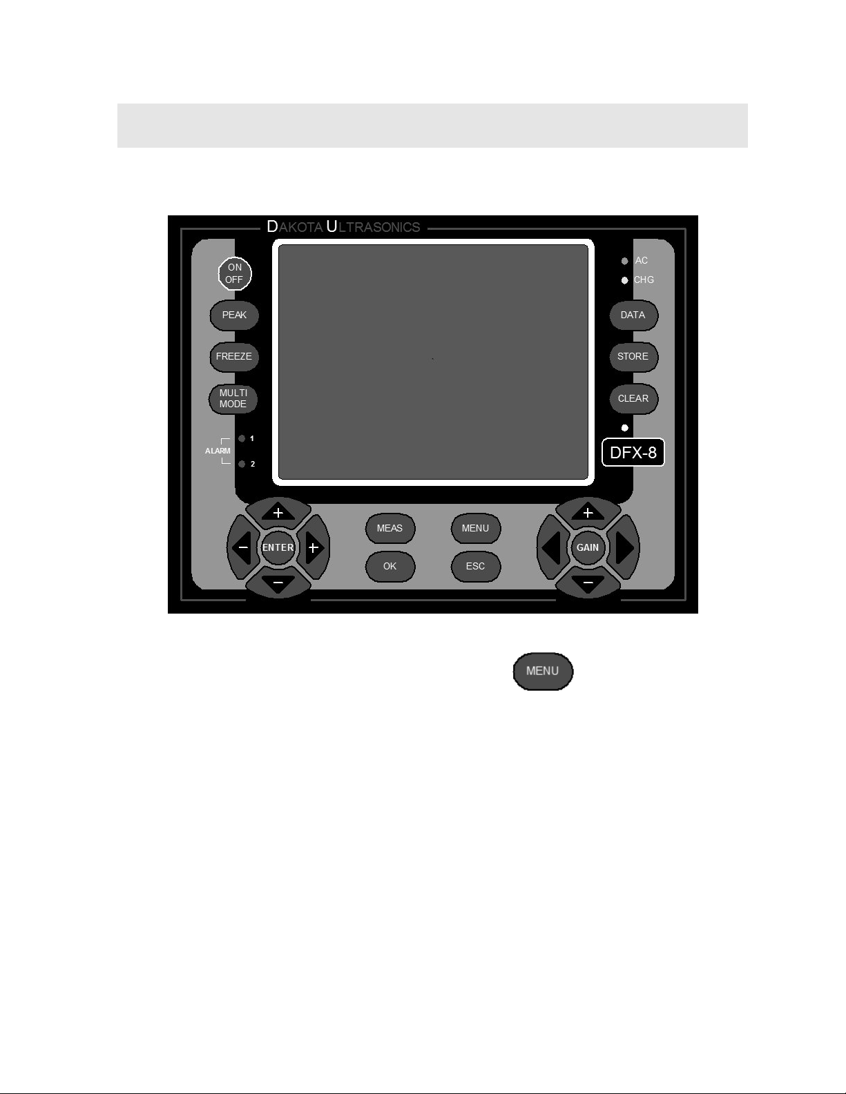
Turn the DFX-8 on and off using the switch located on the bottom right corner of the
keypad. When DFX-8 is initially turned on, a flash logo and blinking lights will be
displayed, followed by attempting to identify the transducer (probe) currently plugged
into the gauge. The DFX-8 is equipped with an “Auto Probe Recognition” feature that
attempts to identify special transducers with this built in feature. If the DFX-8 doesn’t
find a transducer equipped with this feature, the user will be advanced to a list of
transducers requiring the user to select a specific transducer type. The following
sections outline each scenario. Note: This section is primarily written as a basic
startup guide only.
2.1 DFX-8 Overview
2
Page 7
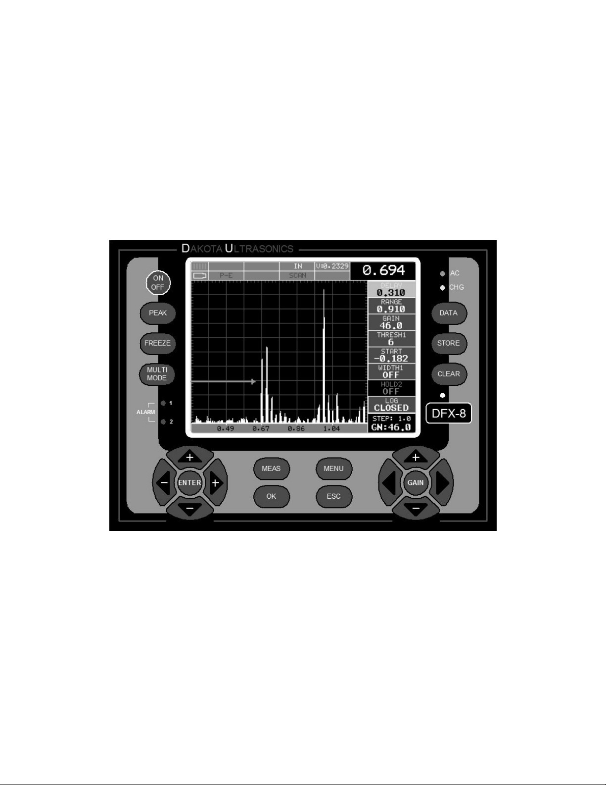
DFX-8 Ultrasonic Thickness Gauge
In order to understand how to operate the DFX-8, it’s best to start off with an
understanding of what it is we’re looking at exactly. The DFX-8 has a lot of great
features and tools that will prove to be a huge benefit for the variety of applications
you’re constantly facing on a continual basis. Let’s have a brief look at the screens
you’ll be looking at most often:
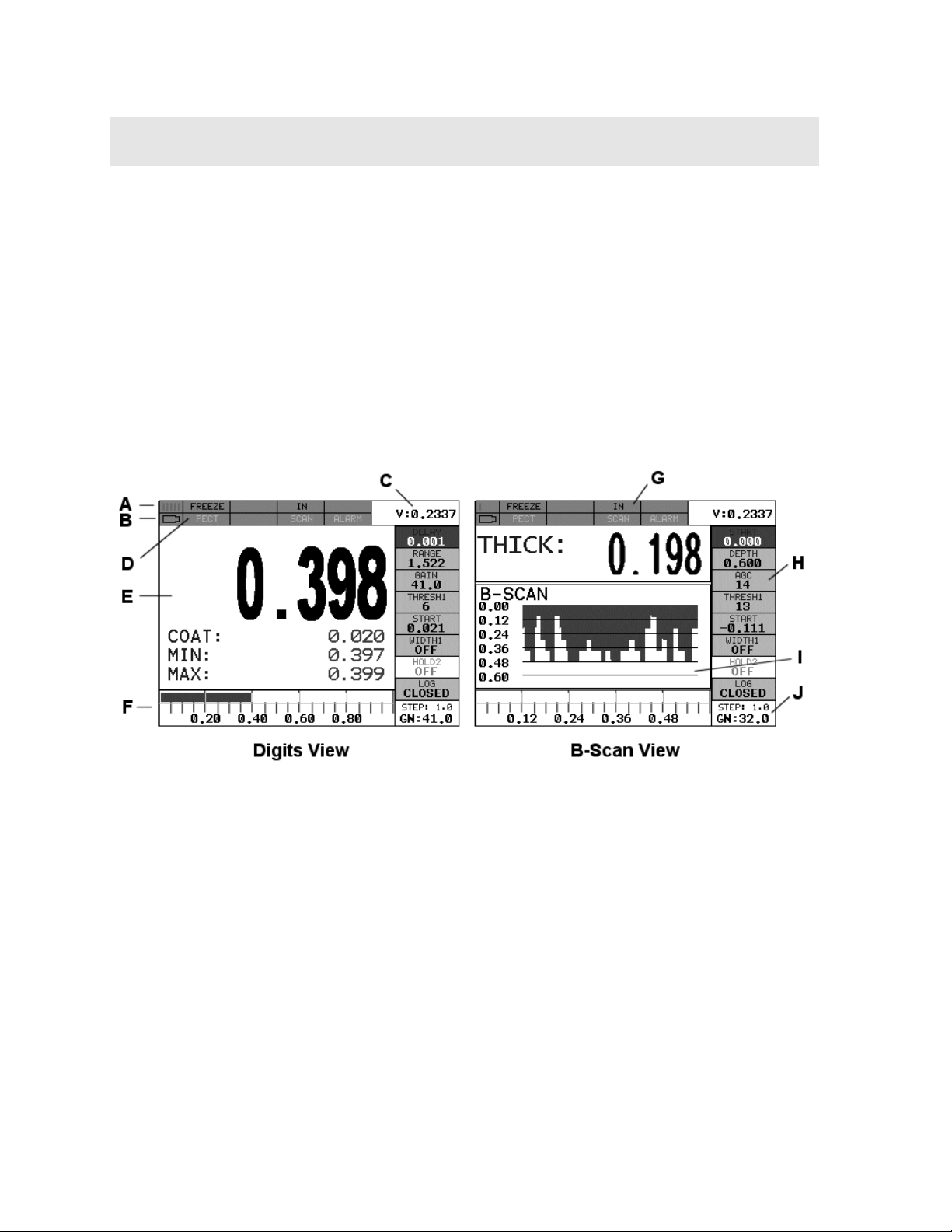
A. Repeatability/Stability Indicator – This indicator should be commonly used
in conjunction with the digital thickness values displayed. When all the vertical
bars are fully illuminated and the last digit on the digital thickness value is
stable, the DFX-8 is reliably measuring the same value 3 to 200 times per
second, depending on which measurement mode and features are enabled.
B. Battery Icon – Indicates the amount of battery life the DFX-8 has remaining.
C. Velocity – The material velocity value the DFX-8 is currently using or
calibrated for. Displayed in both English or Metric units, depending on the
what units the gauge is set for.
D. Feature Status Bar – Indicates the features currently enabled and in use in
the following order:
Measurement Mode
Differential Mode
High Speed Scan Mode
Alarm Mode
Gain Setting
E. Digital Material Thickness Values – Depending on the measurement mode
selected, the base material and coating thicknesses are displayed. If the scan
feature is enabled, the minimum and maximum thickness value of the base
material is displayed and updated simultaneously during the scan .
3
Page 8
Dakota Ultrasonics
F. Scan Bar – Another view of material thickness in a deflection style horizontal
bar. This is a visual tool that would enable the user the ability to see thickness
changes during high speed scans from flaws and pits.
G. Units – The current measurement units being used (English, Metric).
H. Hot Menu items – We call this menu section our “hot menu”, as these items
are the most commonly adjusted features, requiring quick access from the
user. They can be displayed and scrolled by pressing the MEAS key at any
time. The MEAS key advances forward and the ESC key backwards to the
next hot menu item. Alternatively, the UP,DOWN, LEFT and RIGHT arrow
keys on the left button wheel can be used to either scroll through the sub
menu items, or advance to the next HOT MENU items list. There are 8 HOT
MENU lists, that contain the most commonly adjusted items from the tabbed
menus, and in the same order as the tabbed menus. Note: Some of the lists
contain multiple tabbed menus in order to condense the number of HOT
MENU lists.
I. B-Scan Display – Cross section view of the material. Provides the user with
graphical view of the opposite/blind surface (i.e. inside pipe wall surface), to
give the user some idea of the condition, or integrity of the material being
tested.
J. Gain & Step Size – The gain and increment step size can be continuously
used and adjusted at any time using the UP and DOWN arrow keys on the
right button wheel to scroll the value, and the GAIN key to activate the Digit
Edit screen to adjust the step size.
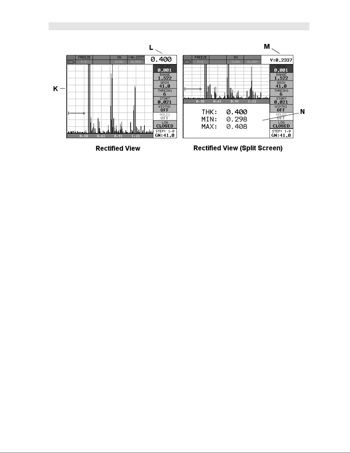
K. Rectified A-Scan Display – The actual sound wave reflection that is returned
from the detection of the opposite surface of the material being measured. In
this view, only half of the sine wave is being displayed (positive or negative).
This view is commonly referred and used as a “flaw detection” mode.
L. Reference Note – When a full screen sound wave is being displayed, the
material thickness value is displayed here.
M. Reference Note – In a split screen mode the material velocity is displayed
here.
N. Split Screen Display – This display option ‘splits’ the screen in half,
displaying the waveform/B-Scan and the thickness values concurrently.
4
Page 9
DFX-8 Ultrasonic Thickness Gauge
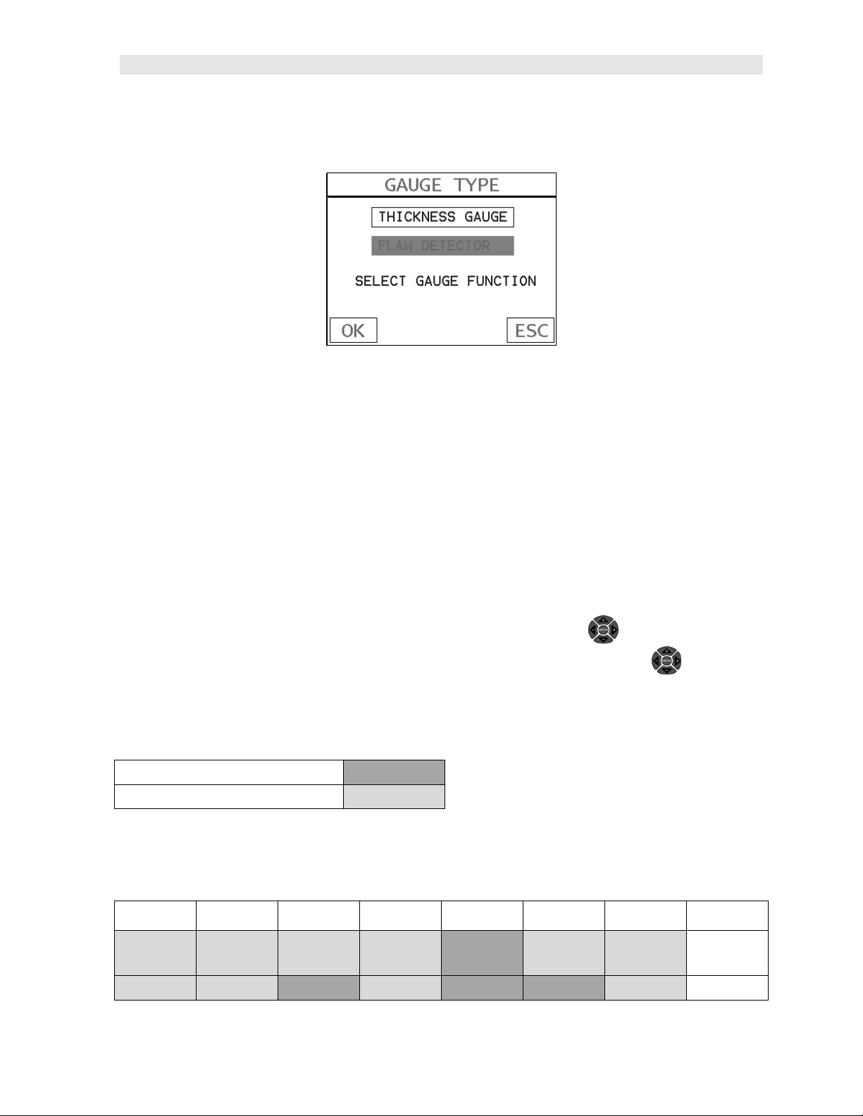
2.2 Gauge Type
Power up the DFX-8, by pressing the on/off key located in the bottom right corner of
the keypad. During initial boot up, a flash screen and lights will be displayed,
followed by a GAUGE TYPE selection screen. Since this manual will focus on the
thickness gauge portion of the DFX-8, use the UP/DOWN arrow keys to select
“thickness gauge”, followed by pressing the OK key start the DFX-8 in thickness
mode.
2.3 Top & Submenu Reference
The following table is a quick menu reference guide. The DFX-8 has 15 top level
menu titles, and multiple submenu items as illustrated below. The DFX-8 also has 8
‘hot menu’ subsets of the same menu structure. These are the most commonly
adjusted submenu items from each of the top level menus. They can be quickly
accessed from the main measurement screen by pressing the LEFT and RIGHT
arrow keys multiple times using the left button wheel, and pressing the UP and
DOWN arrow keys on the left button wheel to select the appropriate submenu item.
Refer to Chapter Three for additional definitions and information on the keypad and
menu items.
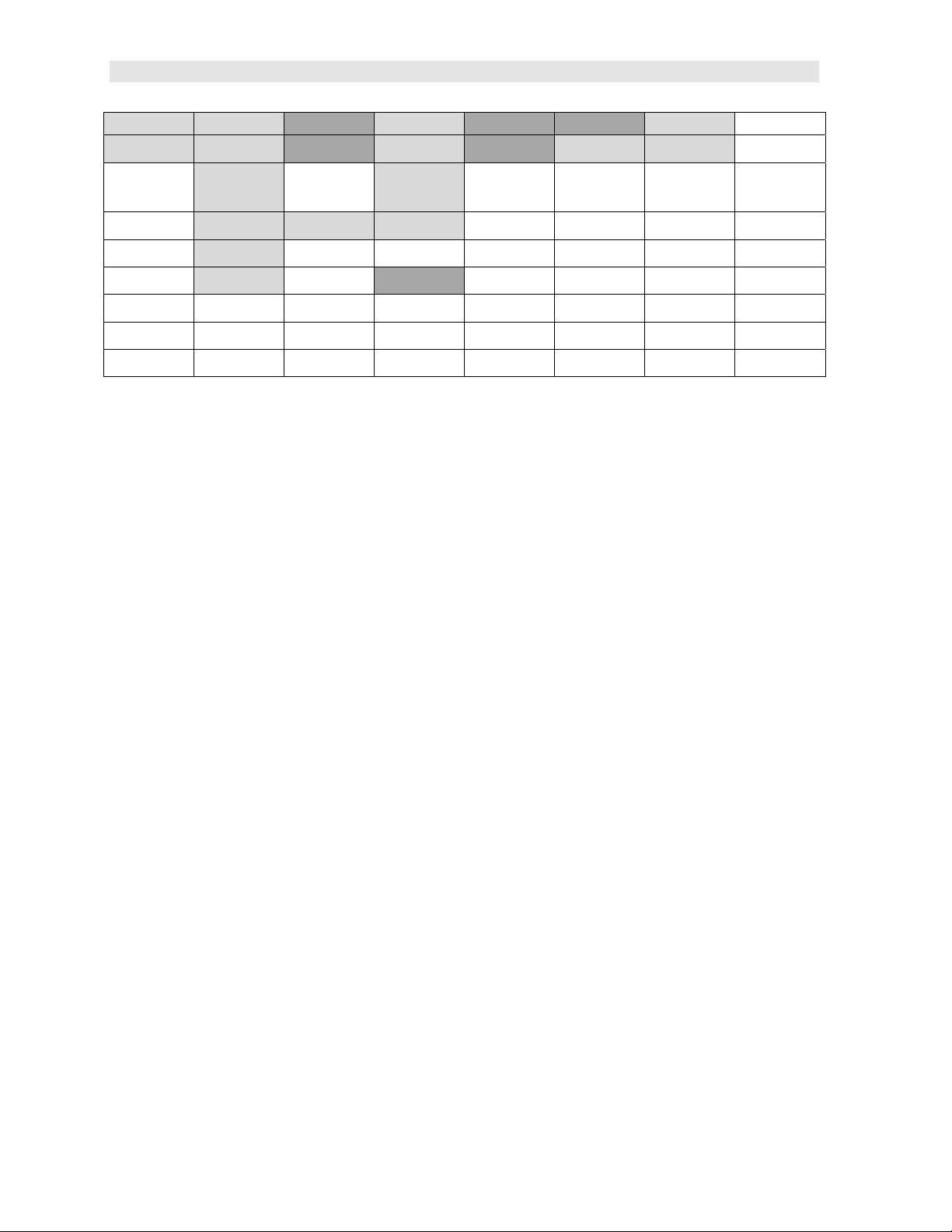
1st Main Hot Menu
Additional Hot Menus
Note: “Log” is also listed in the 1st main Hot Menu, and is used to access data storage if no log file is
currently open, or display log or grid file if open.
Start >>
PRB CAL DISP TUNE GT1 GT2 GT3 SETUP
ZERO PROBE MAT VIEW MEASURE
MODE
ZERO MATL 1PT DELAY POLARITY GATE1 WIDTH HOLDOFF 2 HOLDOFF 3 SAVE
START GATE2 WIDTH GATE3 WIDTH OPEN
5
Page 10
Dakota Ultrasonics
COATING
TYPE MATL 2PT RANGE PULSE THRESHOLD 1 THRESHOLD 2 THRESHOLD 3 DELETE
VELOCITY B-SCAN
SPEED
COATING 1PT UNITS DAMPING
COATING 2PT BRIGHTNESS GAIN LANGUAGE
COATING VEL COLORS AGC
DIM
RECT WAVE
DETECT MARK
PULSER
VOLTAGE
DEFAULT
SETUP
6
Page 11
>> End
DATA UTILS XFER
NEW AUTO FIND BACKUP
SETUPS
EDIT SCAN MODE COPY DATA
OPEN ALARM COPY
SCREENS
CLOSE ALARM HIGH UPGRADE
GAUGE
DFX-8 Ultrasonic Thickness Gauge
DELETE ONE
FILE
DELETE ALL
DATA
GAUGE ABOUT
ALARM LOW CAPTURE TO
FILE
DIFFERENTIAL STORAGE
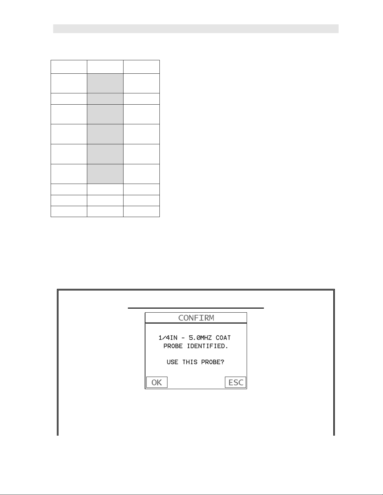
2.4 Auto Probe Recognition
When the DFX-8 is initially powered up, the gauge will automatically check to see if
the transducer plugged into the gauge can be recognized. The steps that follow
assume the DFX-8 recognized the probe type:
Probe Automatically Recognized
1) Press the OK key once to use the identified probe, or ESC to display a list of
optional transducers. Note: if the DFX-8 recognizes a specific transducer,
the user should always select OK to use the identified probe. The only time
7
Page 12
Dakota Ultrasonics
an alternative probe should be selected from a list is if the user switched
probes following initial power up and recognition.
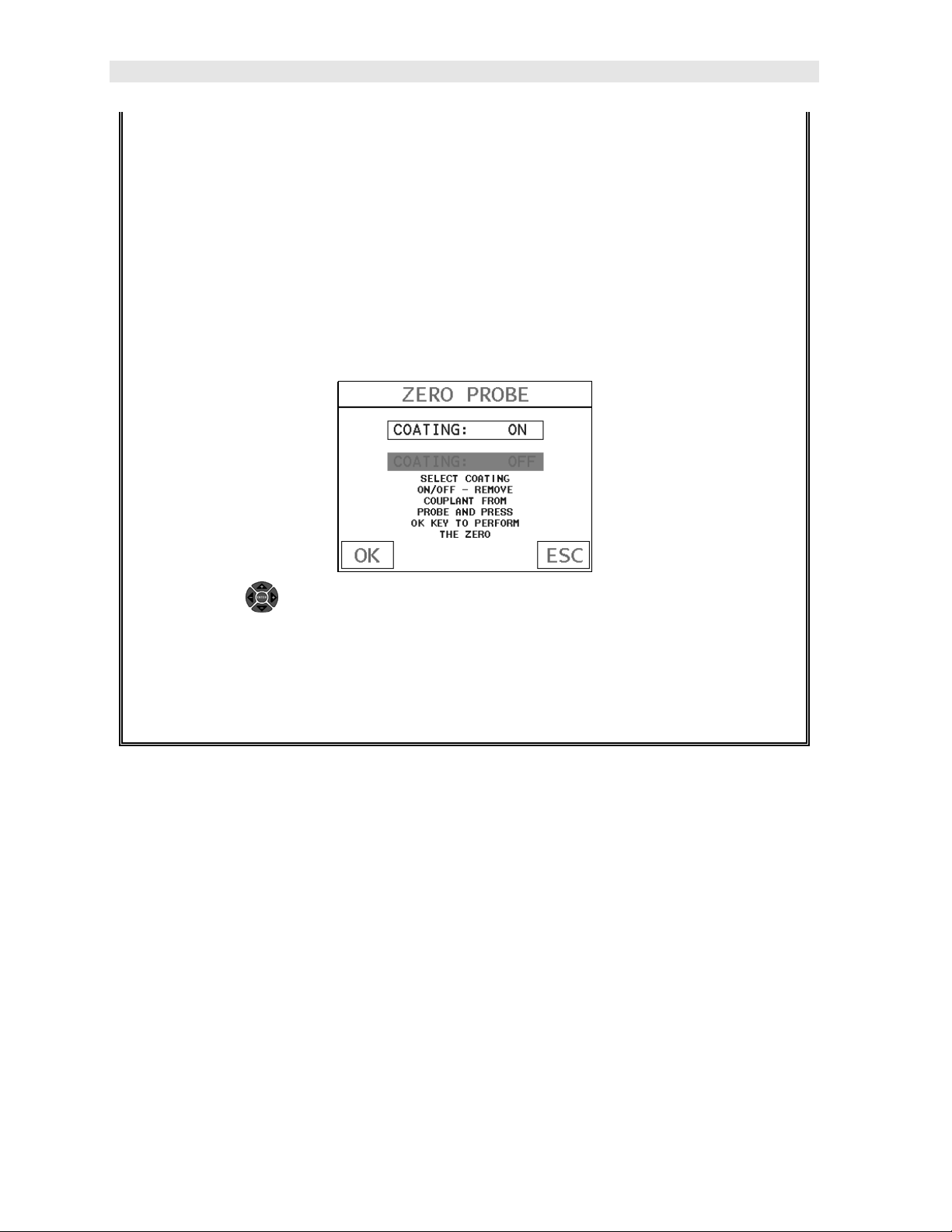
2) Assuming the DFX-8 recognized the probe and the OK key was pressed,
the DFX-8 will advance to a Zero Probe menu. If the transducer was
identified as a special transducer capable of measuring coating thickness, a
menu will be displayed allowing the user the ability to toggle the coating
thickness display on/off as follows:
3) Press the UP and DOWN arrow keys on the left button wheel to toggle
the coating option on/off.
4) Wipe all couplant from the transducer face and advance to the Probe Zero
& Calibration section outlined below.
2.5 Selecting the Transducer Type
If the DFX-8 does not identify a specific transducer type on initial power up, the user
will be required to select a type from a predefined list of types by diameter and
frequency. By selecting a transducer type from a predefined list, the DFX-8 can
recall specific properties about the transducer. Note: Once the transducer has been
selected, the DFX-8 will store and recall this transducer type every time the DFX-8 is
powered on/off. The type will only change if the user physically selects another
transducer type from the list, or selects a previously saved setup. However, the DFX-
8 will continue to take you through these steps each time the gauge is powered up.
You’ll notice that the probe type previously selected will be highlighted every time the
probe type screen is displayed. Use the following steps to select your transducer
type:
8
Page 13
DFX-8 Ultrasonic Thickness Gauge
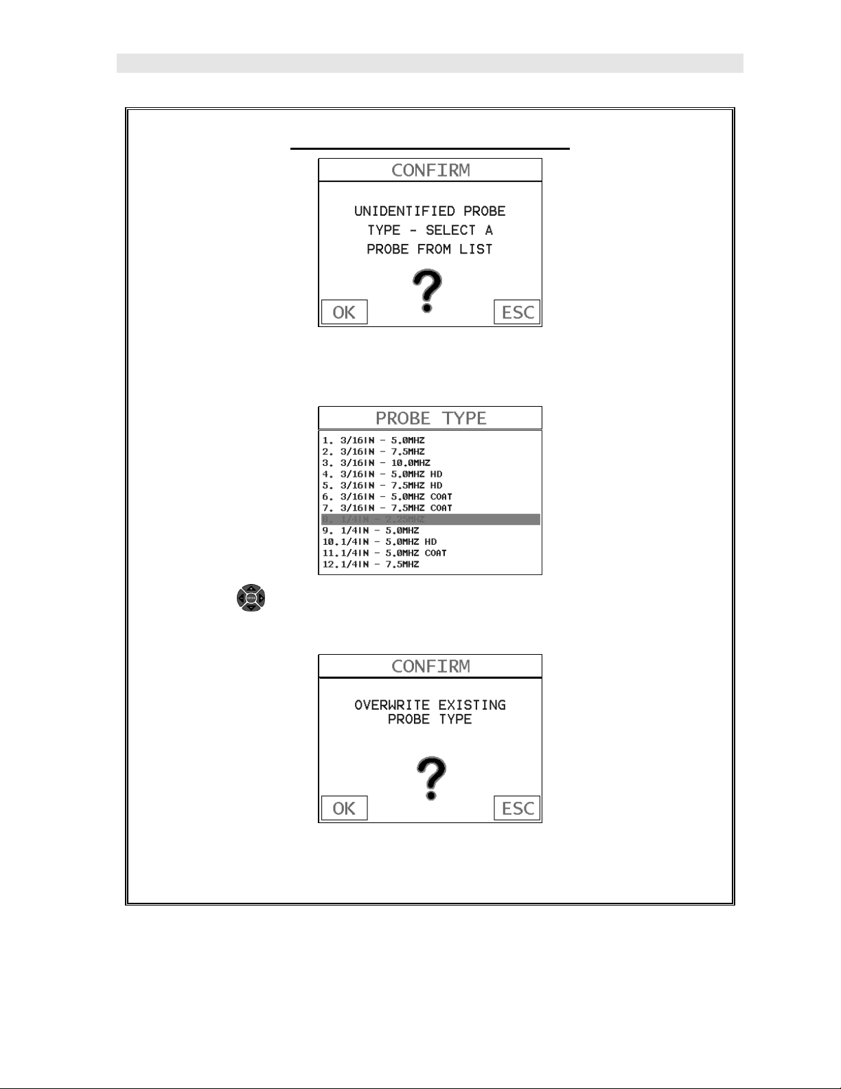
Selecting the Transducer Type
1) Press the OK or ESC keys to display the factory list of transducer types (by
diameter and frequency).
2) Press the UP and DOWN arrow keys on the left button wheel to scroll
through the transducer list until the appropriate type is highlighted.
3) Press the ENTER key to select the transducer type and display overwrite
existing probe screen.
9
Page 14
Dakota Ultrasonics
4) Press the OK key to overwrite the existing probe type with the newly
selected probe type. The zero probe screen will be displayed. Proceed to
the zero probe section that follows.
2.6 Probe Zero & Calibration
The next steps are to perform a probe zero and calibrate the DFX-8 to the material
and transducer being used. If the sound velocity is unknown, the DFX-8 can be
calibrated to a known thickness sample. This demo will briefly explain both of these
techniques.
The DFX-8 is equipped with two zero options:
1) Off Block Zero (Automatic Probe Zero) – When this feature is enabled the
DFX-8 will do an electronic zero automatically, eliminating the need for a zero
disk or block.
2) On Block Zero (Manual Probe Zero) – When this feature is enabled the
transducer must be placed on the probe zero disk (battery cover located on the
top of the unit.
Note: Transducers of the same type will have very slight mechanical and electrical
variations. If it’s discovered that the linearity is off following an initial auto probe zero
and extreme accuracy is required, a manual zero should be performed followed by an
auto zero. This will adjust and eliminate any error. This is only required if it’s
discovered the transducer is non-linear following an initial auto probe zero.
The procedures are outlined as follows:
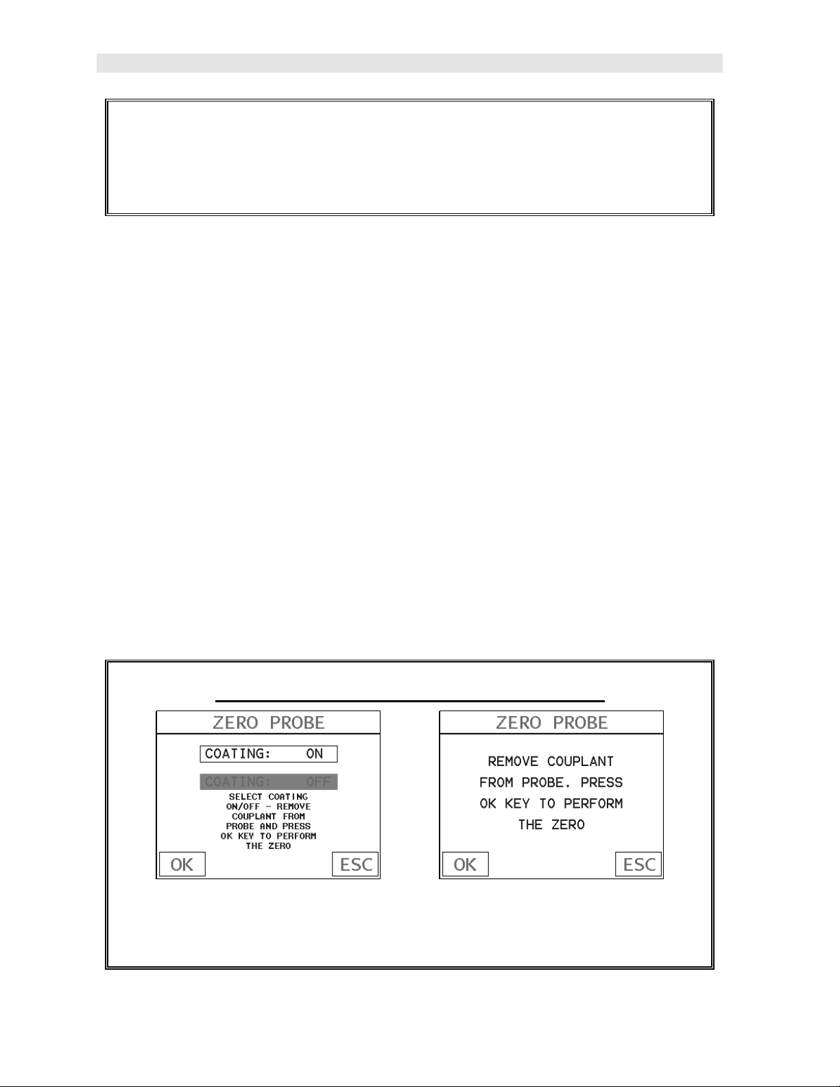
Performing an Auto Probe Zero (Off Block)
Coating Probe Identified Coating Probe Not Identified
1) Be sure all couplant has been removed from the face of the transducer.
10
Page 15
DFX-8 Ultrasonic Thickness Gauge
2) Press the OK key to perform the automatic probe zero, or ESC key to
cancel the zero operation.
3) The screens illustrated above will be briefly displayed followed by the main
measurement screen. The DFX-8 is ready to be calibrated.
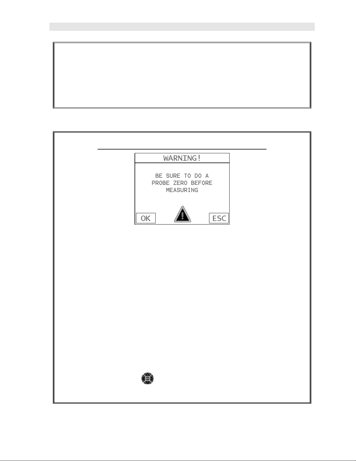
Performing a Manual Probe Zero (On Block)
Note: When the zero probe option is set to manual, the probe zero disk
(battery cap) located on the top of the gauge, will be used as a zero standard
and the warning screen illustrated above will be displayed.
1) Press the OK or ESC keys to enter the main measurement screen and
begin the manual zero process.
2) Apply a drop of couplant on the transducer and place the transducer in
steady contact with the probe zero disk, and obtain a steady reading.
3) Press the MENU key once to activate the menu items tab. Press the MENU
key multiple times to tab right and the ESC key multiple times to tab left until
the PRB menu is highlighted and displaying the submenu items.
Alternatively, press the LEFT and RIGHT arrow keys multiple times
using the left button wheel to scroll the tabbed menus.
11
Page 16
Dakota Ultrasonics
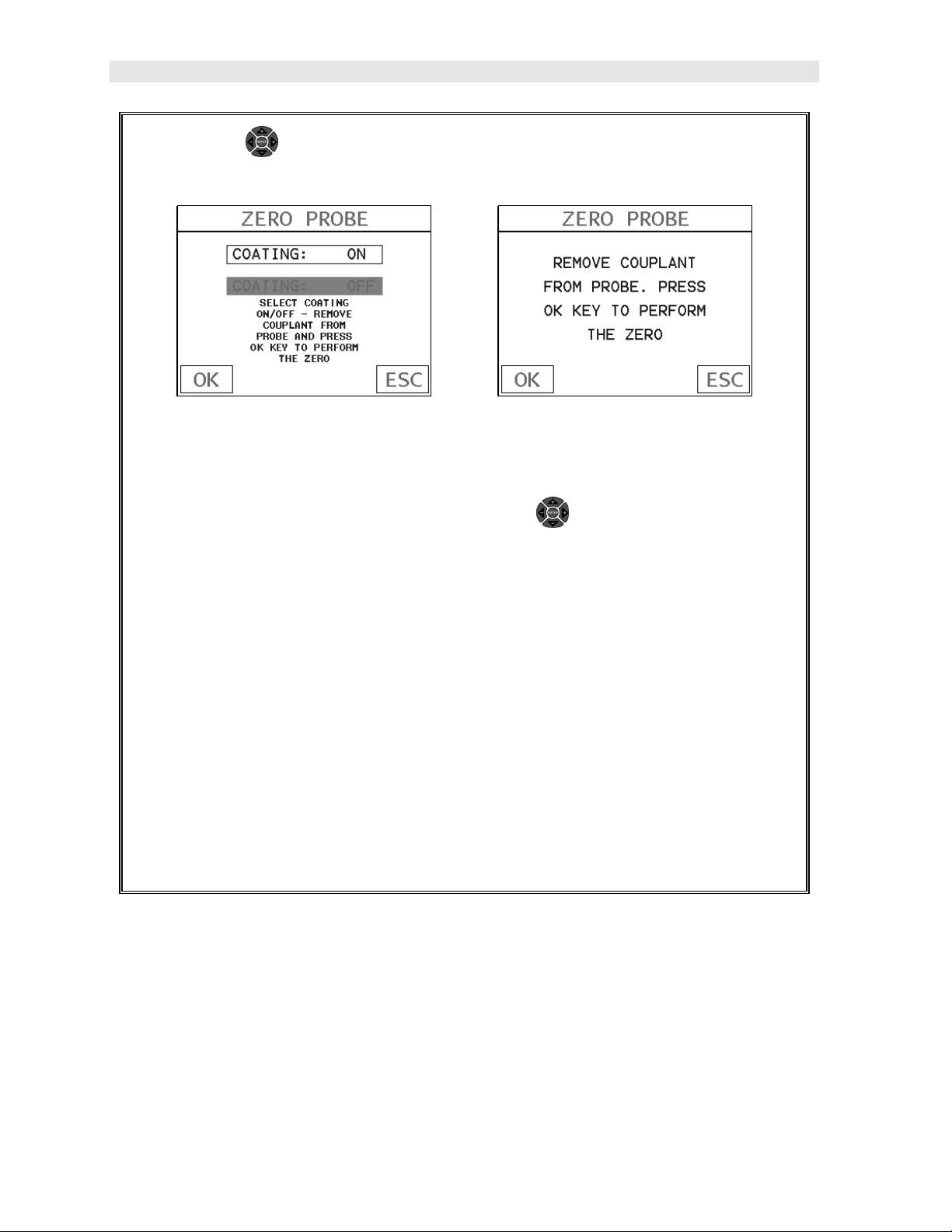
4) Press the UP and DOWN arrow keys on the left button wheel to scroll
through the sub menu items until ZERO PROBE is highlighted.
Coating Probe Identified Coating Probe Not Identified
5) Press the ENTER key to display the confirmation screen.
6) If a coating transducer was identified use the UP and DOWN arrow
keys on the left button wheel to toggle coating on/off.
7) Press the OK key to complete the probe zero function, or ESC key to cancel
the probe zero function.
8) Remove the transducer from the probe zero disk, and proceed to the
calibration section.
Note: The value that is displayed will change depending on the current velocity
setting in the DFX-8. Disregard the number that is displayed. It is not
important. What is important is accurately performing the steps outlined above
to insure reliability of the probe zero calculation.
One Point Material Calibration
For the purposes of this quick start section, we’ll only be covering the most common
one point calibration option to determine the sound velocity of the test material. It
would be very handy to carry a set of mechanical calipers to use in conjunction with
the DFX-8 for calibration in the field:
12
Page 17
DFX-8 Ultrasonic Thickness Gauge
Using a Known Thickness
Note: Be sure that the probe zero procedure has been performed prior to
performing this calibration procedure.
1) Physically measure an exact sample of the material or a location directly on
the material to be measured using a set of calipers or a digital micrometer.
2) Apply a drop of couplant on the transducer and place the transducer in
steady contact with the sample or actual test material. Be sure that the
reading is stable and the repeatability indicator, in the top left corner of the
display, is fully lit and stable. Press the MENU key once to activate the
menu items tab. Press the MENU key multiple times to tab right and the
ESC key multiple times to tab left until the CAL menu is highlighted and
displaying the submenu items. Alternatively, press the LEFT and
RIGHT arrow keys multiple times using the left button wheel.
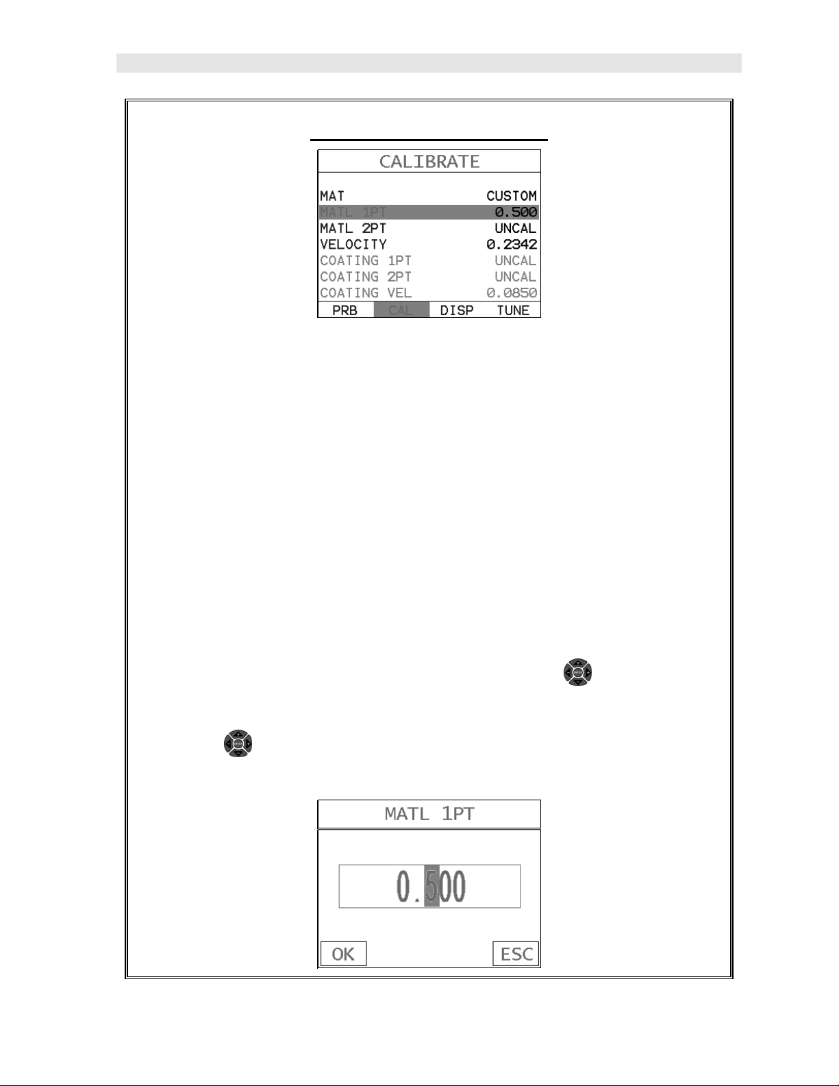
3) Use the UP and DOWN arrow keys on the left button wheel to scroll
through the sub menu items until MATL 1PT is highlighted.
13
Page 18
Dakota Ultrasonics
4) Press the ENTER key to display the Digits Edit Box.
5) Press the UP and DOWN arrow keys on the left button wheel to scroll
the highlighted value.
6) Press the LEFT and RIGHT arrow keys on the left button wheel to scroll
the digit locations.
7) Repeat steps 5 & 6 until the known thickness value is correctly displayed.
8) Press the OK key to calculate the velocity and return to the menu screen, or
ESC to cancel the one point calibration.
9) Finally, press the MEAS key to return to the measurement screen and begin
taking readings.
Note: CHECK YOUR CALIBRATION! Place the transducer back on the
calibration point. The thickness reading should now match the known
thickness. If the thickness is not correct, repeat the steps above.
2.7 Zero Coating
In order to account for very slight electronic differences in transducers of the same
type, frequency, and diameter, the DFX-8 has been equipped with a “zero coating”
feature. This enables the DFX-8 to obtain very accurate readings on coatings,
eliminating potential errors incurred from slight differences in the manufacturing
processes. The procedure is outlined below:
Performing a Coating Zero
14
Page 19
DFX-8 Ultrasonic Thickness Gauge
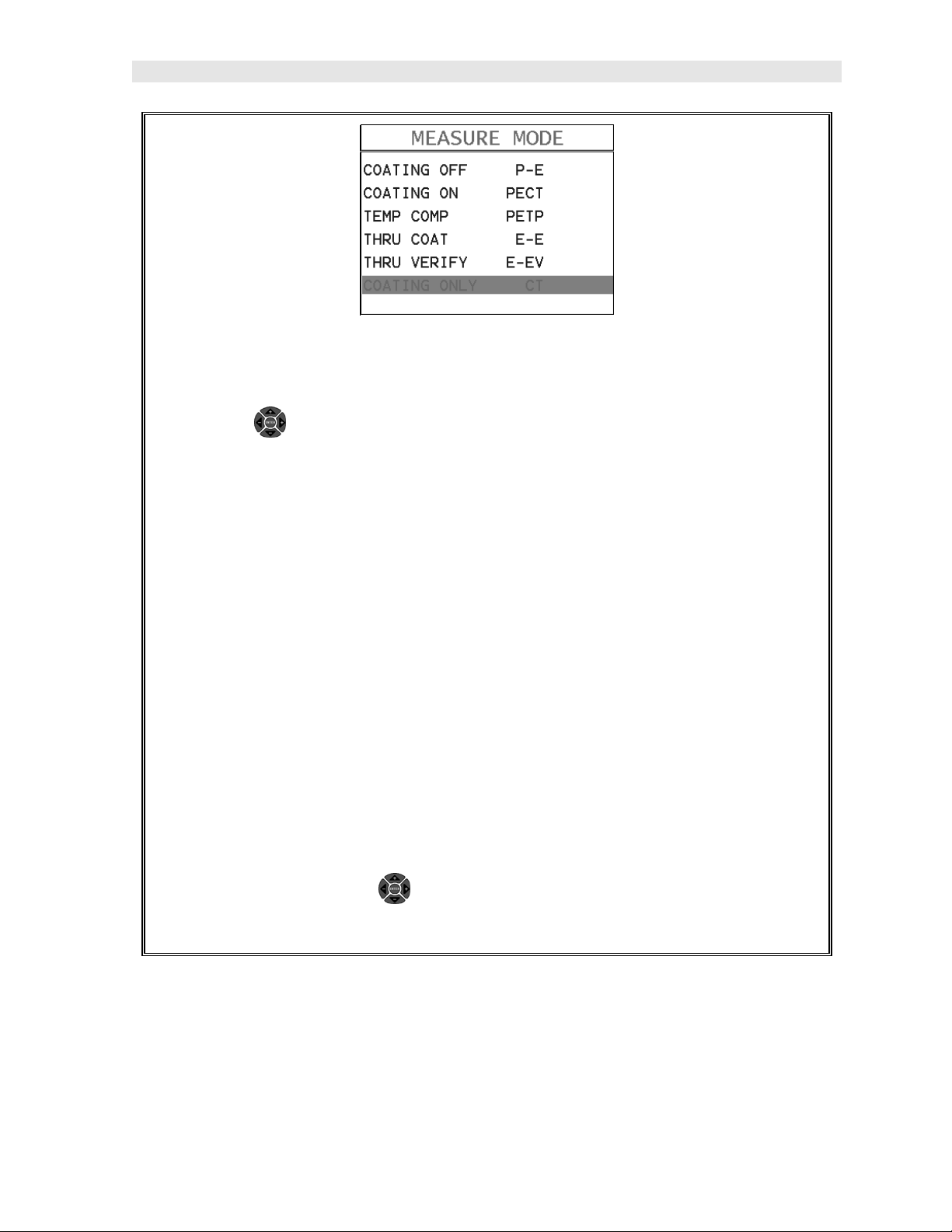
1) Press the MULTI MODE key once to activate the measurement mode
options.
2) Use the UP and DOWN arrow keys on the left button wheel to scroll
through the sub menu items until Coating Only (CT) mode is highlighted.
3) Press the MEAS key to select the measurement mode and return to the
measurement screen.
4) Apply a drop of couplant on the transducer and place the transducer in
steady contact with one of the probe zero disks (emergency battery covers)
and obtain a steady reading.
Note: The coating measurement displayed will potentially be a value greater or
less than 0.
5) Press the MENU key once to activate the menu items tab. Press the MENU
key multiple times to tab right and the ESC key multiple times to tab left until
the PRB menu is highlighted and displaying the submenu items.
Alternatively, press the LEFT and RIGHT arrow keys multiple times
using the left button wheel.
15
Page 20
Dakota Ultrasonics
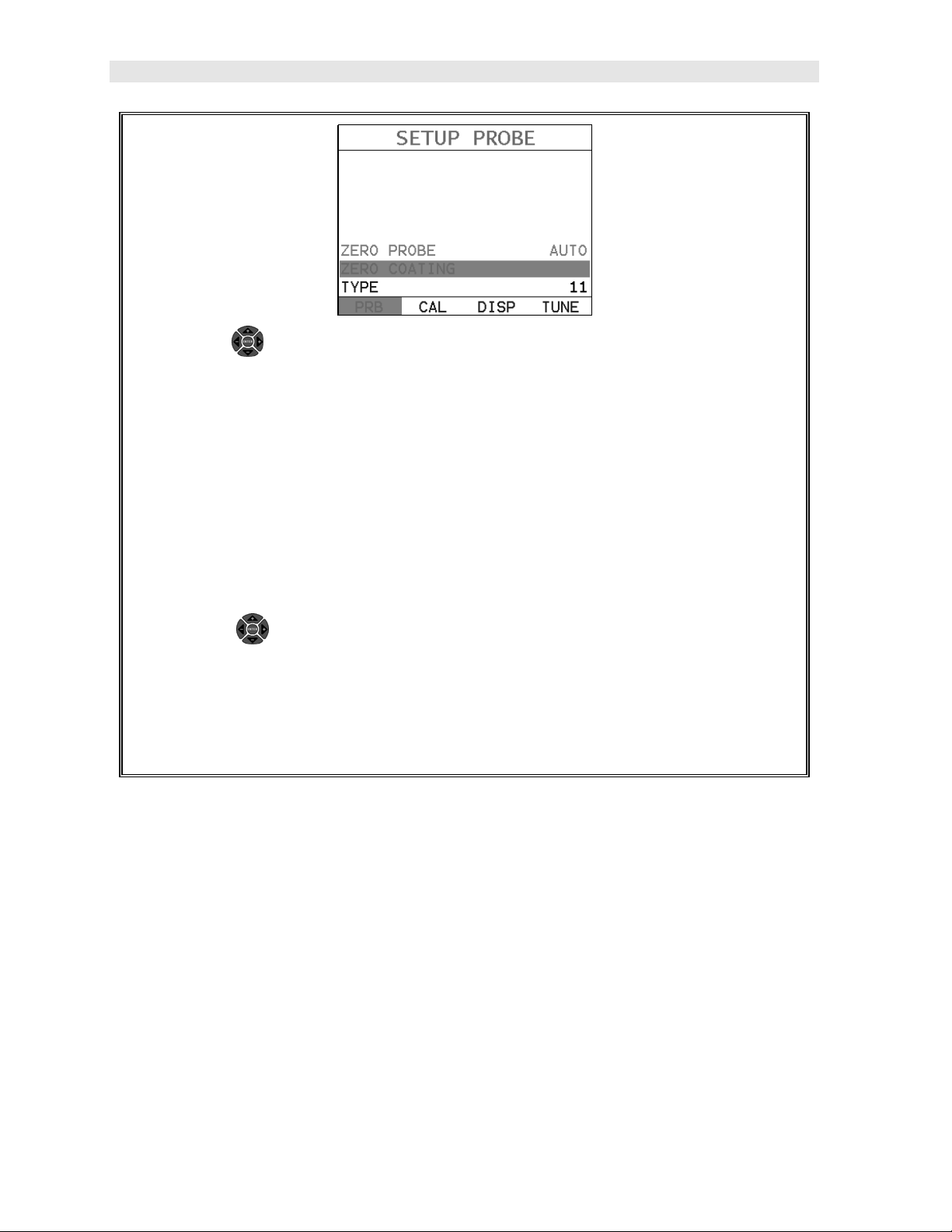
6) Use the UP and DOWN arrow keys on the left button wheel to scroll
through the sub menu items until ZERO COATING is highlighted.
7) Press the ENTER key to display the confirmation screen.
8) Press the OK key to zero the coating and return to the PRB menu, or ESC
to cancel the coating zero process.
9) Press the MULTI MODE key once to activate the measurement mode
options.
10) Use the UP and DOWN arrow keys on the left button wheel to scroll
through the sub menu items until Coating On (PECT) is highlighted.
11) Press the ENTER key to select the measurement mode and return to the
measurement screen, and begin taking readings.
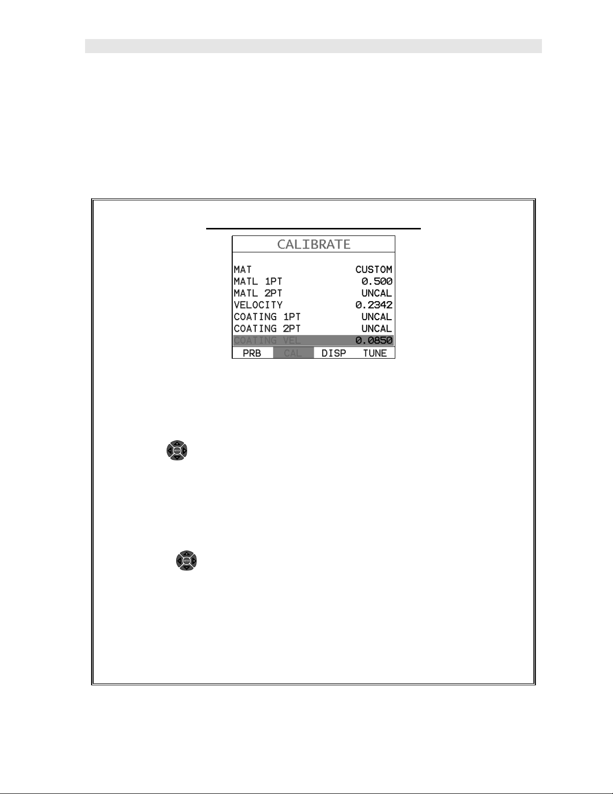
2.8 Coating Calibration
The DFX-8 has been preset to a default coating velocity of 0.0850 in/µsec (2159
m/sec). This will be very close to the most common coating material velocities used
in the field. If the velocity of the coating is known, and different than the above
default setting, the user can simply enter the coating velocity into the DFX-8.
However, if the velocity is unknown, the DFX-8 can also be calibrated to a specific
coating sample/type using the 1pt calibration option in PECT (pulse-echo coating)
mode, or a two point calibration is CT (coating only) mode. For the purpose of this
quick start section only the 1pt option PECT (pulse-echo coating) mode will be
covered. Refer to the calibration section of the manual for a complete explanation on
the coating calibration options. The following steps below outline the necessary
steps to either set the velocity of the coating, or perform a one point calibration to
calculate the coating velocity:
16
Page 21
DFX-8 Ultrasonic Thickness Gauge
Known Coating Velocity
If the coating velocity is known, the user may wish to simply enter the velocity
number into the DFX-8, rather than have the DFX-8 calculate the velocity value using
a known thickness on a coating sample. The steps for entering the velocity are
outlined below:
Using a Known Coating Velocity
1) Press the MENU key once to activate the menu items tab. Press the MENU
key multiple times to tab right and the ESC key multiple times to tab left until
the CAL menu is highlighted and displaying the submenu items.
2) Use the UP and DOWN arrow keys on the left button wheel to scroll
through the sub menu items until COATING VEL is highlighted.
3) Press the ENTER key to display the Digits Edit Box.
4) Press the UP and DOWN arrow keys to scroll the highlighted value.
5) Press the LEFT and RIGHT arrow keys on the left button wheel to
scroll the digit locations.
6) Repeat steps 4 & 5 until the velocity number is correctly displayed.
7) Press the OK key to set the coating velocity and return to the menu screen,
or ESC to cancel entering the coating velocity.
17
Page 22
Dakota Ultrasonics
8) Finally, press the MEAS key to return to the measurement screen and
begin taking readings.
Known Coating Thickness
When the exact velocity of a coating is unknown, the user has the option of
performing a one point calibration on a sample of the coating with a known thickness
to determine the sound velocity. It would be very handy to carry a set of mechanical
calipers to use in conjunction with the DFX-8 for calibration in the field:
Using a Coating Sample to Calibrate
1) Physically measure a location on a coating sample using a set of calipers or
a digital micrometer.
Important Note: In PECT (pulse-echo coating) mode, the coating sample must
be coupled to metal in order to calibrate successfully. Simply place a drop of
couplant on a piece of metal, lay the coating sample over the couplant on the
metal and proceed to step 2.
2) Apply a drop of couplant on the transducer and place the transducer in
steady contact with the coating (on metal) sample or actual test material. Be
sure that the reading is stable and the repeatability indicator, in the top left
18
Page 23
DFX-8 Ultrasonic Thickness Gauge
corner of the display, is fully lit and stable. Press the MENU key once to
activate the menu items tab. Press the MENU key multiple times to tab right
and the ESC key multiple times to tab left until the CAL menu is highlighted
and displaying the submenu items. Alternatively, press the LEFT and
RIGHT arrow keys multiple times using the left button wheel.
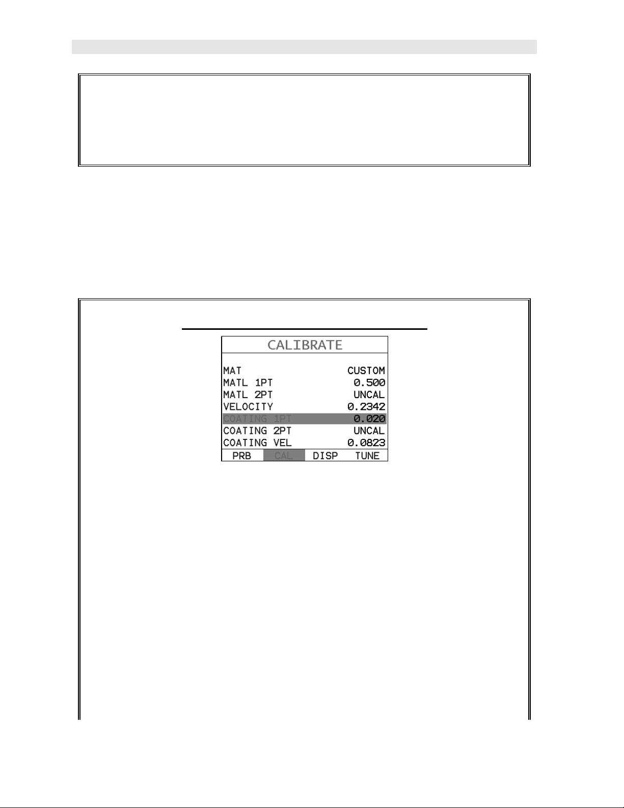
3) Use the UP and DOWN arrow keys on the left button wheel to scroll
through the sub menu items until COATING 1PT is highlighted.
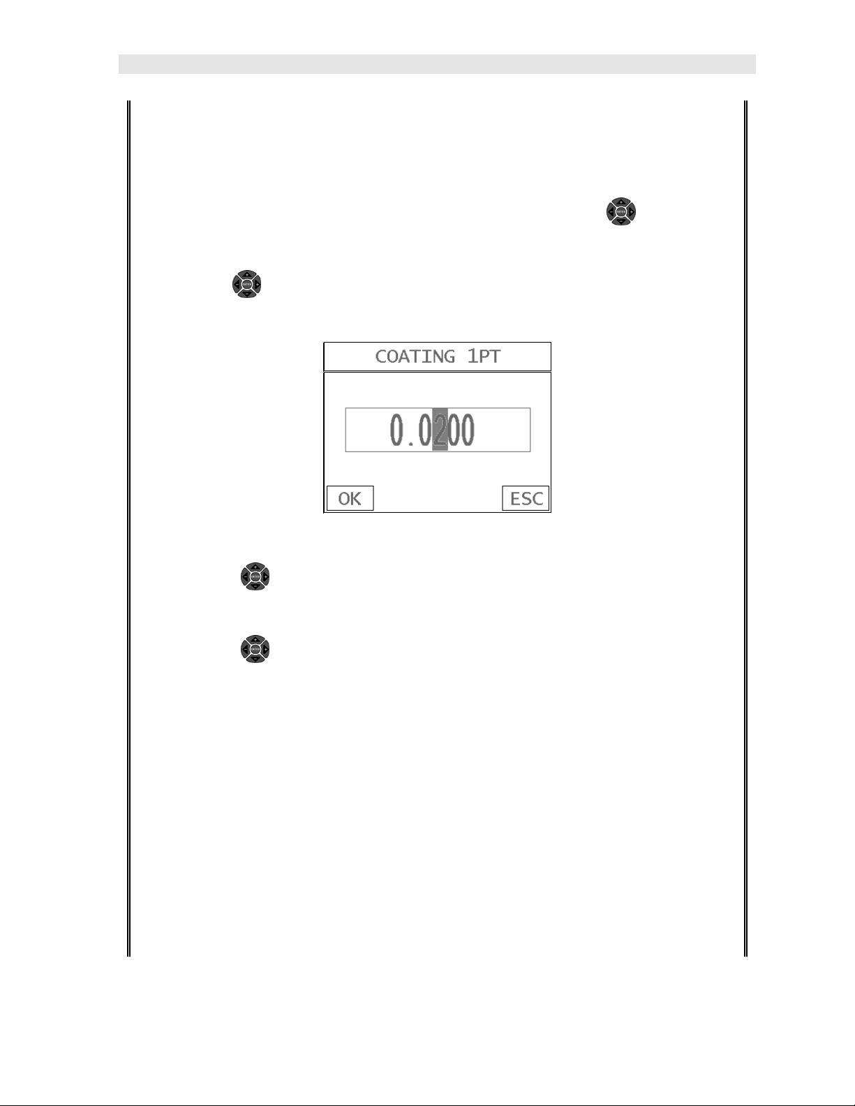
4) Press the ENTER key to display the Digits Edit Box.
5) Press the UP and DOWN arrow keys on the left button wheel to scroll
the highlighted value.
6) Press the LEFT and RIGHT arrow keys on the left button wheel to scroll
the digit locations.
7) Repeat steps 5 & 6 until the known thickness value is correctly displayed.
8) Press the OK key to calculate the coating velocity and return to the menu
screen, or ESC to cancel the one point calibration.
9) Finally, press the MEAS key to return to the measurement screen and begin
taking readings.
Note: CHECK YOUR CALIBRATION! Place the transducer back on the
calibration point. The coating thickness reading should now match the known
19
Page 24
Dakota Ultrasonics
coating thickness sample. If the thickness is not correct, repeat the steps
above.
2.9 Measure
The DFX-8 is now ready to measure. There are four different measurement view
options, each with a specific purpose – Digits, RF, RECT, & B-Scan. The steps
below outline how to toggle between the different view mode options:
Selecting the Measurement View Option
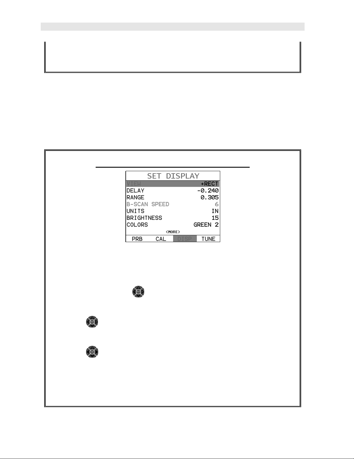
1) Press the MENU key once to activate the menu items tab. Press the MENU
key multiple times to tab right and the ESC key multiple times to tab left until
the DISP menu is highlighted and displaying the submenu items.
Alternatively, press the LEFT and RIGHT arrow keys multiple times
using the left button wheel.
2) Use the UP and DOWN arrow keys on the left button wheel to scroll the
sub menu items until VIEW is highlighted.
3) Use the LEFT and RIGHT arrow keys on the right button wheel to scroll
the view options.
4) Once the view is displayed, press the MEAS key to return to measurement
mode.
20
Page 25

DFX-8 Ultrasonic Thickness Gauge
DIGITS: Displays the digital thickness value using a large font size. This view is
useful when the DFX-8 is being used as a basic thickness gauge.
RF: Displays the actual waveform signal, much like an oscilloscope, from the
reflection of the opposite surface, pit, flaw, crack or void. This view shows both the
positive and negative peaks, and is often used to fine tune the scope settings, prior to
inspection.
RECT: Displays a half waveform signal, either positive or negative, from the
reflection of the opposite surface, pit, flaw, crack or void. The user can select the
polarity or “phase” displayed. This is typically determined by first using RF view to
select the most optimal polarity “phase”, to fine tune the scopes settings. The RECT
view is commonly used as the primary “flaw detection” view.
BSCAN: The Time Based B-Scan provides the user with a cross sectional view of
the material being tested. This mode is useful when there is concern regarding the
profile of the blind surface. This can also be a useful view when scanning for pits and
flaws.
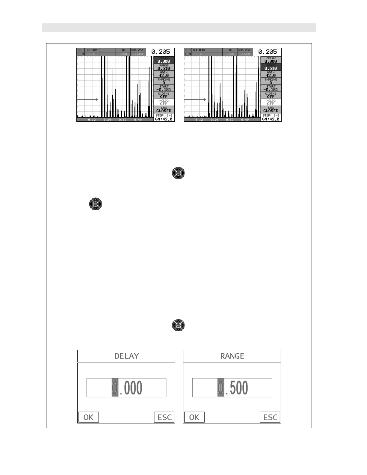
Once the view has been selected according to the application requirements, the
Delay and Range of the screen will potentially need to be adjusted, if the view has
been set to RF or RECT. Alternatively, if BSCAN was selected, the B-Start and B-
Depth settings will need to be adjusted. These settings serve the same purpose,
with only differences in terminology. The Delay the same as B-Start, and the Range
is the same as B-Depth. Therefore, these items will be grouped together for the
duration of this manual, as follows: Delay (B-Start) and Range (B-Depth). Use the
following steps to adjust these settings directly from the measurement screen as
follows:
Note: The Delay (B-Start) and Range (B-Depth) are also used to adjust the
parameters of Scan Bar.
Adjusting Delay (B-Start) & Range (B-DEPTH)
21
Page 26
Dakota Ultrasonics
1) Press the MEAS key once to activate the measure menu items. Press the
MEAS key multiple times to move right and the ESC key multiple times to
move left, until the either the DELAY (START) or RANGE (DEPTH) cell is
highlighted. Alternatively, use the UP and DOWN arrow keys on the left
button wheel.
2) Use the LEFT and RIGHT arrow keys on the right button wheel to scroll
the DELAY (START) and RANGE (DEPTH) values.
3) Repeat steps 1 & 2 until the range is correctly being displayed.
Alternatively, the DELAY (START) and RANGE (DEPTH) values can be
changed using the Digit Edit Box as follows:
4) Press the MEAS key once to activate measure menu items. Press the
MEAS key multiple times to move right and the ESC key multiple times to
move left, until the either the DELAY (START) or RANGE (DEPTH) cell is
highlighted. Alternatively, use the UP and DOWN arrow keys on the left
button wheel.
22
Page 27

DFX-8 Ultrasonic Thickness Gauge
1) Press the ENTER key to display the digits edit box.
2) Press the UP and DOWN arrow keys to scroll the highlighted value.
3) Press the UP and DOWN arrow keys on the left button wheel to scroll
the digit locations.
4) Repeat steps 2 & 3 until the DELAY (START) or RANGE (DEPTH) value is
correctly displayed.
5) Press the OK key to set the DELAY (START) and WIDTH (DEPTH) value
and return to the measure screen, or ESC to cancel entering the DELAY
(START) or WIDTH (DEPTH) value.
6) Finally, press the MEAS key to return to the measurement screen and begin
taking readings.
Note: The DELAY (START) & WIDTH (DEPTH) can also be adjusted from the
tabbed menu item DISP. However, using the hot menu keys is the easiest
method.
23
Page 28
Dakota Ultrasonics
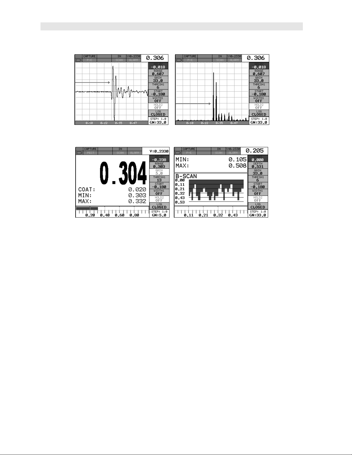
RF View Rectified (RECT) View
In the upper left corner of each of the display photos above, is the repeatability
indicator. The repeatability indicator is represented by six vertical bars and
represents how repeatable the measurements are. In regular measurement mode,
the DFX-8 makes 8 measurements a second. In scan mode, the DFX-8 makes 200
measurements a second. If the coating mode option is activated, the DFX-8 makes 3
measurements a second in regular measurement mode and 65 measurements a
second in scan mode. When the DFX-8 is idle, only the left vertical bar will be
displayed. However, when the DFX-8 is making a measurement, four or five of the
bars should be displayed on the repeatability indicator. If fewer than four bars are
showing, the DFX-8 is having difficulty achieving a stable measurement and the
thickness value displayed is potentially unstable.
Digits View B-Scan View
24
Page 29
CHAPTER THREE
KEYBOARD, MENU, & CONNECTOR REFERENCE
3.1 Menu Key (Operation & Sub Menus)
The Menu key activates the primary menu structure containing 10 menu tab groups.
These tab groups then contain sub menu items, or functions. The sub menu items
have been organized in tab groups according to how closely they are related to the
individual tab group names. Let’s first get familiar with how to move around in these
tabs before continuing on to the sub menu functions. This procedure is outlined
below:
25
Page 30
Dakota Ultrasonics
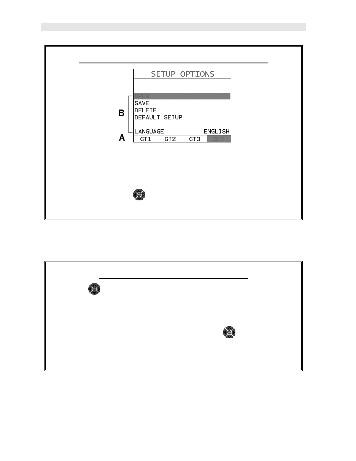
Activating and Getting Around in the Menu Items
1) Press the MENU key once to activate the menu items tab. Press the MENU
key multiple times to tab right, and the ESC key multiple times to tab left
until the desired tab group is highlighted and displaying the submenu items.
Alternatively, press the LEFT and RIGHT arrow keys multiple times
using the left button wheel. The tab groups are illustrated above (A).
Now that you’re familiar with activating and moving amongst the tab groups, let’s
have a look at how to move around in the sub menu items as follows:
Getting Around in the Sub Menu Items
1) Use the UP and DOWN arrow keys on the left button wheel to scroll
through the sub menu items until the desired function is highlighted. The
sub menu items are illustrated in the diagram above (B).
2) Depending on which function is highlighted, use the LEFT and RIGHT
arrow keys on the right button wheel to scroll the options, or the ENTER key
to activate the Digit Edit and List Box options.
The sections to follow will provide the user with an explanation of the sub menu
functions:
26
Page 31

DFX-8 Ultrasonic Thickness Gauge
3.2 Probe – Menu
ZERO PROBE:
micrometer is zeroed. If the DFX-8 is not zeroed correctly, all of the measurements
made using the DFX-8 may be in error by some fixed value. The DFX-8 is equipped
with an optional automatic or manual zero feature. Refer to the section on page 51,
for an explanation of this important procedure.
ZERO COATING: In order to account for very slight electronic differences in
transducers of the same type, frequency, and diameter, the DFX-8 has been
equipped with a “zero coating” feature. This enables the DFX-8 to obtain very
accurate readings on coatings, eliminating potential errors incurred from slight
differences in the manufacturing processes. Refer to the section on page 51, for a
detailed explanation.
TYPE:
transducer types. This provides increased linearity between transducers. Refer to
page 48 for a further explanation.
Enables the user to select the type of transducer being used from a chart of
The DFX-8 is zeroed in much the same way that a mechanical
3.3 CAL – Menu
MAT: Select the material velocity from a chart of basic material types when a known
sample thickness, or material velocity cannot be obtained. Refer to page 60 for
further info.
MATL 1PT:
automatically calculate the velocity by entering a known sample thickness. Refer to
page 57 for further info.
MATL 2PT: Performs a two-point calibration. This option allows the user to
automatically calculate the velocity by entering a second known sample thickness.
Refer to page 59 for further info.
VELOCITY:
material velocity. Refer to page 55 for further info.
Performs a single point calibration. This option allows the user to
Function to calibrate the DFX-8 by setting the velocity to a known
27
Page 32

Dakota Ultrasonics
COATING 1PT: Performs a single point coating calibration. This option allows the
user to automatically calculate the velocity by measuring a known coating sample
thickness. Refer to page 107 for further info.
COATING 2PT: Performs a two-point coating calibration. This option allows the
user to automatically calculate the velocity by entering a second known coating
sample thickness. Refer to page 107 for further info.
COATING VEL: Function to calibrate the DFX-8 to a specific coating material type
by entering a coating velocity. Refer to page 17 or page 101 for further info.
3.4 DISP (display) – Menu
VIEW: Selectable BSCAN (cross section), and DIGITS (large digits) views. Refer to
page 64 for further info.
DELAY (B-START): Provides the user the ability to change the start position of the
B-SCAN view. Refer to page 72 for further info.
RANGE (B-DEPTH): Provides the user the ability to change the overall depth of the
viewable measurement area. It functions a lot like a zoom on a camera. Refer to
page 74 for further info.
B-SCAN SPEED: Controls the speed of the time based B-Scan with an arbitrary
scale of 0-10, with 10 being the fastest scrolling speed. Default speed set at 6.
Refer to page 76 for further info.
UNITS: Toggle between English or Metric units. The readout will change from
inches to millimeters.
BRIGHTNESS:
been implemented, with the brightest setting at 20. Refer to page 118 for further info.
COLOR: Provides the user with 12 different color schemes to select from. There are
two schemes for each main color option. Refer to page 119 for further info.
DIM: Allows the user to conserve battery life by diming the display after idle for a
specific amount of time – OFF, 30, 60, 90, 120 seconds. Once dimmed, a single
press of any key will restore the screen brightness. Refer to page 121 for further info.
RECT WAVE:
the display setting is in RECT (rectified) wave mode only. Refer to page 123 for
further info.
DETECT MARK: Selectable graphics option for the point of detection on the
waveform: Line, Box, Dots, None. Offers the user a graphics preference on how
they prefer to view the detection on the waveform.
Blanview high speed color display. An arbitrary scale of 1-20 has
This option provides the user an outlined or filled view option when
28
Page 33

DFX-8 Ultrasonic Thickness Gauge
3.5 TUNE – Menu
MEASURE MODE: Toggles a variety of unique measurement modes for different
application requirements: Coating Off (P-E), Coating On (PECT), Temp Comp
(PETP), Thru Coat (E-E), Thru Verify (E-EV), Coating Only (CT). Refer to page 41
for further info.
POLARITY: The DFX-8 operates on a zero crossing detection principle. This
feature toggles which stroke of the cycle the crossing detection uses, either positive
or negative. Refer to page 125 for further info.
PULSE: The DFX-8 has an adjustable pulse width for both high penetration and
resolution applications. The pulse width refers to the duration of time the pulser is
on. The options are Spike, Thin, and Wide. Refer to page 127 for a further
explanation.
PULSER VOLTAGE: This feature offers a 50 volt cut/boost to the pulser. The
standard setting is 150 volts. This enables the DFX-8 to offer greater penetration for
difficult material types, or increased resolution on noisy materials. Refer to page 128
for a further explanation.
DAMPING: Provides the user with multiple input impedances to match the
impedance of the transducer, and optimized overall transducer performance. Refer
to page 122 for further info.
GAIN:
with the attenuator feature above. This feature is used to increase/decrease the
power or amplitude of the signal. This might easily be considered as similar to
turning the volume up or down on a stereo receiver. Refer to page 77 for further info.
AGC:
verify). The DFX-8 is equipped with an automatic gain control when operating in -E
(echo-echo), and E-EV (echo-echo verify) modes only. This feature automatically
increases/decreases the power or amplitude of the signal, to an optimal input to
output signal ratio. This might easily be considered as similar to turning the volume
up or down on a stereo receiver. Alternatively, the AGC can be manually controlled.
The DFX-8 is equipped with manual override, using an arbitrary range of 1-20 clicks.
The higher the number the better the dynamic gain range, and visa versa. Refer to
page 77 for further info.
The DFX-8 has 100dB gain range from (-30 to 70 dB), used in conjunction
This an automatic gain control used in E-E (echo-echo), and E-EV (echo-echo
29
Page 34

Dakota Ultrasonics
3.6 GT1 – Menu
GATE1: Gates allow the user to view a specific measurement range, or sections of
the waveform, and ignore others. The Gate1 feature adjusts the start of the gate,
according to time/distance. Gate 1 can be used in all pulse-echo and echo-echo
measurement modes. Refer to page 85 for further info.
GATE1 WIDTH: This feature allows the user to set the overall width of the gate, in
terms of distance, from the starting value of Gate1. Refer to page 85 for further info.
THRESHOLD1: Enables the user to set the sensitivity level of Gate1. The amplitude
of the signal must reach or exceed the threshold level before a measurement is
detected. Refer to page 85 for further info.
3.7 GT2 – Menu
GATE2 WIDTH: This feature allows the user to set the overall width of the gate, in
terms of distance, from the starting value of HoldOff2. Refer to page 85 for further
info.
HOLDOFF 2: Provides the user with the ability to delay the starting point of Gate2, a
specific distance from the first detection point found inside of the boundaries of the
Gate 1 settings. If no detection is found, the Gate1 width value is used as a starting
value for Gate2. Refer to page 85 for further info.
THRESHOLD2:
of the signal must reach or exceed the threshold level before a measurement is
detected. Refer to page 85 for further info.
Enables the user to set the sensitivity level of Gate2. The amplitude
30
Page 35

DFX-8 Ultrasonic Thickness Gauge
3.8 GT3 – Menu
GATE3 WIDTH: This feature allows the user to set the overall width of the gate, in
terms of distance, from the starting value of HoldOff3. Refer to page 85 for further
info.
HOLDOFF 3: Provides the user with the ability to delay the starting point of Gate3, a
specific distance from the first detection point found inside of the boundaries of the
Gate 2 settings. If no detection is found, the Gate2 width value is used as a starting
value for Gate3. Refer to page 85 for further info.
THRESHOLD3: Enables the user to set the sensitivity level of Gate3. The amplitude
of the signal must reach or exceed the threshold level before a measurement is
detected. Refer to page 85 for further info.
3.9 SETUP – Menu
OPEN:
These setups can be recalled and used at any time. Refer to page 158 for further
info.
SAVE:
modified or created by the user. Refer to page 160 for further info.
DELETE:
in memory. Refer to page 163 for further info.
DEFAULT SETUP:
setups in the DFX-8 have been corrupted and a computer is not accessible. Refer to
page 165 for further info.
LANGUAGE:
8. Refer to page 167 for further info.
Displays a list of factory and user defined setups currently stored in memory.
Provides the user with the ability to save a custom setup that has been
Provides the user with the ability to delete specific setups previously save
Loads a basic default setup. Use only as a last resort when the
Provides the user the ability to select different languages for the DFX-
31
Page 36

Dakota Ultrasonics
3.10 DATA – Menu
NEW: Allows the user the ability to create a new alpha numeric grid, or sequential
log file with auto identifiers. It is equipped with custom parameters, rows, and
columns depending on the user’s application reporting requirements. Refer to page
135 for further info.
EDIT: Gives the user the ability to change parameters of grid or sequential file
previously saved. Note: Pre-defined coordinates cannot be changed once they have
been created. Refer to page 152 for further info.
OPEN: This function provides the user with the ability to recall grids or sequential log
files that currently exist in memory, from a list of grids. Refer to page 154 for further
info.
CLOSE: Provides the user the ability to close a currently opened grid or sequential
log file. Refer to page 156 for further info.
DELETE ONE FILE: This function provides the user with the ability to delete one
individual grid or sequential log file from a list of multiple grids/files previously saved
in memory. Refer to page 149 for further info.
DELETE ALL DATA: This function provides the user with the ability to delete all files
currently stored in memory. Refer to page 150 for further info.
3.11 UTIL (utilities) – Menu
AUTO FIND:
the viewable display area. Refer to page 112 for further info.
SCAN MODE:
overall sample rate from 65 to 200 measurements per second, depending on the
current measurement mode used. Refer to page 112 for further info.
ALARM:
Automatically locates the detection point if the measurement is out of
This function enables a hi speed scan mode that increases the
Toggles alarm mode on, off, or audible. Refer to page 114 for further info.
32
Page 37

DFX-8 Ultrasonic Thickness Gauge
ALARM HIGH: Gives the user the ability to set the HI limit parameter. If the
measurement exceeds this value, a red light will illuminate and sound the internal
beeper. Refer to page 114 for further info.
ALARM LOW: Gives the user the ability to set the LO limit parameter. If the
measurement falls below this value, a red light will illuminate and sound the internal
beeper. Refer to page 114 for further info.
DIFFERENTIAL: Gives the user the ability to set a nominal value and the DFX-8 will
display +/- the difference from the nominal value entered. Refer to page 116 for
further info.
GAUGE: Gives the user the ability to select between the two gauge types included
in the DFX-8, thickness gauge or flaw detector. Refer to page 5 for further info.
KEY CLICK: Gives the user the ability to set the level of the key press beeper OFF,
QUIET, or LOUD. Refer to page 129 for further info.
SET DATE: Gives the user the ability to set the internal date and time stamp in the
DFX-8. Refer to page 130 for further info.
3.12 XFER (transfer) – Menu
COPY SETUPS: Copies setup files from either the internal or external SD memory
card to the other memory card, depending on the current internal/external setting of
Storage (current device being used to store data), located in the XFER menu. Refer
to page 170 for further info.
COPY DATA:
internal or external SD memory card to the other memory card, depending on the
current internal/external setting of Storage (current device being used to store data),
located in the XFER menu. Refer to page 170 for further info.
COPY SCREENS:
external SD memory card to the other memory card, depending on the current
internal/external setting of Storage (current device being used to store data), located
in the XFER menu. Refer to page 170 for further info.
CAPTURE TO FILE: Enables the user the ability to enable screen captures to .tiff
files, and used in conjunction with the FREEZE key. Refer to page 132 for further
info.
UPGRADE GAUGE: Enables the user the ability to upgrade the DFX-8 to the most
current firmware revision. Refer to page 172 for further info.
Enables the user to copy all, or individual grid/log files from either the
Copies screen capture (.tif’s) files from either the internal or
33
Page 38

Dakota Ultrasonics
STORAGE: Enables the user to select which SD memory card to use for storage.
Note: if no card exists in the external reader slot, this option will be grayed out and
inactive. Refer to page 169 for further info.
ABOUT: Provides the user with Dakota Ultrasonics contact information and the
DFX-8 software version. Refer the Dakota Ultrasonics web site for information on the
latest firmware versions available for download.
3.13 CLR (clear) Key
The primary functions of the CLR key, is to clear a measurement from a grid or
sequential log files cell location or set obstruct, and backspace in an Alpha Edit Box.
If a user has already saved a measurement and B-Scan to a cell location, use this
key to clear the measurement at any time.
3.14 MEAS (measurement mode) Key
The MEAS key puts the DFX-8 into it’s primary mode of operation. In this mode, the
user has a complete view of the LCD.
3.15 OK Key
The primary function of the OK key is confirmation of a change or selection. The OK
key also toggles the Hot Menu area, while in measurement mode, to a large digits
display area. If the DFX-8 is displaying a grid log, the OK key toggles an advance to
row number option.
3.16 ESC Key
The ESC key is used in the MENU, MEAS, and EDIT functions as a back or escape
function. If the DFX-8 is displaying a grid or sequential log, the OK key toggles the
display options: Digits, RF, RECT, and B-Scan views.
3.17 Wheel Keys
34
Page 39

DFX-8 Ultrasonic Thickness Gauge
The Wheel Keys are used to navigate through the menus, increase/decrease values,
and toggle specific function keys.
3.18 ENTER key
The ENTER key is used in the overall menu selection process, to activate list and
edit boxes, display and save measurements to grid or sequential files locations.
3.19 MULTI MODE Key
The MULTI MODE key opens a measurement mode screen, listing all the modes that
are available to the transducer specifically selected, or auto detected. The modes
can be all or a combination of the entire set of modes the DFX-8 offers, depending on
which transducer is being used as follows: Coating Off (P-E), Coating On (PECT),
Temp Comp (PETP), Thru Coat (E-E), Thru Coat Verify (E-EV), and Coating Only
(CT).
3.20 DATA Key
The DATA key opens the tabbed data menu, allowing a user to efficiently create a
new log/grid file for storage.
3.21 STORE Key
The STORE key displays the current log/grid opened in split screen mode. If no
log/grid file is open, the STORE key will open the tabbed data menu in order create a
new, or open an existing log/grid file for storage.
3.22 PEAK Key
The PEAK key is a feature used in the flaw detector portion of the DFX-8, and is not
used in the thickness gauge.
3.23 FREEZE Key
35
Page 40

Dakota Ultrasonics
The FREEZE key is used to freeze the display for evaluation/review of what’s
currently on the display. It is also used in conjunction with the CAPTURE feature to
save the current display to a .tif (tagged image) graphic file that can be opened using
any graphics viewer.
3.24 ON/OFF Key
The ON/OFF key simply powers the unit either ON or OFF. Note: Unit will
automatically power off when idle for 5 minutes. All current settings are automatically
saved prior to powering off.
3.25 Navigating the Hot Menus
The diagram above is a screenshot of all 8 “Hot Menus” in the DFX-8. The Hot
Menu’s contain all the most regularly adjusted features from each tabbed menu, in
the exact order of the tabbed menus themselves. Some of the menus have been
combined into a single Hot Menu, in order to reduce the number of Hot Menus (i.e.
GT1 & GT2 have been combined into a single Hot Menu). The primary purpose of
the design was to provide the user with an efficient way to make adjustments on the
fly, while continuing to have visibility of the A-Scan display. The following procedure
outlines the steps to navigate and make adjustments as follows:
Navigating Hot Menus
1) Using the left button wheel, press the LEFT and RIGHT arrow keys to
scroll through the 8 individual Hot Menus, and the UP and DOWN
36
Page 41

DFX-8 Ultrasonic Thickness Gauge
arrow keys to scroll through the Hot Menu items. Alternatively, the MEAS &
ESC keys can be used to scroll through the Hot Menu items.
2) Press the LEFT and RIGHT arrow keys multiple times on the right
button wheel to toggle the value or status.
Note: This is a coarse adjustment. It’s the fastest and easiest way to
increment, decrement, or toggle the status however it does so in coarse steps.
Pressing the ENTER key will allow the user to enter a specific target value.
This procedure above is universal for navigating through and selecting all
the features in the Hot Menus.
37
Page 42

3.26 Top & Bottom End Caps
The top & bottom end panels are where all connections are made to the DFX-8. The
diagram above shows the layout and description of the connectors:
Transducer Connectors
Refer to Diagram: The transducer connectors, emergency battery backup
channels/probe zero disks, power connector and auxiliary connector are located on
the DFX-8’s top end cap. The transducer connectors are of type Lemo “00”. Note:
There is no polarity associated with connecting the transducer to the DFX-8.
Probe Zero Disk & Battery Cover
Refer to Diagram: The emergency battery backup disks are the large round disks
shown in the diagram. Note: This same disk is also used as a probe zero disk.
Simply remove the cover when replacing the batteries (3 AA cells) for each. When
performing a manual probe zero function, simply place the transducer on disk making
firm contact. Important: Be sure to follow the polarity label located on the back label
of the DFX-8. Note: Rechargeable batteries can be used, however they must be
recharged outside of the unit in a standalone battery charger.
USB Type B Connector
Refer to Diagram: The USB connector is a common type B connector found on a
variety of electronic devices. This port will be used to transfer stored grid/log files,
captured screen shots, etc. This connector will also be used to upgrade the DFX-8
with the latest version of firmware (gauge software). The cable supplied with the
DFX-8 is USB type A to USB type B.
RS-232 Serial Connection (LEMO 1 – 5 pin)
Refer to Diagram: The RS-232 connector is a 5 pin female Lemo 1 connector. It is
designed to connect directly from the DFX-8 to a standard AT serial port on a PC,
and will be used in conjunction with our proprietary java application software called
“Remote Commander”. The primary purpose of the Remote Commander software,
will be for use in conjunction with a projector connected to a PC for classroom
training programs and demonstration purposes. An accessory 9 pin female serial to
Lemo 1 - 5 pin male cable will be required to use this feature, and is not included in
the standard kit.
38
Page 43

DFX-8 Ultrasonic Thickness Gauge
Alarms Connection (LEMO 1 – 5 pin)
Refer to Diagram: The RS-232 connector is a 5 pin female Lemo 1 connector. This
is used for connecting each alarm directly to an external source. An accessory 9 pin
female serial to Lemo 1 - 5 pin male cable will be required to use this feature, and is
not included in the standard kit.
Power Connector (LEMO 1 – 2 pin)
Refer to Diagram: The Lemo 1 2 pin connector is used for direct line power and
charging the Li-Ion battery pack.
39
Page 44

CHAPTER FOUR
PRINCIPALS OF ULTRASONIC MEASUREMENT
4.1 Time versus thickness relationship
Ultrasonic thickness measurements depend on measuring the length of time it takes
for sound to travel through the material being tested. The ratio of the thickness
versus the time is known as the sound velocity. In order to make accurate
measurements, a sound velocity must be determined and entered into the
instrument.
The accuracy of a thickness measurement therefore depends on having a consistent
sound velocity. Some materials are not as consistent as others and accuracy will be
marginal. For example, some cast materials are very granular and porous and as a
result have inconsistent sound velocities.
While there are many different ultrasonic techniques to measure thickness, which will
be discussed below, all of them rely on using the sound velocity to convert from time
to thickness.
4.2 Suitability of materials
Ultrasonic thickness measurements rely on passing a sound wave through the
material being measured. Not all materials are good at transmitting sound.
Ultrasonic thickness measurement is practical in a wide variety of materials including
metals, plastics, and glass. Materials that are difficult include some cast materials,
concrete, wood, fiberglass, and some rubber.
4.3 Range of measurement and accuracy
The overall measurement capabilities, based on the wide variety of materials, is
determined by the consistency of the material being measured
The range of thickness that can be measured ultrasonically depends on the material
as well as the technique being used and the type of transducer. Thickness
measurements can be made from a minimum of 0.010 inch to 100 feet in steel.
However, the maximum attainable thickness is much less for more attenuative
materials (materials that absorb sound).
Accuracy, is determined by how consistent the sound velocity is through the sound
path being measured, and is a function of the overall thickness of the material. For
example, the velocity in steel is typically within 0.5% while the velocity in cast iron
can vary by 4%.
4.4 Couplant
All ultrasonic applications require some medium to couple the sound from the
transducer to the test piece. Typically a high viscosity liquid is used as the medium.
The sound frequencies used in ultrasonic thickness measurement do not travel
40
Page 45

DFX-8 Ultrasonic Thickness Gauge
through air efficiently. By using a liquid couplant between the transducer and test
piece the amount of ultrasound entering the test piece is much greater.
4.5 Temperature
Temperature has an effect on sound velocity. The higher the temperature, the slower
sound travels in a material. High temperatures can also damage transducers and
present a problem for various liquid couplants.
Since the sound velocity varies with temperature it is important to calibrate at the
same temperature as the material being measured.
Normal temperature range
Most standard transducers will operate from 0F to 180F.
High temperature measurements
Special transducers and couplants are available for temperatures above 180F up to
900F with intermittent contact. It is necessary to cool the transducer, by submerging
the transducer in water between readings, when measuring high temperatures.
Modes and temperature errors
In addition to errors caused by velocity changing with temperature, some modes
(measurement techniques) are affected more than others. For example, dual
element pulse-echo mode has larger errors due to changes in the temperature of the
delay line. However, multi-echo techniques offer temperature compensation help to
minimize these errors.
4.6 Measurement Modes
In this section we will discuss the different measurements modes the DFX-8 is
capable of operating in, the transducers required, and the reasons for using specific
modes:
Pulse-Echo Mode (Flaw & Pit detection) – Coating Off (P-E)
Pulse-echo mode measures from the initial pulse (sometimes referred to as an
artificial zero) to the first echo (reflection). In this mode, either an automatic or
manual zero can be performed depending on the zero probe function setting. If the
manual mode has been selected, the transducer is placed on a reference disk,
located on top of the DFX-8, and a key is pressed to establish a zero point for the
particular transducer. If the Auto Zero feature is enabled, a simple key press will
perform an electronic zero to establish the same zero point.
In this mode errors result from surface coatings and temperature variations.
Since pulse-echo only requires one reflection, it is the most sensitive mode for
measuring weak reflections (flaws) typically found when measuring heavily corroded
metals.
41
Page 46

Dakota Ultrasonics
V-Path Correction
Dual element delay line transducers have two piezoelectric elements mounted at an
angle on one end of the delay line. One element is used for transmitting sound, while
the other element only receives sound. The two elements and their delay lines are
packaged in a single housing but acoustically isolated from each other with a sound
barrier. This allows the transducer the ability to achieve very high sensitivity for
detecting small defects. Also, the surface of the test material does not have to be as
flat in order to obtain good measurements.
Dual element transducers are normally used in pulse-echo mode for finding defects,
and in echo-echo mode for through coating measurements.
Dual element delay line transducers are usable over a range starting as thin as 0.025
inches and up, depending on the material, frequency, and diameter.
A limitation of dual element delay-line transducers is the V shaped sound path.
Because the sound travels from one element to another, the time versus thickness
relationship is non-linear. Therefore, a correction table in the instruments software is
used to compensate for this error.
Dual Element Transducer showing V-path of signal
Searching for small defects
Dual element delay line transducers are especially useful in searching for small
defects. In the pulse-echo mode with high amplifier gain, very small defects can be
measured. This is very useful during corrosion inspections overall. The dual element
style transducer will find wall deterioration, pits, and any porosity pockets during tank
and pipeline inspections.
Echo-Echo Mode – Thru Coat (E-E)
The echo-echo mode measures between two reflections. This technique is
commonly used to eliminate errors from surface coatings and also to make
measurements in multiple layered materials. The disadvantage is that two echoes
are needed which requires a much stronger echo (reflection).
42
Page 47

DFX-8 Ultrasonic Thickness Gauge
Dual Element Transducer in Echo to Echo mode
Echo-Echo Verify Mode – Thru-Verify (E-EV)
The echo-echo verify mode measures between 3 reflections. Similar to E-E mode,
this technique is commonly used to eliminate errors from surface coatings and also to
make measurements in multiple layered materials. The primary benefit of this mode,
is that a comparison is made, between the 2nd and 3rd echoes, to verify that a peak
jump has not occurred, providing an additional level of confidence to the
measurement. The disadvantage is that 3 reflections are needed which requires the
use of gates with controllable thresholds to adjust for sensitivity over a given
measurement range.
Dual Element Transducer in Echo to Echo mode
Pulse Echo Coating Mode – Coating On (PECT)
A custom hybrid combination mode using properties from the basic modes along with
a group of special techniques and theoretical wave phenomena’s to measure coating
and material thicknesses at the same time, while still retaining the ability to locate
flaws and pits in materials. Therefore, the best description for this hybrid mode is
Pulse-Echo Coating mode.
Coating Mode – Coating Only (CT)
Once again, this is a custom hybrid combination mode using special techniques to
effectively measure the thickness of coatings that are either adhered to metallic
surfaces or in standalone form. In this mode a two point calibration must be
performed. If the user will be measuring coating that has been applied to a metal
surface, the calibration must be performed using coating samples coupled to a metal
surface when calibrating. To explain further, a drop of couplant must be applied in
between the coating samples and metal surface. If the coating has not been applied
to a metal surface, the calibration should be performed accordingly.
43
Page 48

Dakota Ultrasonics
Pulse-Echo Temperature Compensated Mode – Temp Comp (PETP)
This is a custom mode that combines pulse-echo and electronic zero techniques to
automatically adjust for temperature changes in the transducer as a result of an
increasing/decreasing temperature gradient in the test material. Note: rough surface
conditions can have an effect on the overall accuracy in this mode. If the surface
condition is in question, the pulse-echo mode should be used in conjunction with
performing an off block automatic zero as the temperature gradient changes.
44
Page 49

CHAPTER FIVE
SELECTING THE MEASUREMENT MODE
5.1 The setup library
The DFX-8 contains 64 user configurable preset locations to store custom setups for
easy recall. These setups can be optimized for the user’s specific application needs
and can also be stored on a PC and transferred bi-directionally using Dakota’s PC
interface software included with the instrument.
The setups supplied with the instrument cover some of the more typical applications
commonly used with this type of instrument. These setups can be recalled, modified,
and overwritten to one of 64 setup locations. Therefore, these factory setups can
also be considered a good starting point to be modified for custom applications. The
PC software includes a default setup file that can be uploaded to the gauge at any
time to restore factory settings. However, it is recommended that the user consider
saving modified setups to an empty location rather than overwriting the factory setups
in the DFX-8. Once again, these factory settings are excellent starting points for
custom setups.
5.2 Which mode & transducer do I use for my application?
High penetration plastics and castings
The most common mode for these types of applications is pulse-echo. The DFX-8
has been optimized for cast materials. Cast iron applications require 1 - 5MHz
frequencies, and cast aluminum requires a 10MHz frequency. Plastics typically
require lower frequencies depending on the thickness and make-up of the material.
Larger diameters offer greater penetration power because of the crystal size, for
difficult to measure materials.
Corrosion & Pit Detection in steel and cast materials
Use pulse-echo mode whenever attempting to locate pits and flaws. Typically a
5MHz transducer, or higher, will be used for these types of applications. Use low
frequencies for greater penetration and use higher frequencies for better resolution.
Measuring Material & Coatings
The pulse-echo coating mode should be used when both material and coating
thickness are required, while still requiring the ability to detect flaws and pits. A
special coating style transducer is required for use in this mode. There are a variety
of coating transducers in various frequencies available from Dakota.
45
Page 50

Dakota Ultrasonics
Thru Paint & Coatings
Often times, users will be faced with applications where the material will be coated
with paint or some other type of epoxy material. Since the velocity of the coating is
approximately 2.5 times slower than that of steel, pulse-echo mode will induce error if
the coating or paint is not completely removed. By using echo-echo mode, the user
is able to successfully measure through both, the coating and steel, and completely
eliminate the thickness of the paint or coating. Therefore, the steel can be measured
without having to remove the coating prior to measuring. Users will often use pulseecho mode and echo-echo mode in conjunction when performing inspections on
coated materials.
Thru coating measurements require special high damped transducers. The most
common transducers are the 3.5, 5, and 7.5MHz hi damped transducers. These
transducers are suitable for use in both pulse-echo and echo-echo modes. This
conveniently enables the user to accurately measure overall material thickness using
the thru Coating mode, and then conveniently switch to pit detection mode without
changing transducers. The ¼” 5MHz Hi damped transducer is the most commonly
used transducer for standard thru coating applications.
Coating Only
The coating only mode should be used when the application calls for coating
measurements only and the user is not interested in the thickness of the material the
coating has been applied to. This mode can also be used as a standalone coating
thickness gauge, where the coating has not been applied to another material surface.
An auto identified coating probe must be attached to the DFX-8 in order to enable
this mode.
Thin materials
Use pulse echo mode and a high frequency transducer for these types of
applications. The most common transducers are the 7.5MHz and 10MHz models
with extra resolution. The higher frequencies provide greater resolution and a lower
minimum thickness rating overall.
High temperature
Use and select a special 2.25MHz and 5 MHz High temperature transducer for these
types of applications. Both pulse-echo and echo-echo modes will also work for these
applications. However, echo-echo mode will eliminate error caused by temperature
variations in the delay line of the transducer.
Noisy Material
Materials such as titanium, stainless steel, and aluminum may have inherent surface
noise issues. This is a signal that appears at the surface of the material when using
a dual element delay line probe. Select a higher frequency transducer to reduce this
noise – 7.5MHz and higher for better resolution.
46
Page 51

DFX-8 Ultrasonic Thickness Gauge
Restricted access
Measuring materials with extreme curvatures or restricted access, higher frequencies
with smaller diameters should be considered. The smallest diameter uses 3/16”
crystals with a contact area of .250”. Custom transducers are available on request.
5.3 Factory Setup Chart
Num Name Comment 1 Gn/AGC Velocity
1 Enter Custom Name
2 …
3 …
4 …
5 …
6 …
… …
47
Page 52

CHAPTER SIX
MAKING MEASUREMENTS
The steps involved in making measurements are detailed in this section. The
following sections outline how to setup and prepare your DFX-8 for field use.
An automatic or manual zero must always be performed. The auto zero is an off
block electronic zero that does not require a zero reference block. This will most
always be the zero option of choice, as it makes the zeroing process very easy and
convenient to perform. However, If the manual zero option is enabled, the probe
zero must be measured on the reference disk (battery disk) attached to the top of the
instrument. The zero compensates for variations in the transducer. In all modes the
sound velocity must be determined. The sound velocity is used to convert the transit
time to a physical length. The sound velocity can be selected from a material chart in
the manual, selected from a material list in the DFX-8, or for greater precision
determined from a sample of the test material that has been mechanically measured.
To enter the velocity from a table, look up the material on the chart in the appendix of
this manual and refer to the section below on Calibration to a Known Velocity. To
determine the velocity of a single sample, refer to the Material Calibration section on
page 57.
When measuring curved materials, it is more accurate to calibrate from two test
points, one at the minimum limit of the target thickness and one at the maximum limit.
In this case the reference disk mounted to the DFX-8 is not used. This is called two-
point calibration and is described on page 59.
6.1 Auto Probe Recognition & Selecting the Transducer Type
The first step in using the DFX-8 is to plug the transducer into the gauge and power
the unit up. The DFX-8 has a special built-in automatic probe recognition feature that
will check to see if the probe plugged into the gauge is an auto recognized probe
type. If so, the DFX-8 will display a message indicating the transducer type and ask
the user for confirmation to use the identified probe. If the transducer is not an auto
recognized probe, the DFX-8 will display a message indicating the transducer type
has not been recognized, and force the user to select a transducer type from a list of
transducers according to frequency and diameter. Whether the transducer is auto
recognized or selected from a predefined list, the DFX-8 will recall specific properties
about the transducer. Note: Once the transducer has been selected, the DFX-8 will
store and recall this transducer type every time the DFX-8 is powered on/off. The
type will only change if the user physically selects another type from the list, or
selects a previously saved setup. Therefore, if you have previously gone through this
section and selected the transducer you are using, proceed to the next section. Use
the following steps to select your transducer type. Note: If the transducer is not
identified on power up, be sure the transducer type selected is the same as the
transducer plugged into the DFX-8. Failure to do this will result in erroneous
measurements:
48
Page 53

DFX-8 Ultrasonic Thickness Gauge
In this first example the transducer was automatically identified:
Probe Automatically Recognized
1) Press the OK key once to use the identified probe, or ESC to display a list of
optional transducers. Note: if the DFX-8 recognizes a specific transducer,
the user should always select OK to use the identified probe. The only time
an alternative probe should be selected from a list is if the user switched
probes following initial power up and recognition, or the DFX-8 has
somehow identified the probe in error..
2) Assuming the DFX-8 recognized the probe and the OK key was pressed,
the DFX-8 will advance to a Zero Probe menu. If the transducer was
identified as a special transducer capable of measuring coating thickness, a
menu will be displayed allowing the user the ability to toggle the coating
thickness display on/off as follows:
3) Press the UP and DOWN arrow keys on the left button wheel to toggle
the coating option on/off.
49
Page 54

Dakota Ultrasonics
4) Wipe all couplant from the transducer face and proceed to the Probe Zero
section that follows.
In this second example the transducer was not identified and will force the user to
select the transducer type from a predefined list of transducers:
Selecting the Transducer Type
5) Press the OK or ESC keys to display the factory list of transducer types (by
diameter and frequency).
6) Press the UP and DOWN arrow keys on the left button wheel to scroll
through the transducer list until the appropriate type is highlighted.
50
Page 55

DFX-8 Ultrasonic Thickness Gauge
7) Press the ENTER key to select the transducer type and display overwrite
existing probe screen.
8) Press the OK key to overwrite the existing probe type with the newly
selected probe type. The zero probe screen will be displayed. Proceed to
the zero probe section that follows.
6.2 Probe zero
The next step is to perform a probe zero. The zero function is a very important and
necessary function that must be done prior to calibration. It should be done on a
regular basis. In fact, the DFX-8 has been programmed to force this issue at regular
intervals during operation if it hasn’t been done. If the DFX-8 is not zeroed correctly,
all the measurements taken may be in error by some fixed value. When the DFX-8 is
using the auto zero (electronic zero), the DFX-8 can be in any measurement mode.
However, when the manual zero is being used, the DFX-8 must be in pulse-echo
mode in order to perform the zero. The DFX-8 will also see to it that this occurs by
simply forcing the gauge into this mode when zero. Therefore, if the DFX-8 is in the
echo-echo measurement mode and a manual zero is being performed, the DFX-8 will
put the gauge into pulse-echo mode automatically before performing the zero. While
this is a very convenient feature of the DFX-8, the user should be sure to check the
measurement mode following calibration to be sure the DFX-8 is in the desired mode.
The following steps outline both of these techniques.
The DFX-8 is equipped with two zero options:
1) Off Block Zero (Automatic Probe Zero) – When this feature is enabled the
DFX-8 will do an electronic zero automatically, eliminating the need for a zero
disk or block.
2) On Block Zero (Manual Probe Zero) – When this feature is enabled the
transducer must be placed on the probe zero disk (battery cover located on the
top of the unit.
Both zero procedures are outlined as follows:
51
Page 56

Dakota Ultrasonics
Performing an Auto Probe Zero (Off Block)
Coating Probe Identified Coating Probe Not Identified
1) Be sure all couplant has been removed from the face of the transducer.
2) Press the OK key to perform the automatic probe zero, or ESC key to
cancel the zero operation.
3) The screens illustrated above will be briefly displayed followed by the main
measurement screen. The DFX-8 is ready to be calibrated.
52
Page 57

DFX-8 Ultrasonic Thickness Gauge
Performing a Manual Probe Zero (On Block)
Note: When the zero probe option is set to manual, the probe zero disk
(battery cap) located on the top of the gauge will be used as a zero standard
and the warning screen illustrated above will be displayed.
1) Press the OK or ESC keys to enter the main measurement screen and
begin the manual zero process.
2) Apply a drop of couplant on the transducer and place the transducer in
steady contact with the probe zero disk and obtain a steady reading.
3) Press the MENU key once to activate the menu items tab. Press the MENU
key multiple times to tab right and the ESC key multiple times to tab left until
the PRB menu is highlighted and displaying the submenu items.
Alternatively, press the LEFT and RIGHT arrow keys multiple times
using the left button wheel.
4) Press the UP and DOWN arrow keys on the left button wheel to scroll
through the sub menu items until ZERO PROBE is highlighted.
53
Page 58

Dakota Ultrasonics
Coating Probe Identified Coating Probe Not Identified
5) Press the ENTER key to display the confirmation screen.
6) If a coating transducer was identified use the UP and DOWN arrow
keys on the left button wheel to toggle coating on/off.
7) Press the OK key to complete the probe zero function, or ESC key to cancel
the probe zero function.
8) Remove the transducer from the probe zero disk, and proceed to the
calibration section.
Note: The value that is displayed will change depending on the current velocity
setting in the DFX-8. Disregard the number that is displayed. It is not
important. What is important is accurately performing the steps outlined above
to insure reliability of the probe zero calculation.
6.3 Material Calibration
In order for the DFX-8 to make accurate measurements, it must be set to the correct
sound velocity of the material being measured. Different types of materials have
different inherent sound velocities. For example, the velocity of sound through steel
is about 0.233 inches per microsecond, versus that of aluminum, which is about
0.248 inches per microsecond. If the gauge is not set to the correct sound velocity,
all of the measurements the gauge makes will be erroneous by some fixed
percentage.
The One Point calibration is the simplest and most commonly used calibration
method - optimizing linearity over large ranges. The Two Point calibration allows for
54
Page 59

DFX-8 Ultrasonic Thickness Gauge
greater accuracy over small ranges by calculating the probe zero and velocity. The
DFX-8 provides four simple methods for setting the sound-velocity outlined below:
Known Velocity
If the material velocity is known, the user may wish to simply enter the velocity
number into the DFX-8, rather than have the DFX-8 calculate the velocity value using
a known thickness on a material sample. The steps for entering the velocity are
outlined below:
Using a Known Material Velocity
1) Press the MENU key once to activate the menu items tab. Press the MENU
key multiple times to tab right and the ESC key multiple times to tab left until
the CAL menu is highlighted and displaying the submenu items.
Alternatively, press the LEFT and RIGHT arrow keys multiple times
using the left button wheel.
2) Press the UP and DOWN arrow keys multiple times using the left button
wheel to scroll through the sub menu items until VELOCITY is highlighted.
3) Press the ENTER key to display the Digits Edit Box.
55
Page 60

Dakota Ultrasonics
4) Press the UP and DOWN arrow keys multiple times using the left button
wheel to scroll the highlighted value.
5) Press the LEFT and RIGHT arrow keys multiple times using the left
button wheel to scroll the digit locations.
6) Repeat steps 4 & 5 until the velocity number is correctly displayed.
7) Press the OK key to set the velocity and return to the menu screen, or ESC
to cancel entering the velocity.
8) Finally, press the MEAS key to return to the measurement screen and begin
taking readings.
56
Page 61

DFX-8 Ultrasonic Thickness Gauge
Known Thickness
Sometimes the sound velocity of a material is unknown. In this case a sample with
one or two known thicknesses can be used to determine the sound velocity. As
previously discussed, the DFX-8 has a one or two point calibration option. The one
point calibration option is most suited for linearity over large ranges, as noted above.
The user should also consider calibrating on high side of the intended measurement
range, when using the one point option, minimize overall error. For example, if the
measurement range is .100” (2.54mm) to 1.0” (25.4mm), the user should calibrate on
a known thickness sample close to 1.0” (25.4mm). Note: It’s always handy to carry a
set of mechanical calipers to use in conjunction with the DFX-8 for calibration in the
field:
One Point Calibration
Note: Be sure that the probe zero procedure has been performed prior to
performing this calibration procedure.
1) Physically measure an exact sample of the material or a location directly on
the material to be measured using a set of calipers or a digital micrometer.
2) Apply a drop of couplant on the transducer and place the transducer in
steady contact with the sample or actual test material. Be sure that the
reading is stable and the repeatability indicator, in the top left corner of the
display, is fully lit and stable. Press the MENU key once to activate the
menu items tab. Press the MENU key multiple times to tab right and the
ESC key multiple times to tab left until the CAL menu is highlighted and
57
Page 62

Dakota Ultrasonics
displaying the submenu items. Alternatively, press the LEFT and
RIGHT arrow keys multiple times using the left button wheel.
3) Press the UP and DOWN arrow keys multiple times using the left button
wheel to scroll through the sub menu items until MATL 1PT is highlighted.
4) Press the ENTER key to display the Digits Edit Box.
5) Press the UP and DOWN arrow keys multiple times using the left button
wheel to scroll the highlighted value.
6) Press the LEFT and RIGHT arrow keys multiple times using the left
button wheel to scroll the digit locations.
7) Repeat steps 5 & 6 until the known thickness value is correctly displayed.
8) Press the OK key to calculate the velocity and return to the menu screen, or
ESC to cancel the one point calibration.
9) Finally, press the MEAS key to return to the measurement screen and begin
taking readings.
Note: CHECK YOUR CALIBRATION! Place the transducer back on the
calibration point. The thickness reading should now match the known
thickness. If the thickness is not correct, repeat the steps above.
At some point there may become a requirement for improved accuracy over a smaller
measurement range. In this case, a two point calibration would be most suited for
the job. For example, if the measurement range was .080” (2.03mm) to .250”
(6.35mm), the user would perform a one point calibration on a known thickness
58
Page 63

DFX-8 Ultrasonic Thickness Gauge
sample close to .250” (6.35mm), followed by a two point calibration close to .080”
(2.03mm). When a two point calibration is performed, the DFX-8 calculates the zero
and the velocity. The following steps outline this procedure:
Two Point Calibration
1) Physically measure an exact sample of the material or a location directly on
the material to be measured using a set of calipers or a digital micrometer.
2) Apply a drop of couplant on the transducer and place the transducer in
steady contact with the sample or actual test material. Be sure that the
reading is stable and the repeatability indicator, in the top left corner of the
display, is fully lit and stable. Press the MENU key once to activate the
menu items tab. Press the MENU key multiple times to tab right and the
ESC key multiple times to tab left until the CAL menu is highlighted and
displaying the submenu items. Alternatively, press the LEFT and
RIGHT arrow keys multiple times using the left button wheel.
3) Press the UP and DOWN arrow keys multiple times using the left button
wheel to scroll through the sub menu items until MATL 2PT is highlighted.
59
Page 64

Dakota Ultrasonics
4) Press the ENTER key to display the Digits Edit Box.
5) Press the UP and DOWN arrow keys multiple times using the left button
wheel to scroll the highlighted value.
6) Press the LEFT and RIGHT arrow keys multiple times using the left
button wheel to scroll the digit locations.
7) Repeat steps 5 & 6 until the known thickness value is correctly displayed.
8) Press the OK key to calculate the velocity and return to the menu screen, or
ESC to cancel the one point calibration.
9) Finally, press the MEAS key to return to the measurement screen and begin
taking readings.
Note: CHECK YOUR CALIBRATION! Place the transducer back on the
calibration point. The thickness reading should now match the known
thickness. If the thickness is not correct, repeat the steps above.
Basic Material Type
If the material velocity is unknown, and a sample thickness cannot be taken from the
material, the user may opt to choose a basic material type from a list with
approximate velocity values according to various material types. It’s important to
note that these velocities will not always be an exact representation of the material
being tested. Use these values only if a close approximation is acceptable. Follow
the steps below to select a basic material type:
60
Page 65

DFX-8 Ultrasonic Thickness Gauge
Selecting a Basic Material Type
1) Press the MENU key once to activate the menu items tab. Press the MENU
key multiple times to tab right and the ESC key multiple times to tab left until
the CAL menu is highlighted and displaying the submenu items.
Alternatively, press the LEFT and RIGHT arrow keys multiple times
using the left button wheel.
2) Press the UP and DOWN arrow keys multiple times using the left button
wheel to scroll through the sub menu items until MAT is highlighted.
3) Press the ENTER key to display the list of material types.
4) Press the UP and DOWN arrow keys multiple times using the left button
wheel to scroll through the material list until the appropriate material is
highlighted.
61
Page 66

Dakota Ultrasonics
5) Press the ENTER key to overwrite the material type and display the menu
items with the new material type selected.
6) Finally, press the MEAS key to return to the measurement screen and begin
taking readings.
To calibrate the DFX-8 for a specific type of coating using samples with known
thicknesses, please refer to chapter 9 – Pulse-Echo Coating (PECT) or Coating
(CT) for a complete explanation of using the DFX-8 for coating measurements.
62
Page 67

CHAPTER SEVEN
USING THE DISPLAY OPTIONS
A key feature of the DFX-8 is the ability to toggle between four different display
options; Digits, RF, RECT and B-Scan. All views provide a digital readout of base
material and coating thickness measurements, while also displaying the alarm
tolerances, if active. A key feature of the DFX-8 is the waveform display. The
waveform is a graphical representation of the sound reflections returning to the
transducer. Consider standing at the base of a canyon and screaming “Hello There”.
After a brief delay, you will here multiple echoes, “Hello There’s” repeated back to
you. The waveform display shows the amplitude of the signal received on the vertical
(Y) axis and time (shown in units of thickness) on the horizontal (X) axis. The
waveform display is very useful for viewing and adjusting the location of the gates.
The gates are typically used to eliminate potential surface noise by adjusting the
starting point in single echo modes, for multi echo measurement modes, as well as to
adjust the threshold (sensitivity) in either mode. The waveform display is also very
useful for locating pits and internal flaws in materials.
The B-Scan display is also very useful when scanning surfaces and viewing the cross
section of the test material. It provides a convenient way of visually profiling, or
drawing a picture of, the blind surfaces during a scan. The B-Scan display is also
equipped with a scan bar representing the overall thickness. The scan bar gives the
user a visual indication when a flaw or defect passed over during the scan process.
The scan bar will deflect off of the defect and return back to the overall thickness.
Visually, this is much easier to notice than watching for changes in the digital value
displayed. The scan bar has also been included in the large digits display mode for
the same purpose.
Note: The following chapter outlines some of the fine adjustment features of the
DFX-8. The DFX-8 has four different display options (RF A-Scan, Rectified A-Scan,
B-Scan, and Large Digits). We’ll take a better look at these options in this chapter.
Note: In order to recall and use the new adjustments made to the DFX-8 at a later
time, the user must save the modified settings in one of the setup locations prior to
powering off the unit. Refer page 158 for more information on setups.
63
Page 68

Dakota Ultrasonics
7.1 Display Views
DIGITS
The Digits view is a basic digital thickness gauge look and feel. The larger digits
make it much easier for the operator to monitor the thickness readings. The Scan
Bar has also been added to the Digits view to provide the user with yet another visual
tool for easily monitoring changes in thickness readings due to internal flaws or
defects.
The following is a list of the viewable features on the display:
A. Repeatability/Stability Indicator – This indicator should be commonly used
in conjunction with the digital thickness values displayed. When all the vertical
bars are fully illuminated and the last digit on the digital thickness value is
stable, the DFX-8 is reliably measuring the same value 3 to 200 times per
second, depending on which measurement mode and features are enabled.
B. Battery Icon – Indicates the amount of battery life the DFX-8 has remaining.
C. Velocity – The material velocity value the DFX-8 is currently using or
calibrated for. Displayed in English or Metric units, depending on the what
units the gauge is set for.
D. Feature Status Bar – Indicates the features currently enabled and in use in
the following order:
Measurement Mode (P-E, PECT, PETP, E-E, E-EV, COAT)
Differential Mode (ON/OFF)
High Speed Scan Mode (ON/OFF)
Alarm Mode (ON/OFF/AUDIBLE)
64
Page 69

DFX-8 Ultrasonic Thickness Gauge
Gain Setting (VLOW, LOW, MED, HI, VHI)
E. Digital Material Thickness Value – Extra large font size for viewing ease.
F. Scan Bar – Another view of material thickness in a deflection style horizontal
bar. This is another visual tool that would enable the user the ability to see
thickness changes during high speed scans from flaws and pits.
G. Units – The current measurement units being used (English, Metric).
H. Coating Thickness Value – Displays the actual thickness of any coating
adhered to a metallic material surface (PECT Mode), or a coating adhered to a
non-metallic surface (CT Mode).
I. Minimum Material Thickness – Part of the Alarm feature. Displays the
minimum thickness value found during a scan.
J. Maximum Material Thickness – Part of the Alarm feature. Displays the
maximum thickness value found during a scan.
K. Gain & Step Size – The gain and increment step size can be continuously
used and adjusted at any time using the UP and DOWN arrow keys on the
right button wheel to scroll the value, and the GAIN key to activate the Digit
Edit screen to adjust the step size.
B-Scan
The B-Scan displays a time based cross section view of test material. This view is
commonly used to display the contour of the blind, or underside, surface of a pipe or
tank application. It is very similar to a fish finder. If a flaw or pit is located during a
scan, the B-Scan will draw the pit on the screen. The solid black rectangle in the
diagram at location K represents the cross section, or side view of the material. The
B-Scan view draws at a rate of 7 seconds per screen from right to left. Also notice at
location K, the pits and corroded bottom surface of the material.
It’s important to note that the measurement range on the display be set wide enough,
so that the maximum thickness of the material can be viewed on the display. Using
65
Page 70

Dakota Ultrasonics
the diagram above, if the material thickness was actually 1.75”, the underside of the
material would not be viewable according to the current range at 0.00” – 1.00”. All
the user would see is a black screen from 0.00” – 1.00” with no view of the bottom
contour at 1.75”.
The following is a list of the viewable features on the display:
A. Repeatability/Stability Indicator – This indicator should be commonly used
in conjunction with the digital thickness values displayed. When all the vertical
bars are fully illuminated and the last digit on the digital thickness value is
stable, the DFX-8 is reliably measuring the same value 3 to 200 times per
second, depending on which measurement mode and features are enabled.
B. Battery Icon – Indicates the amount of battery life the DFX-8 has remaining.
C. Velocity – The material velocity value the DFX-8 is currently using or
calibrated for. Displayed in either English or Metric units, depending on the
what units the gauge is set for.
D. Feature Status Bar – Indicates the features currently enabled and in use in
the following order:
Measurement Mode (P-E, PECT, PETP, E-E, COAT)
Differential Mode (ON/OFF)
High Speed Scan Mode (ON/OFF)
Alarm Mode (ON/OFF/AUDIBLE)
Gain Setting (VLOW, LOW, MED, HI, VHI)
E. Digital Material Thickness Value – Smaller font size when the B-Scan
display view is enabled.
F. Scan Bar – Another view of material thickness in a deflection style horizontal
bar. This is another visual tool that would enable the user the ability to see
thickness changes during high speed scans from flaws and pits.
G. Units – The current measurement units being used (English, Metric).
H. Minimum Material Thickness – Part of the Alarm feature. Displays the
minimum thickness value found during a scan.
I. Maximum Material Thickness – Part of the Scan feature. Displays the
maximum thickness value found during a scan.
J. B-Scan Display – Cross section view of the material. Provides the user with
graphical view of the opposite/blind surface (i.e. inside pipe wall surface), to
give the user some idea of the condition, or integrity of the material being
tested.
K. Gain & Step Size – The gain and increment step size can be continuously
used and adjusted at any time using the UP and DOWN arrow keys on the
right button wheel to scroll the value, and the GAIN key to activate the Digit
Edit screen to adjust the step size.
66
Page 71

DFX-8 Ultrasonic Thickness Gauge
Radio Frequency (RF) A-Scan
The RF mode shows the waveform in a similar fashion to an oscilloscope. It shows
both the positive and the negative peaks. The peak (either positive or negative)
selected for measurement is shown in upper portion of the display.
It’s important to note that a measurement must fall inside the displays viewable range
in order to see the waveform. However, even if the waveform is outside of the
viewable range of the display, a measurement can be taken and viewed on the digital
readout. If the wave is outside of the display range, you can manually change the
range by adjusting the Delay and Width values, or you can use the Auto Find
feature located in the UTIL menu of the tabbed menu items. Refer to page 112 for
additional information on the Auto Find feature.
The following is a list of the viewable features on the display:
A. Repeatability/Stability Indicator – This indicator should be commonly used
in conjunction with the digital thickness values displayed. When all the vertical
bars are fully illuminated and the last digit on the digital thickness value is
stable, the DFX-8 is reliably measuring the same value 3 to 200 times per
second, depending on which measurement mode and features are enabled.
B. Battery Icon – Indicates the amount of battery life the DFX-8 has remaining.
C. Detect Indicator – The broken vertical line displays the zero crossing
detection point on the waveform where the measurement has been obtained.
Notice that the digital thickness readout is the same as the location of the
detect indicator according to the measurements labels F, also in the diagram.
D. Baseline - The horizontal trace across the A-scan presentation for a no signal
condition. It represents time and is generally related to material distance or
thickness.
67
Page 72

Dakota Ultrasonics
E. Gate – An electronic feature that allows the user to monitor signals inside the
boundaries of the gate settings. The height of the gate from the baseline is
known as the threshold, and controls the sensitivity of the reflections that
trigger a detection from the opposite surface of the material.
F. Measurement Scale – Represents thickness values over a defined
measurement range, and labeled at the calibrated hash marks on the display
(X) axis.
G. Digital Material Thickness Value – The thickness of the base material.
H. Minimum Thickness Value – Dynamically updates the value during a scan,
and displays the minimum thickness value found. Note: Only visible when
high speed scan mode is enabled.
I. Units – The current measurement units being used (English, Metric).
J. Velocity – The material velocity value the DFX-8 is currently using or
calibrated for. Displayed in either English or Metric units, depending on what
units the gauge is set for.
K. RF waveform – The sine wave created by the reflected sound, or oscillation,
from the material being measured. The both the positive and negative half
cycles (full cycles) are displayed.
L. Coating Thickness Value – Displays the actual thickness of any coating
adhered to a metallic material surface (PECT Mode), or a coating adhered to a
non-metallic surface (CT Mode).
M. Minimum Thickness Value – Dynamically updates the value during a scan,
and displays the minimum thickness value found. Note: Only visible when
high speed scan mode is enabled.
N. Feature Status Bar - Indicates the features currently enabled and in use in
the following order:
Measurement Mode (P-E, PECT, PETP, E-E, COAT)
Differential Mode (ON/OFF)
High Speed Scan Mode (ON/OFF)
Alarm Mode (ON/OFF/AUDIBLE)
Gain Setting (VLOW, LOW, MED, HI, VHI)
O. Gain & Step Size – The gain and increment step size can be continuously
used and adjusted at any time using the UP and DOWN arrow keys on the
right button wheel to scroll the value, and the GAIN key to activate the Digit
Edit screen to adjust the step size.
68
Page 73

DFX-8 Ultrasonic Thickness Gauge
Rectified (RECT) A-Scan
The RF mode shows the waveform in a similar fashion to an oscilloscope. It shows
both the positive and the negative peaks. The peak (either positive or negative)
selected for measurement is shown in upper portion of the display.
It’s important to note that a measurement must fall inside the displays viewable range
in order to see the waveform. However, even if the waveform is outside of the
viewable range of the display, a measurement can be taken and viewed on the digital
readout. If the wave is outside of the display range, you can manually change the
range by adjusting the Delay and Width values, or you can use the Auto Find
feature located in the UTIL menu of the tabbed menu items. Refer to page 112 for
additional information on the Auto Find feature.
The following is a list of the viewable features on the display:
A. Repeatability/Stability Indicator – This indicator should be commonly used
in conjunction with the digital thickness values displayed. When all the vertical
bars are fully illuminated and the last digit on the digital thickness value is
stable, the DFX-8 is reliably measuring the same value 3 to 200 times per
second, depending on which measurement mode and features are enabled.
B. Battery Icon – Indicates the amount of battery life the DFX-8 has remaining.
C. Detect Indicator – The broken vertical line displays the zero crossing
detection point on the waveform where the measurement has been obtained.
Notice that the digital thickness readout is the same as the location of the
detect indicator according to the measurements labels F, also in the diagram.
D. Baseline - The horizontal trace across the A-scan presentation for a no signal
condition. It represents time and is generally related to material distance or
thickness.
E. Gate – An electronic feature that allows the user to monitor signals inside the
boundaries of the gate settings. The height of the gate from the baseline is
69
Page 74

Dakota Ultrasonics
known as the threshold, and controls the sensitivity of the reflections that
trigger a detection from the opposite surface of the material.
F. Measurement Scale – Represents thickness values over a defined
measurement range, and labeled at the calibrated hash marks on the display
(X) axis.
G. Digital Material Thickness Value – The thickness of the base material.
H. Minimum Thickness Value – Dynamically updates the value during a scan,
and displays the minimum thickness value found. Note: Only visible when
high speed scan mode is enabled.
I. Units – The current measurement units being used (English, Metric).
J. Velocity – The material velocity value the DFX-8 is currently using or
calibrated for. Displayed in either English or Metric units, depending on what
units the gauge is set for.
K. RECT waveform – The half cycle, either positive or negative, of the RF sine
wave, created by the reflected sound, or oscillation, from the material being
measured. This view is typically considered as “flaw” view.
L. Coating Thickness Value – Displays the actual thickness of any coating
adhered to a metallic material surface (PECT Mode), or a coating adhered to a
non-metallic surface (CT Mode).
M. Minimum Thickness Value – Dynamically updates the value during a scan,
and displays the minimum thickness value found. Note: Only visible when
high speed scan mode is enabled.
N. Feature Status Bar - Indicates the features currently enabled and in use in
the following order:
Measurement Mode (P-E, PECT, PETP, E-E, COAT)
Differential Mode (ON/OFF)
High Speed Scan Mode (ON/OFF)
Alarm Mode (ON/OFF/AUDIBLE)
Gain Setting (VLOW, LOW, MED, HI, VHI)
O. Gain & Step Size – The gain and increment step size can be continuously
used and adjusted at any time using the
right button wheel to scroll the value, and the GAIN key to activate the Digit
Edit screen to adjust the step size.
UP and DOWN arrow keys on the
70
Page 75

DFX-8 Ultrasonic Thickness Gauge
7.2 Changing Display Options
The following procedure outlines how to select or toggle display options:
Changing Display Options
Color VGA
1) Press the MENU key once to activate the menu items tab. Press the MENU
key multiple times to tab right, and the ESC key multiple times to tab left,
until the DISP menu is highlighted and displaying the submenu items.
Alternatively, press the LEFT and RIGHT arrow keys multiple times
using the left button wheel.
2) Press the UP and DOWN arrow keys multiple times using the left button
wheel to scroll through the sub menu items until VIEW is highlighted.
3) Press the LEFT and RIGHT arrow keys on the right button wheel to
scroll the view options. Once the appropriate view is displayed, press the
MEAS key to return to the measurement screen and begin taking
measurements.
71
Page 76

Dakota Ultrasonics
7.3 Adjusting the display
This section will cover the procedures for adjusting the viewable range, or area, of
the display, in terms of thickness. A basic overview of this section would be as
follows: Suppose we had a 50” widescreen television set. Assume that you’re
watching the television for rest of this explanation. The left side of the television
screen is considered the Delay for all view options other than B-Scan. In B-Scan
view, it’s called B-Start. Therefore, Delay (B-Start) are identical, with the exception
of the terminology used, and represent the left side of the television screen.
The right side of the television screen is considered the Range + Delay, in all view
options with the exception of B-Scan, once again. In B-Scan view, it would be
considered B-Depth + B-Start. Therefore, the following should be considered:
Delay (B-Start) + Range (B-Depth) = right side of the screen, depending on what
view option is active.
Now, by adjusting the left and right side of the television screen, to control the
viewable area/range, we can zoom in and out of any part of the 50” screen we’d like,
and focus on only the specific areas of the screen we need to. Therefore, if I am
measuring a part, and am only interested in viewing the thickness range/area from
.500” – 1.0”, and I’d like to zoom in a bit to get a close up look at things, I’d set my
Delay (B-Start) to .500” and my Range (B-Depth) to .500”. This would make the left
side of my screen start at .500”, and the right side of the screen at 1.0”.
Setting the Delay (B-Start)
The Delay (B-Start) represents the left side of the display, and can be adjusted to
start at any thickness value within the overall range of the DFX-8. The value the
Delay (B-Start) is set too, is the minimum thickness value that will be displayed on
the screen.
Note: Once the delay is set, it will remain the same for the views: Digits, RF, RECT.
However, in B-Scan view, the B-Start is an independent setting from Delay, and allow
the user to store two independent settings respectively.
The procedures to adjust the Delay (B-Start) are outlined below:
72
Page 77

DFX-8 Ultrasonic Thickness Gauge
Adjusting Delay (B-Start) using the Hot Menus
1) Press the MEAS key once to activate measure menu items. Press the
MEAS key multiple times to move right and the ESC key multiple times to
move left, until the DELAY cell is highlighted. Alternatively, press the
LEFT and RIGHT arrow keys multiple times using the left button wheel.
2) Press the LEFT and RIGHT arrow keys on the right button wheel to
scroll the highlighted value.
3) Alternatively, press the ENTER key to display the Digits Edit Box.
4) Press the UP and DOWN arrow keys multiple times using the left button
wheel to scroll the highlighted value.
5) Press the LEFT and RIGHT arrow keys multiple times using the left
button wheel to scroll the digit locations.
6) Repeat steps 4 & 5 until the DELAY value is correctly displayed.
73
Page 78

Dakota Ultrasonics
7) Press the OK key to return to the measurement screen, or ESC to cancel
entering the DELAY.
8) Finally, press the MEAS key to return to the measurement screen and begin
taking readings.
Adjusting the Range (B-Depth)
Once again, just to reiterate, the Range (B-Depth) + Delay (B-Start) equals the
right side of the screen. Therefore, the Range (B-Depth) is the overall area, from
the delay, that will be viewable on the screen. The DFX-8 digitizer will round up from
the Range (B-Depth) that’s entered. Therefore, if the Range (B-Depth) is set at 1.0”,
the digitizer will round this value up to the next adjustment available. The procedures
to adjust the overall thickness range viewed Range (B-Depth) are outlined below:
Adjusting the Range (B-Depth) using the Hot Menus
1) Press the MEAS key once to activate measure menu items. Press the
MEAS key multiple times to move right and the ESC key multiple times to
move left, until the WIDTH cell is highlighted. Alternatively, press the
LEFT and RIGHT arrow keys multiple times using the left button wheel.
2) Press the LEFT and RIGHT arrow keys on the right button wheel to
scroll the highlighted value.
74
Page 79

DFX-8 Ultrasonic Thickness Gauge
3) Alternatively, press the ENTER key to display the Digits Edit Box.
4) Press the UP and DOWN arrow keys multiple times using the left button
wheel to scroll the highlighted value.
5) Press the LEFT and RIGHT arrow keys multiple times using the left
button wheel to scroll the digit locations.
6) Repeat steps 4 & 5 until the WIDTH value is correctly displayed.
7) Press the OK key to return to the measurement screen, or ESC to cancel
entering the RANGE.
8) Finally, press the MEAS key to return to the measurement screen and begin
taking readings.
75
Page 80

Adjusting the B-Scan Speed
The DFX-8 has the capability to adjust the scrolling speed of the time based B-Scan
displayed in the gauge. The procedures to adjust the speed are outlined below:
Adjusting the B-Scan Speed
1) Press the MENU key once to activate the menu items tab. Press the MENU
key multiple times to tab right, and the ESC key multiple times to tab left,
until the DISP menu is highlighted and displaying the submenu items.
Alternatively, press the LEFT and RIGHT arrow keys multiple times
using the left button wheel.
2) Press the UP and DOWN arrow keys multiple times using the left button
wheel to scroll through the sub menu items until B-SCAN SPEED is
highlighted.
3) Use the LEFT and RIGHT arrow keys on the right button wheel to
scroll the speed from 0-10. Note: 10 representing the fastest scroll time.
Once the appropriate speed is displayed, press the MEAS key to return to
the measurement screen and begin the B-Scan process.
4) Alternatively, press the ENTER key to display the Digits Edit Box.
5) Press the UP and DOWN arrow keys multiple times using the left button
wheel to scroll the highlighted value.
6) Press the LEFT and RIGHT arrow keys multiple times using the left
button wheel to scroll the digit locations.
76
Page 81

DFX-8 Ultrasonic Thickness Gauge
7) Repeat steps 5 & 6 until the SPEED is correctly displayed.
8) Press the OK key to set the speed and return to the DISP menu., followed
by pressing the MEAS key to begin the B-Scan process.
9) Finally, press the MEAS key to return to the measurement screen and begin
the scanning process.
7.4 Gain & Step Increment
The gain, or amplification of the return echoes, can be adjusted in the DFX-8 to
accommodate a variety of applications. The setting of the gain is crucial in order to
obtain valid readings during the measurement process. Too much gain may result in
erroneous measurements, by detecting on noise rather than the actual material back
wall itself. Not enough gain may result in intermittent detection. It may also result in
lack of detection on internal flaws, pits, or porosity. The gain can easily be compared
to the volume control of a home stereo system. If you turn it up too much, you can’t
hear the music clearly. If it’s turned down too much, you can’t hear it at all.
The DFX-8 has 110dB gain range, but has been limited to a 60dB gain range (-10 to
50 dB), for thickness gauge applications. The common starting point for standard
thickness gauge applications is 46dB. This feature is used to increase/decrease the
power or amplitude of the signal. When used in conjunction with the attenuator
feature, it has a limited overall gain range of -30dB to 70dB.
The gain can be adjusted to accommodate a variety of material types. Having this
feature available, provides the user with a great deal of flexibility. Some applications
may require the lower or higher gain settings. When? The low settings may be
necessary for noisy or granular cast materials. How do I know when to lower the
gain? If the reading becomes sporadic and won’t settle down or resolve on a
thickness value, the user can assume that the material is either very noisy aluminum,
or granular cast iron. This would be a good time to change the DFX-8 to lower gain
setting and see if the reading settles down and become stable.
How do I know when to increase the gain? Often times the user will be trying to
measure a material that is hard to penetrate or pass sound through. This may be
due to the material type, or overall thickness of the material. When a material is hard
to pass sound through because of the thickness or general make-up, it would be a
good time to consider increasing the DFX-8 to a higher gain setting. Another
example might be the need to increase overall sensitivity for locating fine pits or
77
Page 82

Dakota Ultrasonics
flaws. In any case, the adjustable gain feature offers the user some additional
options to resolve and overcome application issues.
Note: When the echo-echo thru-paint, or echo-echo-verify measurement modes are
selected, the manual gain feature is disabled and grayed out in the menu items. In
this mode, the DFX-8 switches to an automatic gain mode (AGC) that optimizes the
gain setting automatically in the hardware of the DFX-8.
The procedures to adjust the Gain are outlined below:
Adjusting the Gain Quickly
1) Press the UP and DOWN arrow keys using the right button wheel to
increase/decrease the gain value at any time.
78
Page 83

DFX-8 Ultrasonic Thickness Gauge
The user can also access and adjust the gain from the tabbed menus. However, this
method is more tedious than making the adjustments using the right button wheel
approach. The procedure using the tabbed menus is outlined below:
Adjusting the Gain using the Tabbed Menus
1) Press the MENU key once to activate the menu items tab. Press the
MENU key multiple times to tab right, and the ESC key multiple times to tab
left, until the TUNE menu is highlighted and displaying the submenu items.
Alternatively, press the LEFT and RIGHT arrow keys multiple times
using the left button wheel.
2) Press the UP and DOWN arrow keys multiple times using the left button
wheel to scroll through the sub menu items until GAIN is highlighted.
3) Press the LEFT and RIGHT arrow keys multiple times using the left
button wheel to scroll the value. When the correct Gain is being displayed,
proceed to step 8.
4) Alternatively, press the ENTER key to display the Digits Edit Box.
79
Page 84

Dakota Ultrasonics
5) Press the UP and DOWN arrow keys multiple times using the left
button wheel to scroll the highlighted value.
6) Press the LEFT and RIGHT arrow keys multiple times using the left
button wheel to scroll the digit locations.
7) Repeat steps 5 & 6 until the Gain value is correctly displayed.
8) Press the OK key to set the Gain and return to the menu screen, or ESC to
cancel entering the Gain.
9) Finally, press the MEAS key to return to the measurement screen and
begin taking readings.
Setting the Gain Increment Step Size
1) Press the GAIN key once to display the Digits Edit Box. Press the
MENU key multiple times to tab right, and the ESC key multiple times to tab
left, until the TUNE menu is highlighted and displaying the submenu items.
Alternatively, press the LEFT and RIGHT arrow keys multiple times
using the left button wheel.
80
Page 85

DFX-8 Ultrasonic Thickness Gauge
2) Press the UP and DOWN arrow keys multiple times using the left button
wheel to scroll the Step size.
3) Press the LEFT and RIGHT arrow keys multiple times using the left
button wheel to scroll the digit locations.
4) Repeat steps 2 & 3 until the Step size is correctly displayed.
5) Press the OK key to set the Step size and return to the measurement
screen, or ESC to cancel entering the Step size.
7.5 Threshold
The Threshold is the level (sensitivity) of the signal amplitude required to trigger the
thickness reading. This level can be used in conjunction with the gain. Example:
suppose the user can visually see a potential flaw on the display, but the DFX-8 is
not detecting on the flaw because the Gain is too low, or the Threshold to high. The
Threshold level can be decreased (lower sensitivity) in order to detect signals with
lower amplitudes. This will allow the amplitude from the reflection of the flaw to reach
and exceed the Threshold level, and enable the DFX-8 to detect on the flaw or
defect. This can also be accomplished by increasing the Gain, allowing the signal to
exceed the current Threshold level. Lowering the Threshold (increases sensitivity),
and raising the Threshold decreases the sensitivity respectively.
The DFX-8 is equipped with 3 independent gates, each with an adjustable threshold
level. All three gates can be enabled in any of the pulse echo modes, and in echoecho verify mode, and the thresholds set at varying levels of sensitivity. The allows
the user to create a pseudo make-shift “time corrected gain” function, by increasing
the sensitivity of each gate at different thickness values. A visual example would be
an upside down stair case, where each step represented a separate gate, for a
specific thickness range.
The procedures to adjust the Thresholds are outlined below:
81
Page 86

Dakota Ultrasonics
Adjusting the Thresholds using the Hot Menus
1) Press the MEAS key once to activate measure menu items. Press the
MEAS key multiple times to move right and the ESC key multiple times to
move left, until the THRESH(1-3) cell is highlighted. Alternatively, press the
UP and DOWN arrow keys multiple times using the left button wheel.
2) If the correct Threshold is being displayed, press the LEFT and
RIGHT arrow keys on the right button wheel to scroll the highlighted value.
3) Alternatively, if the correct Threshold is not being displayed, press the
ENTER key to display the List Box.
Note: The number of thresholds listed will depend on the current measurement
mode selected.
4) Press the UP and DOWN arrow keys multiple times using the left button
wheel to scroll and highlight a specific Threshold (1-3).
82
Page 87

DFX-8 Ultrasonic Thickness Gauge
5) Press the LEFT and RIGHT arrow keys multiple times using the left
button wheel to scroll the highlighted value.
6) Press the OK key to set the edited Threshold value, and return to the
measurement screen. The Threshold edited will now be displayed in your
Hot Menu items.
Note: Alternatively, the Digit Edit Box can be displayed, and the value edited
using the LEFT/RIGHT and UP/DOWN arrow keys on the left button wheel
by simply pressing the ENTER key following step 4 above.
7) Repeat steps 3-6 until all the THRESH values are correctly adjusted.
The Thresholds can also be accessed and adjusted from the tabbed menus.
However, this method is more tedious than making adjustments using the Hot
Menus. The procedure for using the tabbed menus is outlined below:
Adjusting the Thresholds using the Tabbed Menus
1) Press the MENU key once to activate the menu items tab. Press the MENU
key multiple times to tab right, and the ESC key multiple times to tab left,
until the GT1 menu is highlighted and displaying the submenu items.
Alternatively, press the LEFT and RIGHT arrow keys multiple times
using the left button wheel.
83
Page 88

Dakota Ultrasonics
2) Press the UP and DOWN arrow keys multiple times using the left button
wheel to scroll through the sub menu items until THRESHOLD1 is
highlighted.
3) Press the LEFT and RIGHT arrow keys multiple times using the left
button wheel to scroll the value. When the correct threshold is being
displayed, proceed to step 8.
4) Alternatively, press the ENTER key to display the Digits Edit Box.
5) Press the UP and DOWN arrow keys multiple times using the left
button wheel to scroll the highlighted value.
6) Press the LEFT and RIGHT arrow keys multiple times using the left
button wheel to scroll the digit locations.
7) Repeat steps 5 & 6 until the Threshold number is correctly displayed.
8) Press the OK key to set the Threshold and return to the menu screen, or
ESC to cancel entering the Threshold.
9) Repeat steps 1-8 to set any additional Threshold levels.
10) Finally, press the MEAS key to return to the measurement screen and
begin taking readings.
84
Page 89

DFX-8 Ultrasonic Thickness Gauge
7.6 Understanding the features of the Gate
Important: It is recommended to spend some time in this section. The sections that
follow are procedures for using the features associated with the Gates, in some way.
There are 3 gates in the DFX-8, and as a result, operating and setting them up can
become somewhat convoluted, to say the least. However, a thorough understanding
of the functionality presented in this section, will reveal how easy they actually are to
operate overall. The following diagrams illustrate the features of all 3 gates,
according to the measurement mode selected:
Note: This is a general overview and should be referred to in conjunction with the
detailed feature sections that follow.
Modes # Gates Gate # Start HoldOff Width Threshold
PE
PECT
PETP
EE
EEV
CT
1,2,or 3 1 √√√
2 √√
3 √√
1,2,or 3 1 √√√
2 √√
3 √√
1,2,or 3 1 √√√
2 √√
3 √√
21√√
2 √√ √
3
31√√
2 √√
3 √√
None None None None None None
Diag. 1 Gate Features vs Modes
In diagram 1, the gates have been associated with the measurement modes, along
with the features available to every gate. For example, echo-echo mode (EE) has 2
gates available, while echo-echo verify (EEV) has 3. These gates have been
designed to work in order, from 1 to 3, and cannot be used any other way.
Therefore, the user must be using gate 2 before they can activate and use gate 3.
Note: Gate 1 is on at all times, as a gate must be activated to get a measurement.
Each gate has a given set of features to fine adjust the settings of the gate. Let’s
have a look at the feature set:
Start (Gate1): This feature is only available to gate 1, and determines the start value
of the left side of the gate. For example, if there’s a great deal of noise from the initial
85
Page 90

Dakota Ultrasonics
pulse, or in the material, the gate can be moved to the right of the noise and block
the unwanted noise. Gates 2 and 3 will automatically start from the end of gate 1, or
from a detection found inside of the boundaries of gate 1. Therefore, we use a holdoff delay as a start feature for gates 2 and 3. See Diagram 2.
Hold-Off: The hold-off is the starting point of the left side of gates 2 & 3, and is used
only if a detection is found inside the previous gate. It should be considered a delay
from the detection point of the previous gate. When the hold-off is off, or 0, the gate
will start at the point of detection from the previous gate. As the value of the hold-off
is increased, it is further delaying the start of the gate to the right of the detection of
the previous gate. Note: Although we’ve used the terminology of hold-off for gate 3,
it is actually a “hold-back” from the detection of the second echo. Therefore, as the
value is increased, the “hold-back” moves closer to the second detection. It’s just the
opposite of the operation of gate 2 hold-off. See diagram 2.
Width: The width determines the physical length of the gate. Therefore, the width –
start (hold-ff) equals the length of the gate, as the start (hold-off) value is not equal to
zero. If no detection is located inside the boundaries of a gate, the width value is
used to start the next available gate. Key point: When the width is activated for a
gate, giving it a value, the next available gate is also activated. Therefore, activating
width1 of gate1, activates gate2, and activating width2 of gate2, activates gate3. See
diagram 2.
Thresh: The threshold controls the level of sensitivity of the signal amplitude
required to trigger a detection, or measurement. It is represented by the distance
from the baseline, and displayed as the vertical position of a gate. The further the
vertical position is from the baseline, the less sensitive the threshold is, and visa
versa. This allows the user to have further control over the size of the defects
considered critical, or the ability to get a detection, from the opposite surface, in very
attenuative materials. This feature is used in conjunction with gain. Increasing the
threshold has a similar effect of decreasing the gain, and visa versa.
86
Page 91

DFX-8 Ultrasonic Thickness Gauge
Activating the gates:
Automatically: The gates are automatically activated, when a measurement
mode is selected. Gate1 is active in all measurement modes. These modes
have been internally setup at the Dakota factory. Therefore, if the user selects
the Thru Coat (E-E) option, an internal setup will be loaded, and 2 gates will
automatically be activated. This setup will work fine for the majority of all
common applications. The user has the ability to fine adjust the gates
settings, which will be further explained in the sections that follow.
Manually: The gates can also be activated manually by using the Hot or
Tabbed menus. For example: If any of the pulse echo modes (PE, PECT,
PETP) had been selected in diagram 1, only gate 1 will have been activated
from the factory setup. However, the user may have a requirement to activate
and utilize more than one gate, depending on the application.
Tabbed Menu Hot Menu
87
Page 92

Dakota Ultrasonics
7.7 Gates
The DFX-8 is equipped with 3 gates, as explained in the previous section. One gate
is active at all times in every measurement mode, with the exception of coating
mode. These gates are full featured and completely adjustable. They can be fine
tuned by the user to accommodate a variety of application scenarios. Diagram 1 in
the previous section outlines the gates and features available for all measurement
modes. Refer to the previous section for additional information. These features are
described in more detail below:
Note: In order to adjust the gates they must be activated. The gates are
automatically activated depending upon the measurement mode selected. If a gate
is inactive, it will be grayed out in the hot and tabbed menus. The explanations that
follow, assume that the proper measurement mode has been selected. Refer to
page 45 for more information on selecting measurement modes.
Gate 1
Is used in all measurement modes, and has the following features assigned to it;
start, width, and threshold. A gate can be used to overcome a great deal of
application scenarios. Surface noise, for instance, close to the initial pulse can cause
the erroneous measurements as the transducer receives reflections from the noise.
By adjusting the start position of the gate, the noise can be blocked and eliminated.
This is typical in aluminum, stainless steel, and titanium. This can also be a function
of using a low frequency transducer, which are known to be inherently noisy off the
initial pulse. The start feature of the gate is also used in multiple echo modes to
control measurements between 2 or more echoes. As we saw in previous section,
the threshold can be used to control the sensitivity level, and used in combination
with the width, control the sensitivity over a specific range.
Gate 2 & 3
These gate options will most commonly be used for multiple echo measurement
modes, to measure between 2 or more echoes (E-E and E-EV). They are also handy
to use in a stand pulse echo mode, to create a pseudo time corrected gain feel. As
the thickness of the material increases, the signal amplitude of the reflection
decreases. Why not just turn up the gain? Well, this is certainly something to
consider, but is not always the best answer. As the gain is increased, the noise level
is also increased. At some point, increasing the gain provides little or no benefit to
the quality of the signal, and the additional noise introduced makes things worse. By
activating another gate, optimizing the gain level, setting the thresholds, and
adjusting the widths of the gates to cover specific thickness ranges, a tough
application might not be so bad after all. These gates have the following features set
assigned to them; holdoff (delay), width, and threshold.
88
Page 93

DFX-8 Ultrasonic Thickness Gauge
Example of Surface or Transducer Noise
Noise Blocked
The diagrams above illustrate a typical surface noise condition. Refer to the Noise
diagram: (A) refers to the noise in front of the actual back wall signal (C). Notice the
start position of the gate. As a result, the DFX-8 is detecting on the noise (A) as
shown at point (B). However, the true measurement should be taken at point (C).
Given the start, threshold, and gain levels, the amplitude from the noise is sufficient
enough to cause the DFX-8 to detect, or measure the noise rather than the true back
wall thickness (C). Therefore, the DFX-8 is making an incorrect reading at point (B).
Now refer to the Block diagram. The horizontal line at the top of (D), is GATE1. The
start of GATE1 has been moved just beyond the noise (A) to block the noise and
detect on the correct signal (C). Note: the DFX-8 will only detect on signals that are
located inside the dimensions of GATE1 (B). Therefore, the DFX-8 cannot see (A) at
all, with respect to the starting point of (B). Also notice, the position of the threshold
level with respect to the baseline (D), which represents the sensitivity setting of the
threshold. Extreme sensitivity is indicated by the bottom of the range (D) at the
baseline, and less sensitivity indicated by the top of the range at (D). Therefore, the
vertical height of GATE1 from the baseline, is the threshold level. The threshold level
can be increased to decrease sensitivity, or visa versa.
If the threshold level was increased in the Noise diagram, so that the vertical position
of GATE1 was higher than the amplitude of the noise (A), the DFX-8 would have
detected on the true back wall (C). Alternatively, if the gain level was decreased, the
signal amplitude of the noise (A)
and the DFX-8 would have also detected the true back wall (C). This example brings
all the fine adjustments into consideration, and demonstrates the versatility of having
a fully functional scope rather than a basic digital thickness gauge.
The procedures to adjust all of the features associated with the Gates are outlined
below:
would have decreased below the threshold level,
89
Page 94

Dakota Ultrasonics
Note: This is a combined procedure that works the same for any of the features
associated with the gates, regardless of which feature and gate number that is being
adjusted. Therefore (Ж) = Gate1, Hold-Off, and Width respectively. Finally, the
illustrations may not be applicable to the exact feature being adjusted, but the
concepts relevant.
Adjusting the Features of the Gates Using the Main Hot Menu
Gate Holdoff ‘s Width’s
1) Press the MEAS key once to activate measure menu items. Press the
MEAS key multiple times to move right and the ESC key multiple times to
move left, until the (Ж) cell is highlighted. Alternatively, press the UP
and DOWN arrow keys multiple times using the left button wheel.
2) If the correct (Ж) is displayed, press the LEFT and RIGHT arrow keys
on the right button wheel to scroll the highlighted value.
90
Page 95

DFX-8 Ultrasonic Thickness Gauge
3) Alternatively, if the correct (Ж) is not being displayed, press the ENTER
key to display the List Box.
4) Use the UP and DOWN arrow keys multiple times using the left button
wheel to scroll through the List Box items until the correct (Ж) is
highlighted.
5) Press the LEFT and RIGHT arrow keys multiple times using the left
button wheel to scroll the highlighted value.
6) Repeat steps 3-5 until all the (Ж) values are correctly adjusted.
Adjusting the Features of the Gates Using Multiple Hot Menus
Gate1 Gate2 Gate3
1) Using the left button wheel, press the LEFT and RIGHT arrow keys to
scroll through the 8 individual Hot Menus, and the UP and DOWN
arrow keys to scroll through the Hot Menu items. Alternatively, the MEAS &
ESC keys can be used to scroll through the Hot Menu items.
2) Press the LEFT and RIGHT arrow keys multiple times on the right
button wheel to toggle the value or status.
91
Page 96

Dakota Ultrasonics
Note: This is a coarse adjustment. It’s the fastest and easiest way to
increment, decrement, or toggle the status however it does so in coarse
steps. Pressing the ENTER key will allow the user to enter a specific target
value.
The user can also access and adjust the (Ж) from the tabbed menus. However, this
method is more tedious than making the adjustments using the Hot Menus. The
procedure for using the tabbed menus is outlined below:
Adjusting the Features of the Gates using the Tabbed Menus
1) Press the MENU key once to activate the menu items tab. Press the
MENU key multiple times to tab right, and the ESC key multiple times to tab
left, until the (Ж) menu is highlighted and displaying the submenu items.
Alternatively, press the LEFT and RIGHT arrow keys multiple times
using the left button wheel.
2) Use the UP and DOWN arrow keys multiple times using the left button
wheel to scroll through the sub menu items until (Ж) is highlighted.
3) Press the LEFT and RIGHT arrow keys on the right button wheel to
scroll the value. When the correct (Ж) is being displayed, proceed to step
10.
92
Page 97

DFX-8 Ultrasonic Thickness Gauge
4) Alternatively, press the ENTER key to display the Digits Edit Box.
5) Press the UP and DOWN arrow keys multiple times using the left
button wheel to scroll the highlighted value.
6) Press the LEFT and RIGHT arrow keys multiple times using the left
button wheel to scroll the digit locations.
7) Repeat steps 5 & 6 until the (Ж) number is correctly displayed.
8) Press the OK key to set the (Ж) and return to the menu screen, or ESC to
cancel entering the (Ж).
9) Repeat steps 1-8 to set any additional (Ж) level.
10) Finally, press the MEAS key to return to the measurement screen and
begin taking readings.
93
Page 98

CHAPTER EIGHT
THRU PAINT MEASUREMENT TECHNIQUE
8.1 Introduction to Thru Paint Measurement
The principle behind thru paint measurement is by measuring the time between two
backwall echoes returning from the test material. Since both of these backwall
echoes travel the same path through the paint or coating, the thickness of the coating
is subtracted out of the measurement so that only the actual material thickness can
be measured. This feature saves the user a great deal of time scraping and
removing the coating from tanks and pipes during the inspection process.
The DFX-8 also has a special echo-echo verify option, or triple echo mode. This
measurement mode is identical to the echo-echo mode described above, with an
additional third echo measurement performed to verify the measurement between the
first 2 echoes. By doing this, the DFX-8 can confirm that a peak jump has not
occurred, and the measurement made is stable and correct. This mode is only
suitable for thin materials and coatings, as the ability to achieve 3 reflections is not
always possible.
The primary purpose of thru paint measurement is to determine actual or overall
material thickness by eliminating the coating thickness. Thru paint mode cannot be
used for flaw or pit detection. Therefore, inspectors may need to use echo-echo thru
paint mode in conjunction with the standard pulse-echo flaw detection mode for some
applications. The combination of using both modes is ideal for the advanced
inspectors needs.
8.2 Using Thru Paint Mode
The first thing to note in this section is by selecting the transducer type from the list of
probes stored in the DFX-8, a basic echo-echo thru paint configuration is recalled
from memory. Each of the transducers in the list contains pre-configured echo-echo
settings. However, fine adjustments may be necessary in order to be suitable for
your specific applications. These configurations are general setups only. Once the
transducer has been selected, or auto detected, and the appropriate calibration
procedure completed, the DFX-8 can toggle between pulse-echo (flaw & pits), and
echo-echo (thru-paint) modes by simply pressing the MULTI MODE key located on
the keypad. The standard transducer that will be used for common steel applications
is a ¼” 5MHz high damped transducer (1/4IN – 5.0MHZ HD or CT). However, any of
the transducers with the HD label have been optimized for echo-echo thru paint
applications. Any of the auto recognition coating transducers are also high damped
transducers, and will work in echo-echo mode as well.
Note: When a transducer is selected for use, all of the measurement modes
available for use with this transducer can easily be determined by pressing the multi-
94
Page 99

DFX-8 Ultrasonic Thickness Gauge
mode button on the keypad. The DFX-8 has been programmed to identify the modes
available to a specific transducer.
When configuring the DFX-8 for specific thru paint applications, all of the scope
parameters will potentially be needed. The delay, range, gain (AGC), thresholds,
gates, and hold-offs will be subject to change. For this reason, they have all been
added to Hot Menu fields located directly beneath the A-Scan display for quick and
easy access. Note: Once the values of the fields have been changed or modified,
these changes must be saved to a setup location prior to powering the DFX-8 off.
Failure to do so will result in losing your changes. Refer to page 158 for
additional information on setups.
THRU-PAINT (INCORRECT) THRU-PAINT (CORRECT)
Refer to the incorrect diagram above. Point (A) represents the detection on the first
back wall echo. The true, second back wall, reflection should be detecting at point
(D). However, the hold-off (C) is setup incorrectly and the DFX-8 is detecting the ring
down noise of the transducer, on the first reflection, rather than the true second back
wall reflection shown at (D).
Before we look at the diagram with the correct configuration, let’s consider all of our
options on how to fix the problem beforehand. Our delay and Range will simply
change the view options of the screen – not needed in this example. Will a gain
(AGC) or threshold adjustment fix the problem? Unfortunately not. Why? Notice
the amplitude of the cycle just to the left of (B). If we tried to increase the threshold
level above the height of the cycle, we would lose our detection for both echoes
resulting in no reading at all. If we decrease our gain (AGC), reducing the signal
amplitudes, we would also lose our detection of both back wall echoes.
Notice that the amplitude of the cycle just to the left of (C). The amplitude of the
cycle, at (C), is less than the amplitude of the cycle at (B), in terms of overall height.
If we decreased our gain (AGC), we would lose the first cycle (C) long before losing
the second cycle (B). Therefore, adjusting the gain (AGC) or threshold levels will
not help us in this example. Our final option is adjusting the GATE2 hold-off, shown
95
Page 100

Dakota Ultrasonics
at point (C) in the incorrect diagram, to point (B) in the correct diagram. If we adjust
the GATE2 hold-off further to the right of the first reflection, the ring down noise from
the first back wall echo no longer interferes with the true detection (D), shown in the
correct diagram.
The adjustment considerations in the example above will typically be used for all thru
paint applications respectively. In some applications the hold-off may be sufficient,
while a gain (AGC) or thresholds adjustment will solve the problem. A similar
process of elimination should be considered for all thru paint applications.
96
 Loading...