

Page 1
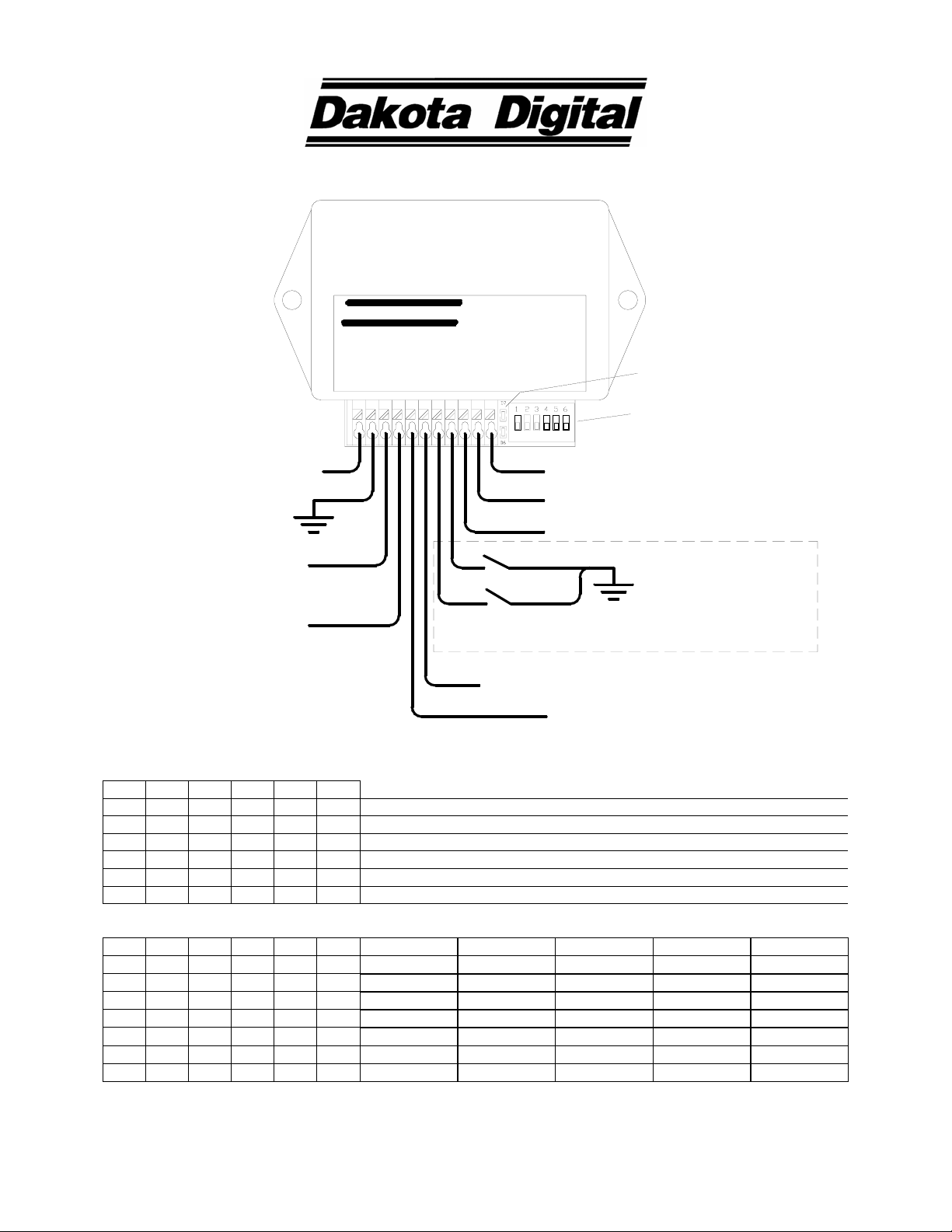
PAC-3500
AUTOMATIC DOOR LOCK CONTROLLER
Dakota Digital
AUTOMATIC DOOR LOCK CONTROL
WARN
UNLCK
LOCK
SPD
GND
PWR
IGN
R PIN
L PIN
PAC-3500
#1 Pin mode sel
#2 Unlock mode
#3 Lock mode
#4-6 Speed select
GEAR
PARK
Indicator LEDs
Option switches
fused constant +12V
ground
1 wire gear signal (optional)
+12V park signal (optional)
fused +12V with key on
Unlock wire on
dual relay pack
Only used for
suicide safety pin
Lock wire on
dual relay pack
see relay wiring diagram
in instructions
Suicide safety pin
switches
Vehicle speed sensor input (optional)
applications.
Safety pin warning output
SWITCH ARRANGEMENT
1 2 3 4 5 6 MODE SELECTED
OFF - - - - - disable suicide safety pin mode
ON - - - - - enable suicide safety pin mode
- OFF - - - - unlock when ignition turned off
- ON - - - - unlock when put in park (1 wire signal1 or 12v park wire must be connected)
- - OFF - - - lock at speed selected by switches 4-6 (Vehicle speed sensor must be connected)
- - ON - - - lock when taken out of park (1 wire signal1 or 12v park wire must be connected)
LOCKING SPEED FOR SENDER TYPE (ppm = pulse per mile)
2000 ppm 4000 ppm 8000 ppm 16000 ppm 128000 ppm
- - - OFF OFF OFF 15
- - - ON OFF OFF 30MPH (48KPH)15MPH (24KPH)7.5MPH (12KPH)
- - - OFF ON OFF 30MPH (48KPH)15MPH (24KPH)7.5MPH (12KPH)
- - - ON ON OFF 30MPH (48KPH)15MPH (24KPH)
- - - OFF OFF ON 30MPH (48KPH)
- - - ON OFF ON 7.5MPH (12KPH)
- - - OFF ON ON 15MPH (24KPH)
- - - ON ON ON 30MPH (48KPH)
1
1 wire gear signal must be from Dakota Digital gear sender (GSS-1000, GSS-2000 etc.)
2
Speed selection switches do not apply when SW 3 is on.
3Speeds are approximate and may vary slightly depending on application
MPH (24KPH)7.5MPH (12KPH)
2,3
Page 2
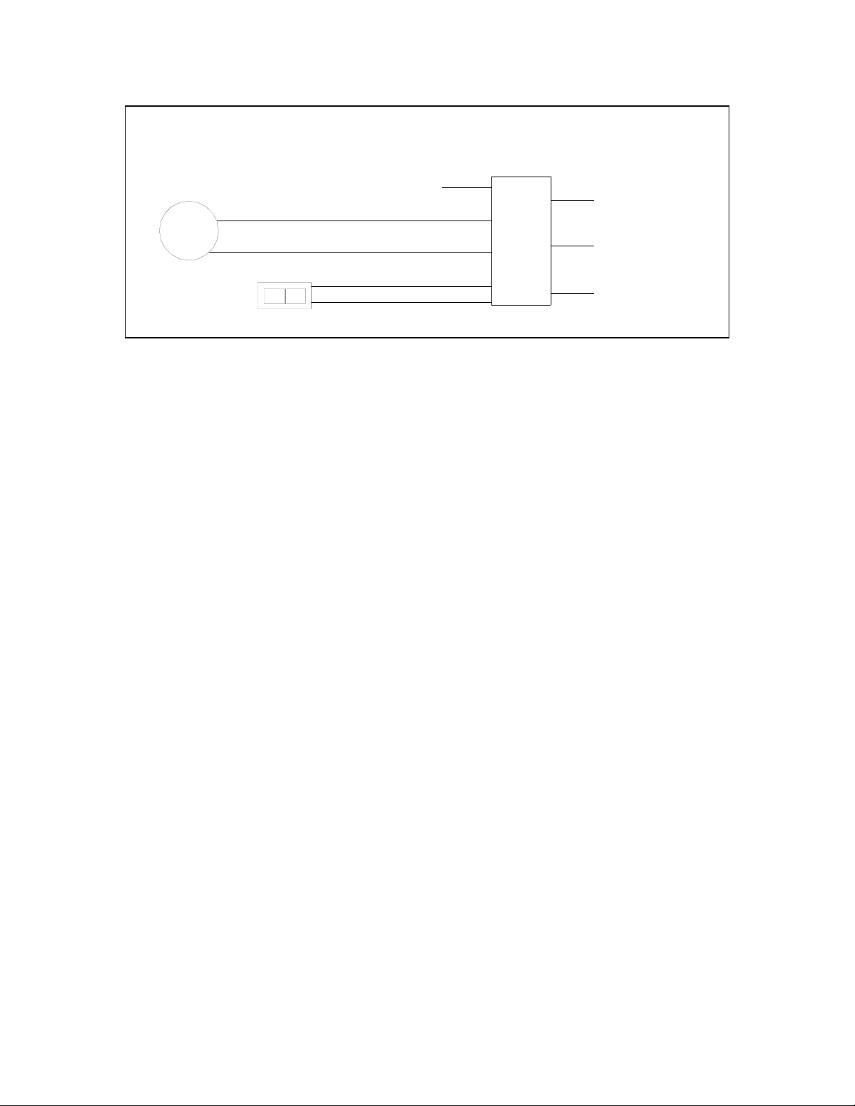
Wiring to a door lock motor. Dakota Digital RLY-2 relay pack shown.
The wires between the switch and the motor will need to be cut, and the relay
pack wired in between as shown.
MOTOR
+12v on lock
Fused 12V power.
PURPLE
BLUE
GREEN
DUAL
RELAY
PACK
BLUE
small wire
RED
To PAC-3500
Lock output.
FUSED 12V POWER
MOTOR
SWITCH
+12v on lock
BROWN
WHITE
GREEN
small wire
To PAC-3500
Unlock output.
Indicator LEDs
The green LED will turn on when the auto-lock module is receiving a signal from the ignition terminal. It will begin
flashing if a vehicle speed signal is present at the SPD terminal.
The red LED will turn on solid if there is a +12v park signal. It will flash if it is receiving a park signal on the 1-wire
Switch 1 Suicide safety pin select switch
Switch 2 Unlock mode select
When switch 2 is off, the doors will only be unlocked when the ignition is turned off.
Switch 3 Lock mode select
When the switch is off, the auto-lock unit will lock when the vehicle exceeds the speed selected by switches 4-6.
Switch 4-6 Speed select
PWR Provide fused constant battery power (+12v) to this terminal.
GND Main ground for auto-lock unit. Poor ground connection may cause the system to not operate properly.
LOCK Negative output used to drive a relay for locking doors. Connect one side of lock relay coil to this terminal and
UNLCK Negative output used to drive relay for unlocking doors. Connect one side of unlock relay coil to this terminal
gear input.
When turned on (switch toward case), this switch selects the Suicide safety pin mode of operation. This mode
enables the warn output and the internal warning tone. It also enables the door pin inputs. After the auto-lock unit
attempts to lock the doors, it checks the suicide safety pin switches (door pin inputs). If one of the pins fails to
lock, the tone and warning output are activated. The tone and warning output will also be activated if the door pins
become unlocked while the vehicle is still in lock condition (over set speed or out of park).
The tone and warning output will remain activated until the pins are manually operated to lock or the auto-lock can
reattempt and succeed to lock the pins.
When switch 2 is turned on, the auto-lock unit will unlock the doors when it receives a park signal from either the
+12v park input or the 1-wire gear input.
When switch 3 is on, the auto-lock unit will lock the doors when there is no park signal on either the +12v park
input or the 1-wire gear input.
These switches are only valid when the auto-lock unit is set to lock on speed signal by turning switch 3 off.
Different speeds may be selected for the most common speed sender types (see chart on first page). The speeds
in the chart are approximate and may vary slightly depending on application. When the speed set by these
switches is reached the auto-lock unit will attempt to lock the doors.
other side to fused constant +12v.
and other side to fused constant +12v.
Page 3

WARN Negative output used to drive bulb for warning output, only used in suicide pin mode. It is capable of switching
0.25A, equivalent to a 3 watt 12V bulb. Connect one wire from bulb to terminal and other wire to fused +12V.
If a larger or high power indicator is used a relay should be used to turn on the light. In this case connect one
side of the relay coil to the WARN terminal and the other side to fused +12v. The relay contacts will then be
used to power the light. Any 12v automotive relay can be used, such as the Dakota Digital, RLY-1 30A relay.
SPD Speed input required only if using lock on speed setting, leave unconnected otherwise.
For 2 wire pulse generators connect one wire to ground and the other wire to SPD terminal. If the signal is
being shared by a cruise control or ECM, make sure they all use a common ground for the pulse generator.
For 3 wire Hall-effect sensors, refer to the installation instructions for the sensor to determine wire color code.
Most 3 wire sensors use the following color code: RED – power, BLACK – ground, WHITE – speed signal.
For speed sensor integrated into a vehicle wiring harness, consult a service manual to determine the col or
code and location of the speedometer signal.
L PIN Required if suicide safety pin mode set (switch 1). If not used leave
& R PIN unconnected. These are inputs from the switches on the suicide safety pin assemblies. The switch will
connect the R PIN or L PIN terminal to ground when the pin is fully actuated. If either of the switches fails to
close when pins are to be locked, the warning tone and output are activated.
IGN Should be connected to have +12v when key is ON. The auto-lock module will not operate unless it receives
the ignition signal.
GEAR Required if set to lock or unlock using park signal and using Dakota Digital gear sender (GSS-1000, GSS-
2000…) in 1-wire gear signal mode. Connect the 1-wire gear signal wire from sending unit to this terminal. If
not used, leave unconnected.
PARK Required if set to lock or unlock on park and a +12V park signal is used. When +12v is applied to the park
terminal, it is read as the vehicle being in park. If not used, leave unconnected.
NOTE: Use either the GEAR terminal or the PARK terminal, but do not use both. The unused terminal should be
left unconnected.
4510 W. 61ST St. N., Sioux Falls, SD 57107
Phone: (605) 332-6513 FAX: (605) 339-4106
www.dakotadigital.com
dakotasupport@dakotadigital.com
©Copyright 2005 Dakota Digital Inc.
Page 4

TROUBLESHOOTING
PROBLEM CAUSE SOLUTION
Module does not respond, no green light
visible.
Module does not lock with speed signal Lock on speed option not selected
Module locks at key on (park lock setting) Poor connection to park input
Module locks at speeds that are too fast
or slow
Module does not unlock Unlock switch setting not as expected.
Warning tone sounds Suicide pin mode selected
Module repeatedly locks and unlocks Module receiving both a park signal and a
Poor connection on IGN terminal.
Poor ground connection
Poor connection to PWR terminal
Speed setting two high
Poor connection on SPD terminal
Poor connection to lock relay
Gear sender unit needs calibration or is not
operating correctly.
Different setting needed on speed switches 4-6 For slower speeds use setting above current setting on
Poor connection on park input (park unlock)
Ignition terminal is constantly powered
Poor connection to unlock relay
Door pins not fully locking
Door pins became unlocked
Broken wire from L PIN or R PIN terminal
Poor ground on safety pin switches
Poor connection on lock relay prevents locking
speed signal (only if set to lock on speed and
unlock on park)
Noise on speed signal line (while in park)
Check for broken or pinched IGN wire.
Check for broken or pinched ground wire.
Check for broken or pinched PWR wire.
Check switch settings (see chart first page)
Select slower speed setting from chart (settings above
current setting on chart)
Check for broken or pinched SPD wire.
Check connections to dual relay pack.
Red light stays off when placed in park, check that
GEAR terminal is connected to 1-wire gear signal OR
that PARK terminal is connected to 12v park signal.
Check for broken wires.
If red light stays off when placed in park and all
connections are ok, see instructions for gear sender.
chart. For faster speeds use settings below current
setting on chart.
Check switch 2 setting to chart
If red led doesn’t light or blink when placed in park,
check connection to park terminal being used.
If green light doesn’t go out when ignition turned off,
relocate feed to ignition terminal to 12v only with key on.
Check connections to dual relay pack.
If not in suicide pin mode turn switch 1 off
Check that door pins for binding or obstructions.
Ensure that pins stay locked during normal operation
Check for broken wire from pin assembly switch to unit
check / relocate ground on pin assembly switches
Check connections on dual relay pack
Correct wiring so that no park signal is present when
there is a speed signal.
Reroute speed signal wire away from spark plug wires or
other noisy wires.
SERVICE AND REPAIR
DAKOTA DIGITAL offers complete service and repair of its product line. In addition, technical consultation is available to
help you work through any questions or problems you may be having installing one of our units.
Should you ever need to send the unit back for repairs, please package the product in a good quality box along with plenty
of packing material. Ship the product by UPS or insured Parcel Post. Be sure to include a complete description of the
problem, your full name and address (street address preferred), and a telephone number where you can be reached
during the day. An authorization number for products being returned for repair is not needed. Any returns for warranty
work must include a copy of the dated invoice or bill of sale.
PAC-3500 LIMITED WARRANTY
proven defective in material or workmanship within 24 MONTHS FROM THE DATE OF PURCHASE, such defect(s) will be repaired or replaced (at the
Company’s option) without charge for parts or labor directly related to repairs of the defect(s).
of sale), name, address, phone number, and specification of defects, transportation prepaid, to the factory. This Warranty is valid for the original
purchaser only and may not be transferred.
which in the opinion of the Company has been damaged through alteration, improper installation, mishandling, misuse, neglect, or accident.
OF MERCHANTABLITY, SHALL BE LIMITED TO THE DURATION OF THIS WRITTEN WARRANTY. ANY ACTION FOR BREACH OF ANY
WARRANTY HEREUNDER INCLUDING ANY IMPLIED WARRANTY OF MERCHANTABLITY MUST BE BROUGHT WITHIN A PERIOD OF 24
MONTHS FROM DATE OF ORIGINAL PURCHASE. IN NO CASE SHALL THE COMPANY BE LIABLE FOR ANY CONSEQUENTIAL OR
INCIDENTAL DAMAGES FOR BREACH OF THIS OR ANY OTHER WARRANTY, EXPRESSED OR IMPLIED, WHATSOEVER. No person or
representative is authorized to assume for the Company any liability other that expressed herein in connection with the sale of this product.
UNDER THIS WARRANTY IS LIMITED TO THE REPAIR OR REPLACEMENT PROVIDED ABOVE AND, IN NO EVENT, SHALL THE COMPANY’S
LIABILITY EXCEED THE PURCHASE PRICE PAID TO THE PURCHASER FOR THE PRODUCT.
so the above limitations or exclusions may not apply to you. This warranty gives you specific legal rights and you may also have other rights which vary
from state to state.
DAKOTA DIGITAL (the Company) warrants to the ORIGINAL PURCHASER of this product that should it, under normal use and condition, be
To obtain repair or replacement within the terms of this Warranty, the product is to be delivered with proof of warranty coverage (e.g. dated bill
This warranty does not cover nor extend to damage to vehicle electrical system. This Warranty does not apply to any product or part thereof
This Warranty is in lieu of all other express warranties or liabilities. ANY IMPLIED WARRANTIES, INCLUDING ANY IMPLIED WARRANTY
The Company does not warrant that this product cannot be compromised or circumvented. THE EXTENT OF THE COMPANY’S LIABILITY
Some states do not allow limitations on how long an implied warranty lasts or the exclusion or limitation if incidental or consequential damage
 Loading...