

Dakota Digital PAC-2750 Installation Manual
IMPORTANT NOTE:
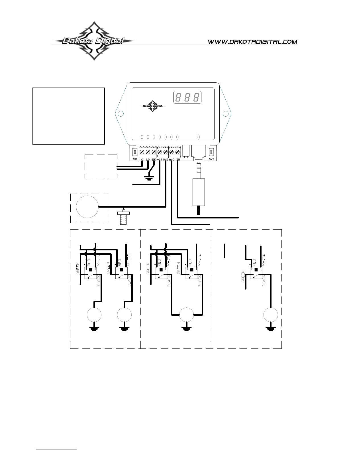
The +12V for the
off.
controller should NOT
be taken from the same
circuit as the Fan Power
12V as this can cause
the fan to cycle on and
Choose
option
below
PAC-2750
ELECTRIC COOLING FAN CONTOLLER
www.dakotadigital.com
techsupport@dakotadigital.com
605-332-6513
+12 BAT
GROUND
FAN HIGH
FAN LOW
SW1
PAC-2750
FAN CONTROLLER
A/C
SENDER
IGNITION
BIM I/O
ADJUST
CUSTOM
SW2
GAUGE
(not used in
sender only
or BIM
application)
Fused battery 12V
GAUGE
+12V
FAN2
Fan PWR +12V
Fan
High
-
+
-
SENDER
(not used in BIM
application)
Fan
Low
-
+
FAN1
-
+12V
Fan
High
-
HIGH
Fan PWR +12V
two separate fans dual speed fan
To gauge control box
or another BIM
+12V with key ON
A/C clutch cycle switch (+12V trigger)
Fan
Low
-
Fan
High
NOT
CONNECTED
+12V
Fan
Low
-
Fan
PWR
+
FAN
+
LOW
-
+12V
+
FAN
-
single fan
Required components for installation:
The PAC-2750 is shipped with necessary components for use with a single fan on a gauged system. These parts include:
1 PAC-2750 module
1 RLY-3 relay with wiring harness
1 BIM data cable
1 Instruction manual
For some options of the PAC-2750, additional components are required. These are listed below.
- Second RLY-3 assembly (needed for dual fan or two speed fan operation)
- 300ºF sender Dakota Digital temp sender (for operation without a gauge)
MAN# 650411:B

Operation
The electric cooling fan controller provides a way to run up to two electric engine cooling fans or one two speed cooling
fan. (A second relay, sold separately, is required for two speed or dual fan operation). The controller monitors the engine
temperature using a dedicated sender, a gauge and its sender, or directly from a Dakota Digital BIM connection. When
the engine temperature goes above a user adjustable set point, the fan is turned on with a relay. When the engine has
cooled below a user selectable off temperature, the fan is shut off. Separate on and off temperatures can be set for the
high and low fan outputs. The controller will also run the fan when the air conditioner requires, by detecting when the air
conditioning clutch is engaged. When the temperature information is provided by a Dakota Digital BIM connection, a high
speed shut-off is also available to disable the fans from turning on once the vehicle is above a user adjustable speed.
The unit can be set to keep the fan running (if the engine is hot enough) after the key is turned off. Several delay times are
available from no delay to five minutes. The display will countdown the seconds left before the fan is turned off. If the
battery voltage drops too low, the fan will be turned off and a “Lo bAt” message will display for the remainder of the time.
Settings for several gauge systems are included to make installation with a gauge easier. The included gauges are
Stewart Warner, Classic Instruments, VDO, and Autometer. If the gauge being used isn’t included, a custom calibration
option allows the system to be calibrated to any gauge with clear numerical temp markings. This is accomplished by
setting the controller to match the marks on the gauge with a few steps described in detail in the installation instructions.
The engine temperature can also be read directly from an OBDII diagnostic port with the use of a Dakota Digital BIM-01-1
unit.
WARNING!!!: The fan will turn on and run continuously if the sender is disconnected as a failsafe. Always keep clear of
the fan unless the battery is disconnected. When entering setup mode with a VHX or VFD gauge system and the PAC-2750
connected with a BIM cable the fan will begin running continuously after a 2 minute delay.
IMPORTANT NOTE!!!: If using a gauge with this unit, always ensure that your gauge is working properly. If the gauge is not reading
correctly, the fan control unit will not have correct temperature information and cannot be guaranteed to properly control the fan,
possibly leading to overheating and engine damage.
If the gauge uses a two-wire temperature sender (such as Autometer full sweep) use of a dedicated Dakota Digital sender is
required.
If a gauge is not used, ONLY a Dakota Digital 300ºF sender should be used (Dakota Digital part SEN-04-1, SEN-04-2, SEN04-4, SEN-04-5, SEN-04-6, SEN-04-7, or SEN-04-8). Other senders may not give a correct reading to the control unit.
Custom gauge calibration requires numerical marks, stock “C-NORMAL-H” type gauges cannot be accurately calibrated to.
Installation
Note: Mount ONLY in vehicle cabin. Controller is not designed for engine compartment mounting.
The terminal strip on this unit has 7 connections:
1. Fan high relay Connect to the white wire on the high fan relay assembly
(for single fan applications leave unconnected)
2. Fan low relay Connect to the white wire on the low fan relay assembly
3. Ground Connect to a good chassis ground
4. Power Connect to a fused 12V battery
5. Sender Connect to the engine temperature sender wire.
6. A/C clutch Connect to the cycle switch on systems with air conditioning (+12v)
(on systems without air conditioning leave unconnected)
7. Ignition Connect to a circuit which has +12V only with the ignition key ON. (switched power)
Relay wiring:
White Connect to control unit
Green Connect to fused 12V battery circuit that can run cooling fan
Red Connect to fused 12V battery
Black Connect to cooling fan
Factory Presets
This controller comes preset to use a dedicated sender as follows:
Dakota Digital Sender only (no gauge, see note above for 300ºF sender options)
One single speed fan
205ºF on temperature
200ºF off temperature
30 sec Fan off delay
If the factory settings don’t fit your application, you will need to go through the setup procedure on the following page. At
anytime during the setup procedure, the key may be turned off and the settings up to that point will be saved.
MAN# 650411:B

Set Up
1. Press and hold SW2, then turn the key on.
2. Release SW2, then press and release SW1 to move onto the next step.
3. To select temperature scale to use, press and hold SW1 to select F (Fahrenheit)
or press and hold SW2 for C (Celsius). Hold the switch for longer than one second to select. Once a temperature
scale is selected, the display will flash and go on to next setting.
4. Display will now read Lon indicating low fan on temperature is to be set. Use SW1 or SW2 to select the
temperature at which the fan should turn on. Press both switches to save the setting. Display will flash when
setting is saved.
Note: SW1 increases the temperature, while SW2 decreases the temperature.
5. Display will now read OFF indicating low fan off temperature is to be set. Again, use SW1 or SW2 to set the
temperature at which the fan should turn off. Press both switches to save the setting.
6. If two fan or dual speed fan mode was previously selected, temperature settings for the high fan output are at this
point in setup for convenience. If single fan mode is set up, setup will skip high temp settings and go to Step 7.
6a. Display will now read Hon indicating high fan on temperature is to be set. Use SW1 or SW2 to set the
temperature at which the fan should turn on. Press both switches to save the setting.
6b. Display will now read OFF indicating high fan off temperature is to be set. Use SW1 or SW2 to set the
temperature and press both switches to save the setting.
7. Display will read dLy Use SW1 or SW2 to cycle through the following options. Press both switches to select an
option.
Display Option
OFF
Fan will turn off when key is turned off.
0.5 If fan was running at key off, it will continue to run for 30 seconds after key is turned off.
0.7 If fan was running at key off, it will continue to run for 45 seconds after key is turned off.
1.0 If fan was running at key off, it will continue to run for 1 minute after key is turned off.
2.0 If fan was running at key off, it will continue to run for 2 minutes after key is turned off.
3.0 If fan was running at key off, it will continue to run for 3 minutes after key is turned off.
5.0 If fan was running at key off, it will continue to run for 5 minutes after key is turned off.
8. Display will read FAN indicating fan type is to be set. Use SW1 or SW2 to select the fan type used. Press both
switches to save setting.
Display Option
1 one single speed fan (only low fan output used)
2 two single speed fans (high and low fan outputs both on for high temp,
& some dual spd fans only low fan output on for low temp)
SPD one dual speed fan (high fan output on, low fan off for high temp,
high fan off, low fan on for low temp)
Note: If two fan or dual speed are selected and high fan temp setting was not set before, setup will return to Step
6 to allow temp settings to be made.
9. Display will read VAr for a future option. This should be left OFF. Press both switches to save setting.
MAN# 650411:B
 Loading...