

Page 1
1968-77 Chevy Corvette
Dakota Digital Gauge Installation
This sheet covers the installation of the Dakota Digital gauge kit into the original clusters.
1. Remove the clusters from the vehic le. The procedure for the speedometer
and tachometer clusters are the same, but only one side is shown in the
photos.
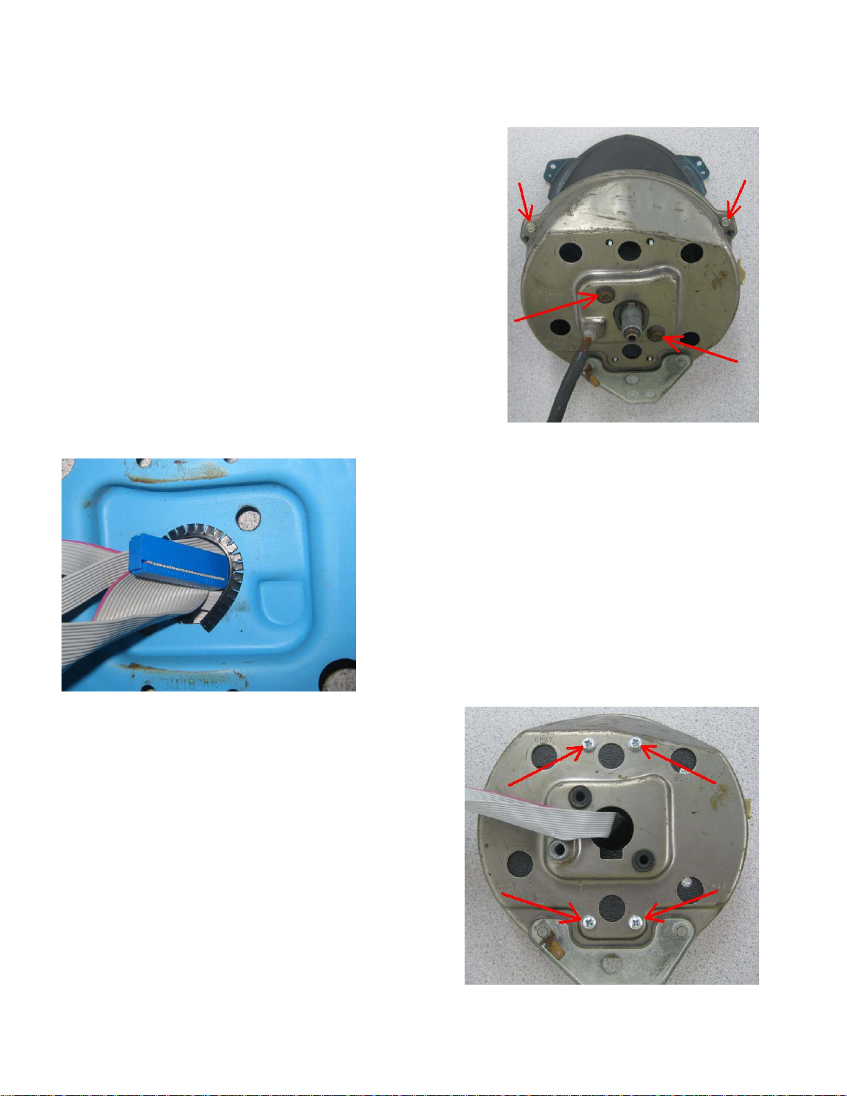
2. Remove the three screws holding the bezel on to the gauge can. Two are
indicated by the upper arrows in the photo at right; one is on the bottom side
of the can and cannot be seen here. After the bezel is set aside, remove the
two screws near the center of the can to remove the original gauge. On the
speedometer can (shown) you will also need to remove the trip meter reset
cable.
3. Use the provided flexible grommet mater ia l on the edge of the
mechanical cable openings on the original gau ge cans to protect the
ribbon cables. A few dabs of silicone will help hold it in place. Pass the
ribbon cables through the lined cable openi ngs until the gauge
assemblies sit into the cans and the cables are not being pinched.
4. Use four of the supplied #10-32 x .500” screws and lock washers
to secure the gauge assembly into the can. It is recommende d to start
all the screws before tightening completely. If the screw holes do not
line up properly, the gauge a s sembly is in the wrong can.
5. Re-install the bezels to the gauge cans using the screws removed in
step 2.
MAN#650277
Page 2
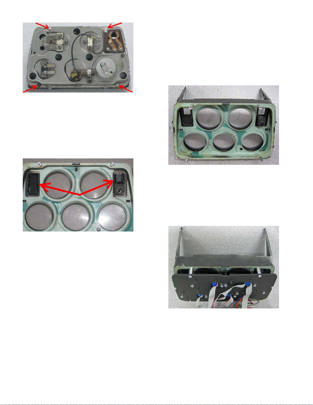
6. Remove the center gauge cluster from the vehicle. From the back
side, remove the four screws as indicated by the arrows in the photo at
left which hold the stock gauges to the bezel. The stock gauge
assembly can be set aside.
7. Leave the clear lens and gauge separator plate in the bezel and
install the four provided #6-32 x .625” standoffs in the holes that
you removed the screws from in the pr evious step. Take care not to
over tighten as the threaded portion standoffs can break.
8. Included are some lenses that can be used as block offs for the
openings at the sides of the top two gauges as indicated by the arrows
in the photo at left. Due to factory changes over the years, three
different sizes are provided. The small one is not square and will only
fit in one direction. Set these in place and secure with silicone.
9. Set the Dakota Digital gauge cluster onto the standoffs and use
the four #6-32 x .250” screws and lock washers to secure it to the
bezel. It is recommended to start all four screws before tightening
any completely.
When installing the cluster back into the vehicle connect the two
gray ribbon cables to those coming off the main cluster. The clock
will need to be wired separately. Two remote mount time set
switches are wired to the clock and will require 1/4” holes to be
drilled to mount them.
See the main instruction manua l for the remainder of the installation.
The Odyssey clock from Dakota Digital, Inc. incorporates the reliability and quality
of our standard gauges, along with several unique features and easy mounting. These
features include:
• Quartz accuracy.
• Night dimming feature.
• Very low standby power to prevent battery drain.
• High Visibility VFD display for sunlight readability.
MAN#650277
Page 3

The Odyssey series clock displays the current time in 12 hour format. The high
brightness display matches our other Odyssey, STR, and VFD3 series gauges and has
the same night brightness dimming capability.
Operation:
The gauge needs the red, orange, and black wires connected to operate. The red
wire should have switched 12 volt power from an ACC. point on the fuse panel. The
orange wire should have constant 12 volt power. The black wire should be connected to
a good ground point. When the blue wire has 12 volts, it will dim the display for night
viewing.
Setting the time:
The remote mounted red and black push buttons will be used to set the clock. The
BLACK “set” button advances hours, the RED “set” button advances minutes. Each time
that you make a change to either the hours or minutes, the seconds are reset to zero.
Adjusting the accuracy:
The clock is accurate to +/-2 minutes a month as it is sent. It can be tuned for
better accuracy if desired. Press and hold both of the set buttons for several seconds.
The clock will display “C 0”. The “C” indicates that it is in the calibration mode and the
second number is the current calibration value. The calibration value indicates the
number of seconds to add or subtract each d ay. The clock can be adjusted from +7
sec/day to -7 sec/day.
Press the minute set button to change the cal value. Press the hour set button to
return to normal clock operation.
Wiring:
BLACK - connect to a good ground point in the vehicle.
RED - connect to switched 12 volt power point.
(An accessory terminal will work for this.)
ORANGE - connect to a constant 12 volt power point.
(This will keep the correct time.)
BLUE - connect to the tail light circuit.
Troubleshooting guide.
Problem Possible cause Solution
Clock will not light up Red wire does not have Connect to a location that has power
power. when the key is on.
Orange wire does not have Connect to a location that has power
power. all of the time.
Black wire is not getting Connect ground to a different location.
a good ground.
Power is reversed. Connect black to negative ground, red and
orange to +12V power.
Clock is damaged. Return clock for repair. (see instructions)
Clock will not turn off when The red and orange wires Connect the red to switched power, the
the key is off. are reversed. orange to constant power.
Clock lights up, but does Loose connection on orange Reconnect orange wire.
not read correctly. po wer wire.
MAN#650277
Page 4

Poor ground connection. Move ground to different location
Time is not set. Set time. (see instructions)
Clock is damaged. Return clock for repair. (see instructions)
Clock will not keep time. Orange wire does not have Connect to a location that has power
when
constant power. the key is on or off.
Loose connection on orange Reconnect orange wire.
power wire.
Poor ground connection. Move ground to different location
Clock will not dim . Blue wire is not connected Check wiring connections.
correctly.
Clock remains dim at all Blu e wire is getting power Connect blue wire to location that only
times. all of the time. has power when the headlights are on.
Battery is very low. Recharge or replace vehicle battery.
Clock is damaged. Return clock for repair. (contact factory)
Technical specifications
Minimum operating voltage - 7 volts
Maximum operating voltage - 18 volts
(operating at or near maximum rating for an extended time can damage unit)
Clock accuracy - ±2 minute per month
Typical current draw (@ 13.8V) - 0.13 A
Standby current draw (key off) - 0.002 A
SERVICE AND REPAIR
through any questions or pr oblems you may be having installing one of our products. Please read through the Troubleshooting Guide. There, you will find
the solution to most problems.
Should you ever need to send the unit back for repairs, please call our technical support line, (605) 332-6513, to request a Return Merchandise
Authorizati o n number. Packag e the pro duc t in a goo d quality box along with plenty of pack ing mat e rial. Ship the product by UPS or insured Parcel
Post. Be sure to include the RMA number on the package, and include a complete description of the problem with RMA number, your full name and
address (street address preferred), and a telephone number where you can be reached during the day. Any returns for warranty work must include a copy
of the dated sales receipt from your place of purchase. Send no money. We will bill you after repair.
DAKOTA DIGITAL offers complete service and repair of its product line. In addition, tec h nical con sul t ati o n is avail able to help you work
Dakota Digital 24 Month Warranty
defective in material or workmanship within 24 MONTHS FROM THE DATE OF PURCHASE, such defect(s ) will be re pai r ed or re placed at Dakota
Digital’s option.
Warranty does not apply to an y prod uct or part t he reo f whi ch in th e opini on of t he Com pa ny has been damaged throu gh al te rati on, improper installation,
mishandling, misuse, neglect, or accident.
merchantability, shall be limited to the duration of this written warranty. Any action for breach of any warranty hereunder, including any implied warranty
of merchantability, must be brought within a period of 24 months from date of original purchase. No person or representative is authorized to assume, for
Dakota Digital, any liability other than expressed herein in connection with the sale of this product.
DAKOTA DIGITAL warrants to the ORIGINAL PURCHASER of this product that should it, under normal use and condition, be proven
This warranty does not cover nor extend to damage to the vehicle’s systems, and does not cover removal or reinstallation of the product. This
This Warranty is in lieu of all other expressed warranties or liabilities. Any implied warranties, including any implied warranty of
4510 W. 61ST St. N., Sioux Falls, SD 57107
Phone: (605) 332-6513 FAX: (605) 339-4106
www.dakotadigital.com
dakotasupport@dakotadigital.com
©Copyright 2006 Dakota Digital Inc.
MAN#650277
 Loading...