

Page 1
INSTALLATION AND OPERATOR’S MANUAL
harness
(x1)
Digital Climate Control for Vintage Air GEN-IV systems
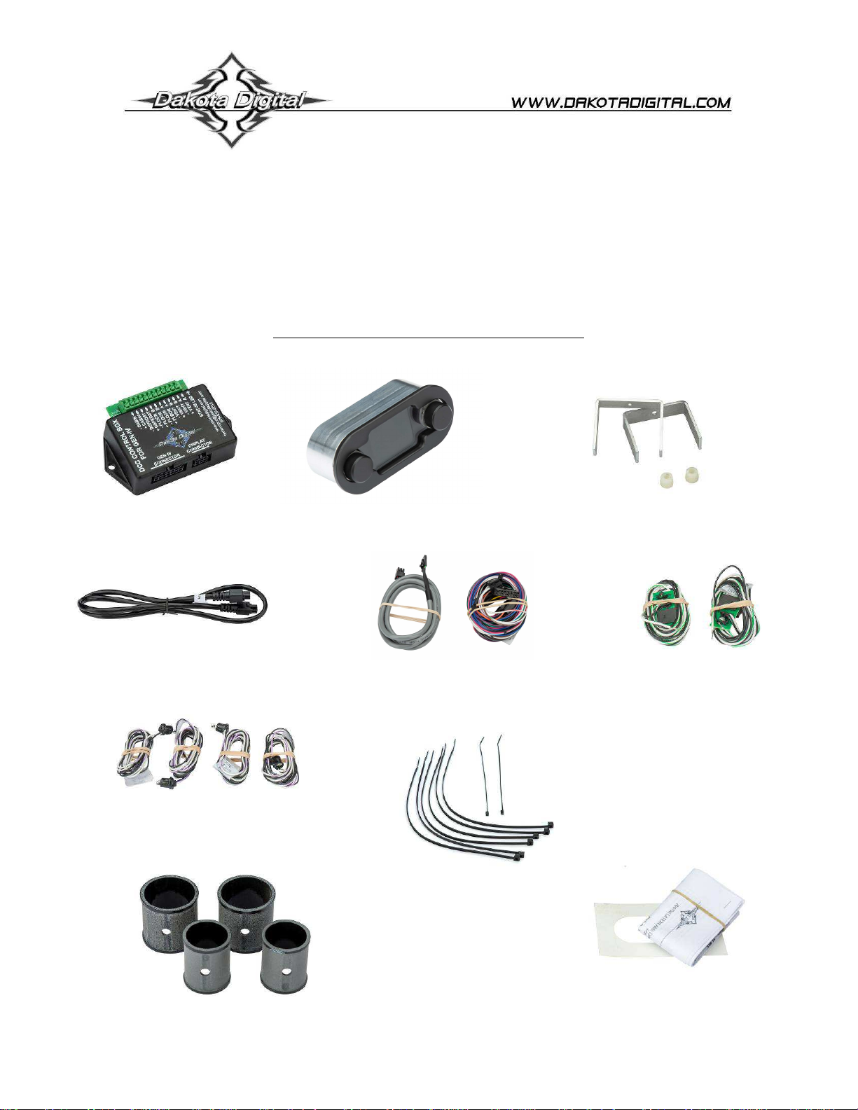
PARTS INCLUDED WITH THIS SYSTEM
DCC control box (x1)
HLC harness (x1)
Grommet temp sensors (x4)
2 ½” Vent sensor housings (x2)
FOR
DCC-4000
DCC-4000 display (x1)
DCC display
11” plastic ties (x6)
2” Vent sensor
housings (x2)
Mount brackets (x2)
DCC controller
harness (x1)
6 “ plastic ties (x2)
Cutout template (x1)
Thumb nuts (x2)
Clip temp sensors (x2)
Installation / operator’s
manual (x1)
1 MAN # 650702
Page 2
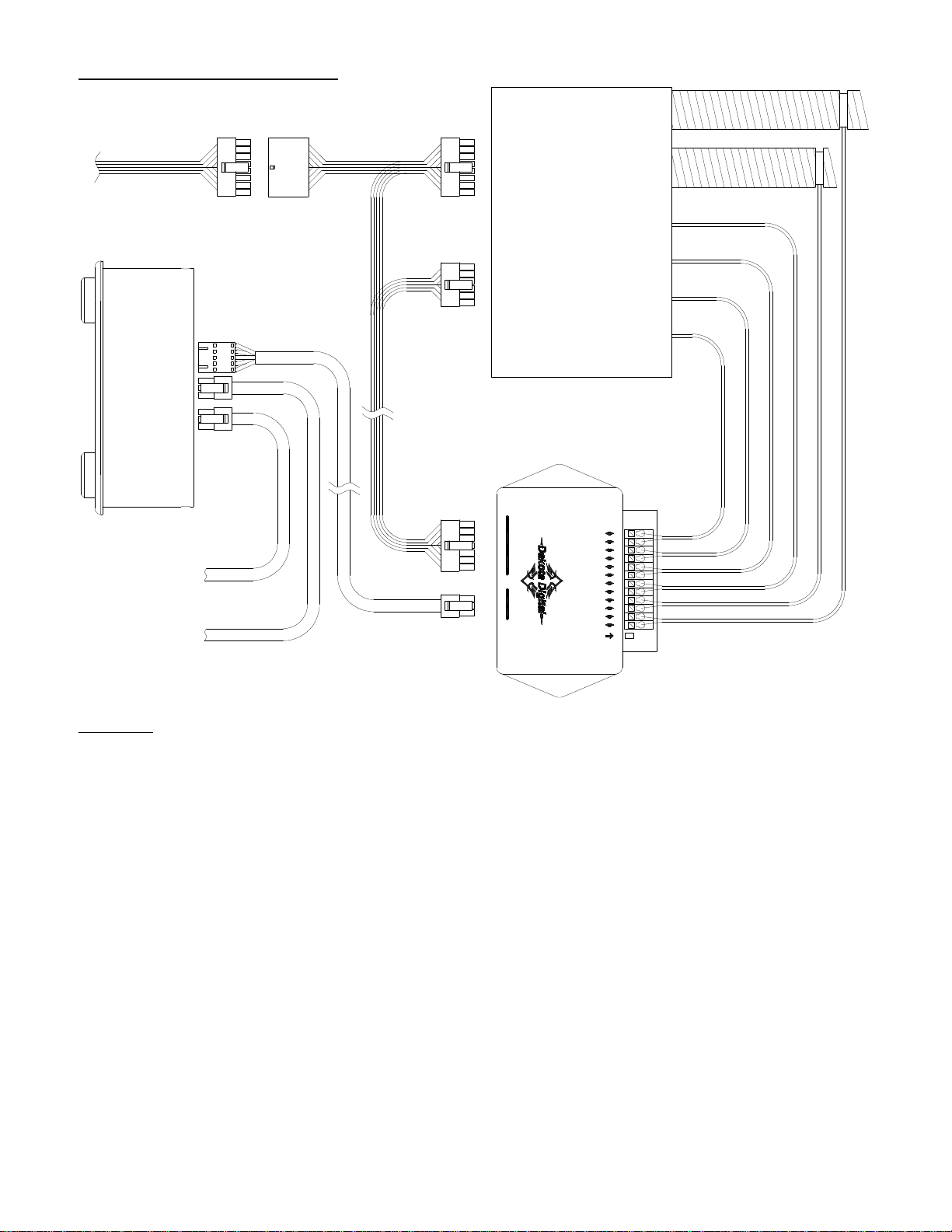
CONNECTION DIAGRAM:
Vent hoses
GEN IV
MODULE
GEN IV wiring
harness
DCC controller
harness
Temperature
sensor
connections
DCC CONTROL BOX
FOR GEN-IV
CONNECTOR
DCC-4000 display
To HDX/RTX Control
CLOCK CABLE
(optional*)
To HLC/RLC clock
DCC display
harness
GEN-IV
CONNECTOR
DISPLAY
www.dakotadigital.com
techsupport@dakotadigital.com
STATUS LED
605-332-6513
- CABIN
+ CABIN
- DEFROST
+ DEFROST
- FLOOR B
+ FLOOR B
- FLOOR A
+ FLOOR A
- VENT B
+ VENT B
- VENT A
+ VENT A
connection (optional*)
WIRING:
Connect temperature sensor wires to control box. (For more details see STEP 7: WIRE TEMP SENSORS)
Plug the 5 pin connector of the Display Harness into the display. Route the other end of the cable to the
*Optional connections for HDX/RTX theme matching. See NIGHT TIME DIMMING AND THEMES on page 7.
DCC-control box and plug it into the control box connector labeled “DISPLAY CONNECTOR.”
Connect the 14 pin connector of the DCC controller harness to the connector labeled “GEN-IV
CONNECTOR”.
Route the DCC controller harness to the GEN-IV module.
Connect the 12 pin wire connector to the 12 pin connector on the GEN-IV module.
Connect the 16 pin wire connector to the 16 pin main wiring harness connector on the GEN-IV.
Connect the GEN-IV harness into the remaining 16 pin connector on the DCC controller harness.
(optional*) Using the HLC harness (2 six pin connectors) connect to either one of the 6 pin connectors on
the DCC-4000 display. Connect the other end to the “CLOCK CABLE” port on HDX or RTX control box.
(optional*) If the HDX / RTX system has an analog clock, connect its HLC harness to the remaining 6 pin
connector on the back of the DCC-4000 display.
If not already wired, wire the GEN-IV wiring harness as described in the GEN-IV manual.
2 MAN # 650702
Page 3
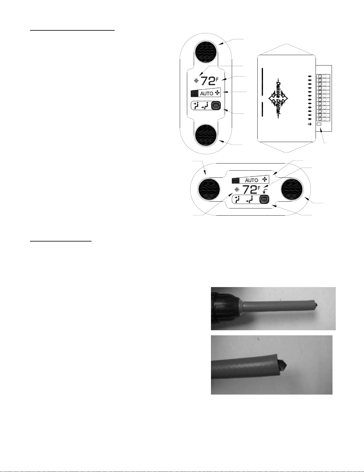
FEATURE DIAGRAM:
1. Temperature knob
1
Turn to adjust temperature
Press to toggle between AC and Econ
2. AC / ECON indicator
Shows snowflake for AC, and a
snowflake in backslash-circle for Econ
3. Temperature display
Shows the set temperature
4. Fan speed display
Shows fan speed
5. Blower mode display
Shows location of air output
6
DCC CONTROL BOX
2
CONNECTOR
3
4
GEN-IV
CONNECTOR
DISPLAY
5
techsupport@dakotadigital.com
FOR GEN-IV
- CABIN
+ CABIN
- DEFROST
+ DEFROST
- FLOOR B
+ FLOOR B
- FLOOR A
+ FLOOR A
- VENT B
+ VENT B
- VENT A
+ VENT A
STATUS LED
www.dakotadigital.com
605-332-6513
6. Blower knob
Turn to adjust fan speed and blower
mode, push to select adjustment
1
4
3
mode
7. Status light
Indicates current status of DCC
control unit
2
5
INSTALLATION:
NOTE: While installation is possible with the GEN-IV system already in the vehicle, it is easier to install some of
the sensors when you have full access to all sides of the GEN-IV module. If the GEN-IV is not yet installed in your
vehicle, we recommend installing the temperature sensors first.
STEP 1: INSTALLING THE DEFROST SENSOR
The supplied grommet type temperature sensors require a
3/8” hole to be drilled so they can be inserted into the
housing. To prevent drilling too deeply, create a stop for
your drill bit (see photos at right) with a piece of rubber
hose or small block of wood that is long enough to allow
just the tip (about ¼”) of the bit to protrude.
NOTE: As an alternative to drilling, one of the extra Vent
Sensor Housings could be used to put the sensor in one of
the defrost duct tubes. This should only be done if drilling
the hole is difficult or impossible with an installed GEN-IV
system. See STEP 5 for install method.
3 MAN # 650702
7
6
Page 4

Using the 3/8” drill bit with the proper rubber
or wood stop installed, drill a hole in the
defrost duct in the location shown.
Insert one of the four supplied grommet type
temperature sensors into the drilled hole with
the wires pointing to the outside of the duct
housing. The sensor should snap into the
hole with the collar of the sensor resting
against the housing.
STEP 2: INSTALLING THE FLOOR SENSORS
Push a clip type temperature sensor onto
the side wall of each opening of the floor
duct so that the sensor sits inside the
duct at about the center of the opening.
It is recommended to label the free end of
the sensor wires to ensure proper
connection to the control box later.
STEP 3: INSTALLING THE CABIN SENSOR
Secure one of the grommet type
temperature sensors to the grate of the
blower fan using the supplied 6” plastic
ties. The sensor should be mounted so
that the silver colored element will be in
the incoming airflow to the fan when the
fan is running.
Be careful that the plastic tie, the sensor,
or its wires will not contact the fan blades
when the fan is running.
Label the wires for the Cabin Sensor for
easier identification later.
Defrost
sensor
location
Floor
sensor
locations
4 MAN # 650702
Page 5

STEP 4: INSTALL THE GEN-IV MODULE
Install the GEN-IV module if it has not yet been installed in the vehicle. Refer to the installation manual for
the GEN-IV module for detailed instructions for your application.
STEP 5: INSTALL THE VENT SENSORS
The vent temperature sensors are
mounted in the flexible duct tubing from
the GEN-IV module. Determine which
two tubes will have the sensor and cut
the tubing a minimum of 6” away from
the GEN-IV module. Choose tubes to
vents that will blow the most air or blow
most directly on passengers in the
vehicle.
Of the four included Vent Sensor
Housings, use the two that fit the
diameter of the cut flexible tubing. Insert
the two remaining grommet type
temperature sensors into the predrilled
holes in these Housings.
Work the Vent Tubes over both ends of
the Sensor Housing and secure the tube
on both sides of the housing using the provided 11” plastic ties. Make sure the plastic ties are positioned
over the body of the Sensor Housing so the raised end of the Housing holds the Tube from slipping off.
STEP 6: MOUNT THE CONTROL BOX
Find a location to mount the DCC control box where the wires will reach without being pulled. There are
two tabs on the case of the control box to allow for easier mounting.
STEP 7: WIRE THE TEMPERATURE SENSORS
Wire the temperature sensors’ wires to the connection strip on the DCC control box. The small tab on the
top of the connector can be pressed down with a screw driver to allow insertion of the stripped ends of the
sensor wires. Connect the black wire to the “-” terminal. The other wire is connected to the “+” terminal.
Take care when connecting the sensors to the control box. If the sensors are connected to the wrong
terminals, the controller will not control the temperature properly. Either Floor Sensor can be connected to
either of FLOOR terminal (A & B). Similarly, either Vent Sensor may be connected to either VENT terminal.
STEP 8: MOUNT THE DISPLAY
Determine your mounting location of the display and use the
provided cutout template to make the opening for the display.
Insert the display into the opening from the front of the dash.
Place a mounting bracket onto each of the studs so that the two
legs of the bracket contact the dash panel along the sides of the
display unit.
Place a thumb nut onto each of the studs to hold the bracket in
place. Tighten the thumb nut to push the bracket up against the
back of the dash panel to secure the display in place.
STEP 9: WIRING
(Refer to the wiring diagram and steps on page 2.)
thumbnut (x2)
Mounting clip (x2)
dashboard
5 MAN # 650702
Page 6

OPERATION:
BLOWER KNOB (knob on right side for horizontal, or bottom side for vertical):
The blower knob handles two adjustments which can be selected by pressing the knob. Each press and
release of the knob will toggle adjustment modes on the display as indicated below. For horizontal display
modes, an arrow indicator points to the selected adjustment. For vertical displays the selected adjustment
is on the bottom, closest to the knob.
Knob adjusts mode knob adjusts fan speed knob adjusts mode knob adjusts fan speed
MODE ADJUSTMENT:
In mode adjustment, turning the knob clockwise will move the slider toward the defrost mode. Turning the
knob counter clockwise will move the slider toward the vent mode. If the slider is in the middle, floor mode
is selected. Any blended mode along the scale may be chosen.
Mode adjustments are handled automatically when in auto mode. The word “AUTO” is displayed between
the vent and floor icons in the blower mode display area, to indicate when the system is in auto mode.
Turning the knob past either end of the scale will set mode adjustment to auto mode.
FAN ADJUSTMENT:
In fan adjustment, turning the knob will change the fan speed. A clockwise turn will increase fan speed. A
counter clockwise turn will decrease it. Turning the fan speed all the way down will turn the system off.
If the fan speed is under automatic control, “AUTO” will appear in the fan speed display area. Making
adjustments to the fan speed will take the fan out of auto mode and the “AUTO” will no longer be displayed.
Automatic fan speed can be turned back on by turning the knob past the maximum setting. The fan will also
return to auto mode whenever an adjustment is made to the temperature setting.
TEMPERATURE KNOB (knob on left side for horizontal, or top side for vertical):
The temperature knob handles changes to the set temperature and AC mode.
TEMPERATURE ADJUSTMENT:
Turning the knob will change the temperature setting. A counter clockwise turn will decrease the
temperature setting. A clockwise turn will increase the temperature setting.
A setting of 60F (16C) will put the system in full cool mode. The controller will cause the GEN-IV module to
be driven in maximum A/C regardless of the temperature readings from the sensors.
A setting of 90F (32C) will put the system in full heat mode. The controller will cause the GEN-IV module to
be driven to maximum heat regardless of the temperatures reading from the sensors.
For all other temperature settings, the controller will always work toward maintaining the air in the cabin at
that set temperature. If the fan or mode is set to auto, the fan speed or airflow direction will also be
adjusted in order to best achieve this set cabin temperature.
AC / ECON SETTING:
Pressing the knob toggles the AC mode between AC and Econ (snowflake symbol on or crossed out).
HORIZONTAL DISPLAY MODES
push
knob
VERTICAL DISPLAY MODES
push
knob
6 MAN # 650702
Page 7

AUTOMATIC FAN:
The fan speed is automatically controlled by the DCC control unit in order to best achieve the set cabin
temperature. However, the fan speed can be temporarily set to a faster or slower speed using the blower
knob in fan adjustment mode. The fan will stay at this set speed until an adjustment is made to the set
temperature. After an adjustment to the set temperature, the fan speed will return to automatic control.
AUTOMATIC MODE SELECTION:
When the system is turned on, the mode (direction of airflow between floor, vent and defrost) is
automatically selected by the controller to best achieve the set cabin temperature. For heating, the airflow
will be set to the floor and some defrost. For cooling, airflow will be set to the vents.
The location of airflow can be set manually by using the blower knob in mode adjustment mode. Once a
change is made to the airflow location, that setting will remain in manual mode until the key is turned off
and back on. Alternatively, automatic airflow can be turned back on by turning the knob past the ends of
the selection bar until “AUTO” appears between the vent and floor icons.
TURNING SYSTEM OFF / ON:
The system can be turned off by turning the fan speed down past the lowest speed. The display will change
to read “OFF” and the fan will be turned off. The AC will not run when the system is off.
Turning the fan speed back up will turn the system back on.
AC / ECON:
Pressing the temperature knob during normal operation will toggle the AC / econ mode. If the system is
currently in AC mode, it will turn the AC off. If it is currently in econ mode, it will turn the AC on. AC mode is
indicated by a snow flake next to the temperature reading. Econ mode is indicated by a backslash-circle
over the top of the snow flake.
There are instances when the AC / Econ mode may not be overridden. Two of these instances are the full
cool (60F setting) and the full heat (90F setting) modes. In these situations, the AC / econ state may
appear to change for a short time after the knob is pressed but will then return to the previous setting.
NIGHT TIME DIMMING AND THEMES:
The DCC-4000 has two color / brightness themes that can each be setup by the user, a day time theme
and a night time theme. The night time theme will be displayed when the dim circuit in the stock GEN-IV
harness is powered (when headlights are on). Otherwise the day time theme is used.
When the optional HDX/RTX clock cable is used to connect to an HDX/RTX gauge system, the DCC-4000
will match the color themes and brightness of the HDX or RTX gauge system instead of its internal themes.
STATUS LIGHT:
The DCC control box has a status light beside the temperature sensor connector to indicate status. The
chart below describes the different status indications. ( = LED on, = LED off)
Constant power to controller, ignition is off. (Short flash every 4 seconds)
Key on, no errors, normal operation (Light on steady)
Controller and display are in setup
Controller is in Calibration mode, calibrating GEN-IV module
Key is on but system is turned off (One flash every 1.5 seconds)
Controller can’t communicate with display (Two flashes)
One or more temperature sensors are disconnected or shorted to ground
7 MAN # 650702
Page 8

SETUP:
To enter the setup menu, press and hold either of adjustment knobs while turning the key ON (do not start
engine). The screen will display “SETUP.” Release the knob and the system will enter the setup menu.
To scroll through the options in the setup menu, turn either knob. The currently active option will be
highlighted. To select the option for change or viewing, press either knob while the option is highlighted.
Settings that allow changes can be adjusted by turning either knob.
After the setting has been set as desired, press either knob again to save the setting and return to the
previous menu or select the “BACK” option to return the previous menu without making changes.
When finished with setup, turn the key off. The system will return to normal operation with the new settings
the next time the key is turned on.
Below is a brief description of the available menu options:
DISP ROTATION Display can be mounted vertically or horizontally and has no fixed “up” side. This
option allows rotating the display graphics for the correct view:
0 DEGREES This is a vertical mode (knobs are top to bottom)
90 DEGREES This is a horizontal mode (knobs are left to right)
180 DEGREES Upside down version of 0 DEGREES setting
270 DEGREES Upside down version of 90 DEGREES setting
THEMES Allows setting of color themes seen when NOT connected to HDX or RTX gauge system.
(Theme settings are overridden by any connected HDX or RTX system settings.)
DAY & NIGHT Sets the same theme for both day and night modes.
DAY MODE Sets just the day mode theme and leaves the night mode theme unchanged.
NIGHT MODE Sets just the night mode theme and leaves the day mode theme unchanged.
Each option above has the same set of preset themes to choose from plus two additional
options listed below:
CUSTOM THEME This is a user customizable theme. On selecting this theme, you
will be asked if you would like to customize the theme. Selecting
“YES” will take you into the customize option for themes (covered
below). Selecting “NO” will use the current custom theme.
NOTE: Two custom themes exist; a day custom theme and a night custom theme.
Making changes to the custom theme in “DAY & NIGHT” mode will make changes
to BOTH custom themes.
CUSTOMIZE Allows modifying the custom theme colors.
KNOB COLOR Sets the color of the knob ring light, or turns it off.
READING COLOR Sets the color of the sliders and temperature display.
LABEL COLOR Sets the color of the icons and labels in display.
LIGHTING Allows adjustment of the brightness of the display and knob ring lights.
(Brightness settings are overridden by any connected HDX or RTX system settings.)
NIGHT ALL LIGHT Sets night brightness of display and knobs as a group (1-30)
NIGHT KNOB Sets night brightness of knob only. (OFF, 1-30)
NIGHT DISPLAY Sets night brightness of display only. (1-30)
DAY KNOB Selects between day knob light ON or OFF
DAY DISPLAY Selects between Normal or High brightness daytime display.
TEMP UNIT Allows selection of temperature scale used in display.
FAHRENHEIT (F) Shows temperature values in F
CELSIUS (C) Shows temperature values in C
8 MAN # 650702
Page 9

TEMP SPAN Sets for temperature difference from set point at which the operation mode will change
from heating to cooling or vice versa. If the system seems to often change between heat
and cool mode, set this to a higher value. Range is 1.0F(0.5C) to 5.0F(2.7C). Default is
2.0F(1.1C)
SOFTWARE VER Displays the software versions for the display and controller. This information may
CALIBRATE Select this option to begin GEN-IV calibration. (takes approximately 18 seconds) See
“calibration of GEN-IV” below for more details.
CALIBRATION OF GEN-IV UNIT:
The GEN-IV module is capable of having its control inputs calibrated to a specific control setup. The factory
default calibration of most GEN-IV modules should match the control method used by the DCC controller
and shouldn’t need calibration.
Some applications for the GEN-IV however use different calibrations to match the manual control levers or
knobs used. These GEN-IV modules will then read the control signals from the DCC controller incorrectly
and behave in unexpected ways. If the DCC unit is being installed into a previously installed and operating
GEN-IV system or the system seems to not behave as expected, it is advised to calibrate the GEN-IV unit
to the DCC controller.
Calibration is fully automated with the DCC controller and takes about 18 seconds. Simply put the system
into setup mode (as described under SETUP) keeping the engine OFF, and select “CALIBRATE” from the
menu. Select the “YES” option to confirm you want to calibrate.
The screen will display a wait message while calibrating and the fan will run and change speeds several
times during calibration. When calibration is complete, the system will return to the setup menu. Turn the
key off and the GEN-IV module should now be calibrated to the DCC controller.
ERRORS:
If an error occurs, an error screen will display. Multiple errors can be scrolled by turning a knob. Pushing a
knob allows changing settings but it will return to the error screen quickly. Errors should be corrected as the
system will not be able to function properly with an error. See troubleshooting for help with specific errors.
be needed when contacting Dakota Digital for technical assistance.
DCC Specifications
SUPPLY
Voltage Range (BAT) 8 to 18 V
Ignition > 5 V
INPUTS
Low Max High Min
DIM (dash lamp) 3.1 V 3.8 V
CURRENT DRAW
IGN off ≈ 0.2 mA
IGN on ≈ 200 mA
SERVICE AND REPAIR
DAKOTA DIGITAL offers complete service and repair of its product line. In addition, technical consultation is available to help you work through any questions or
problems you may be having installing one of our products. Please read through the Troubleshooting Guide. There, you will find the solution to most problems.
Should you ever need to send the unit back for repairs, please call our technical support line, (605) 332-6513, to request a Return Merchandise
Authorization number. Package the product in a good quality box along with plenty of packing material. Ship the product by UPS or insured Parcel Post. Be sure
to include the RMA number on the package, and include a complete description of the problem with RMA number, your full name and address (street address
preferred), and a telephone number where you can be reached during the day. Any returns for warranty work must include a copy of the dated sales receipt from
your place of purchase. Send no money. We will bill you after repair.
Dakota Digital 24 Month Warranty
material or workmanship within 24 MONTHS FROM THE DATE OF PURCHASE, such defect(s) will be repaired or replaced at Dakota Digital’s option.
does not apply to any product or part thereof which in the opinion of the Company has been damaged through alteration, improper installation, mishandling, misuse,
neglect, or accident.
limited to the duration of this written warranty. Any action for breach of any warranty hereunder, including any implied warranty of merchantability, must be brought
within a period of 24 months from date of original purchase. No person or representative is authorized to assume, for Dakota Digital, any liability other than
expressed herein in connection with the sale of this product.
DAKOTA DIGITAL warrants to the ORIGINAL PURCHASER of this product that should it, under normal use and condition, be proven defective in
This warranty does not cover nor extend to damage to the vehicle’s systems, and does not cover removal or reinstallation of the product. This Warranty
This Warranty is in lieu of all other expressed warranties or liabilities. Any implied warranties, including any implied warranty of merchantability, shall be
9 MAN # 650702
Page 10

TROUBLESHOOTING:
Problem Possible cause Solution
Display doesn’t light. Control box not connected or has
no power.
Display harness is not connected
or damaged.
Status light flashes rapidly
and controller doesn’t
respond.
Display is dark or too dim. Brightness setting is set too low. Go into setup and adjust brightness setting.
AC or ECON changes back
shortly after pressing
temperature knob.
Display reads “OFF” and fan
doesn’t run.
System switches between
blowing on the floor and
through the vents often.
Display reads
COMMUNICATION ERROR
Display reads “OPEN
CABIN / VENT A / VENT B /
FLOOR A / FLOOR B /
DEFROST SENSOR”
Display reads “SHORTED
CABIN / VENT A / VENT B /
FLOOR A / FLOOR B /
DEFROST SENSOR”
Controller doesn’t remember
temperature setting from
when vehicle was last driven.
Fan speed, air output
location, or temperature
does not seem to match
settings.
System doesn’t cool, even
when set to lowest
temperature setting.
Fan speed is low at startup. DCC keeps fan low until the
WARNING: This product can expose you to chemicals including lead, which is known to the State of
California to cause cancer and birth defects or other reproductive harm. For more information go to
www.P65Warnings.ca.gov
DCC has inadvertently entered a
factory test mode and needs to
be reset.
Controller is currently in a mode
that doesn’t allow overriding the
AC / ECON function.
System has been turned off. Adjust fan speed to turn system back on.
The temperature span may be
set too small for your vehicle.
Communication between the
display and controller was lost.
Listed sensor appears
disconnected.
Listed sensor appears shorted to
ground.
Constant power was lost to
control box.
The GEN-IV may not be correctly
calibrated to the DCC control
signals.
GEN-IV may need calibration.
Air conditioning system may
need to be charged or may not
be setup properly.
GEN-IV unit output air begins to
change toward desired
temperature.
Status light should blink once every 4 seconds
with the key off and come on solid when key is
on. If not check harness connection to control
box and verify proper connections on GEN-IV
wiring harness.
Check display harness for proper connections
and for cuts or pinched locations.
Unplug the DCC controller harness from the
DCC control unit. Wait for 2 seconds and then
reconnect the harness to controller.
Try changing the temperature setting,
especially if the temp setting is set to 60F (16C)
or 90F (32C).
Go into setup and set the temperature span to
a higher value.
Check the display harness for damage or
pinched locations and for proper connection.
Check the connection of the sensor wires for
the sensor listed. Also check the sensor wires
for breaks or pinched areas.
Check for proper connection of listed sensor
and check for pinched wires.
Ensure the +12v constant power of the GEN-IV
harness has +12v with key off. The status LED
on controller should blink once every 4 sec.
Enter setup as described in “SETUP” section
and keep engine off. Select “CALIB” from the
menu to recalibrate the GEN-IV module to the
DCC control signals.
See “CALIBRATION” in setup section.
Refer to the GEN-IV manual regarding system
charging and troubleshooting.
This is normal operation and is done to prevent
uncomfortable blasts of hot or cold air when the
opposite is desired at start up.
Copyright 2019 – Dakota Digital, Inc.
10 MAN # 650702
 Loading...