

Dakota Digital BIM-13-2 Quick Start Manual
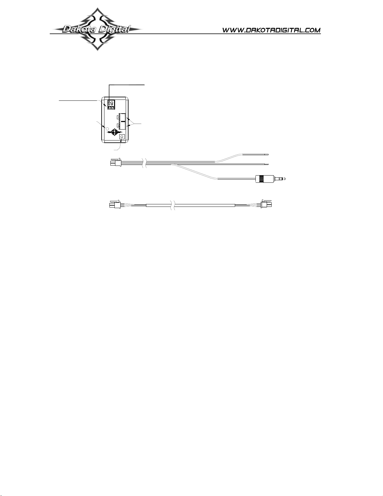
Hold wire release button
when inserting or
removing wires
Connect to the BIM-13-2
if you need to connect to a
BIM-xx-1 or gauge system
(Requires a wide band air/fuel controller with a voltage output)
status light
setup/status switch
BIM-13-2
Bus Interface Module for Air/Fuel ratio
Connect to analog voltage output
from wide band air/fuel controller.
GND REF will not normally be
connected to anything
T
F
U
E
P
R
N
I
D
N
G
BIM-13-2
BIM-xx-2
Power & data connectors
RED WIRE
BIM-xx-1 adapter harness
BLACK WIRE
+12V
KEY ON POWER
(fused 5 - 20 AMP max)
Connect to main
chassis ground
To gauge control box
or BIM-xx-1
Connect to the BIM-13-2
if you need to connect to a
BIM-xx-2
BIM-xx-2 18 inch power/data harness
Connect directly to
another BIM-xx-2
This Bus Interface Module has one input to monitor the air/fuel ratio output from a wide band air/fuel controller with an
analog voltage output. It is programmable to provide either an air/fuel ratio display or a lambda display. The module can
be programmed to work with different scaling values of a voltage between 0 – 5 volts. This allows it to be set for nearly
any wide band system available. There are two interface (I/O) ports on the module. Either one can be connected to the
gauge system or to another module, allowing several units to be daisy chained together. Do not connect the I/O port to
anything other than a Dakota Digital gauge or BIM. Do not mount the module in the engine compartment; it should be
mounted in interior of the vehicle.
Each unit connected to the bus needs a unique ID number assigned to it. The unit comes preset with an ID value that
should not conflict with any other BIM connected to your system. If needed the ID can be automatically reset to an
unused value.
Label for the input is:
AIR/FUEL - voltage input. This will display A-F, AF, A/F, or AIR/FUEL.
Specs for each input mode are:
Mode Range Resolution 0V setting 5V setting
Air / Fuel A-F ratio 0 – 5.00 V 0.1 00.0 – 12.6 4.4 – 74.0
Air / Fuel lambda 0 – 5.00 V 0.01 0.00 – 0.63 1.00 – 5.00
Common LO and HI settings for popular analog output signals:
Consult your wide band air fuel installation and operation manual for details on the type of analog output provided.
Output type A/F LO A/F HI Lambda LO Lambda HI
10 = 1.0V, 20 = 2.0V 0.0 50.0 0.00 3.40
0 = 0.0V, 50 = 5.0V 0.0 50.0 0.00 3.40
9 = 0.0V, 16 = 5.0V 9.0 16.0 0.61 1.10
7.35 = 0.0V, 22.39 = 5.0V 7.4 22.4 0.50 1.50
Lambda 0.5 = 0.5V, 1.5 = 1.5V 0.0 74.0 0.00 5.00
8.5 = 0.5V, 18 = 4.5V 7.4 19.2 0.50 1.30
Different fuel types will require different scaling values for the air fuel ratios. Consult your wide band air fuel installation
and operation manual for more details on using different fuel types.
(WARN LO) (WARN HI)
MAN #650505b

To change between Air / Fuel and lambda readings:
• Turn the key on so the gauge and BIM-13-2 are powered.
• Press and hold the setup/status switch on the BIM-13-2. The status light will slowly flash red and green.
• After about 10 seconds the status light will begin flashing rapidly. Release the switch.
• The reading will now be changed.
To set or change the ID number:
The ID will not normally need to be changed. A green-red-red flash on the BIM-13-2 status light indicates an ID
conflict with another connected BIM. The following procedure will allow the BIM-13-2 to automatically select a new,
unused ID.
• Press and hold the setup/status switch on the BIM-13-2 while turning the key on. The BIM status light will be
steady RED.
• Release the switch.
• When the status light begins flashing, it is finished.
This module does not use warning points, so the warning setup is used to program the display range matching
your wide band controller analog output. These settings are changed on the gauge system display. Common
settings are listed on the front page of the manual.
Only VFD3/3X controls with a plastic case support adding BIM’s.
For VFD3, VFD3X, and VHX systems follow these steps:
• Make sure the BIM units are all connected to the gauge control box.
• Hold the SW1 switch from the gauge system control box while turning the key on. The message display should
show SETUP.
• Release SW1.
• Press and release SW1 until BIM is shown on the message display.
• Press and hold SW1. The message display should show SCAN followed by the number of BIM channels
detected. Release SW1.
• If 0 is shown, check all connections and then press and hold SW1 with SCAN shown to retry reading the modules.
• Otherwise, if any other number is shown, press and release SW1 until SETUP is shown.
• Press and hold SW1 until the speed display shows “ – ” or the message changes.
• Release SW1. On the VFD3 systems the message display will show the label assigned to the first channel found
and the speed display will show “C” followed by the channel ID number. On the VHX systems the message
display will show “CH” followed by the channel ID number on one line and the label currently assigned on the
second line.
• Press and release SW1 until the desired channel ID number is shown.
• Press and hold SW1. The message display will show “LABEL”.
• Release SW1. The message display will show the label assigned to this channel.
• This label cannot be changed, so press and hold SW1. The message display will show “WARN”.
• Release SW1. The message display will show “L” followed by the current 0 volt display setting.
• Press and release SW1 to change the 0 V display setting to the desired value.
• Press and hold SW1 until the speed display shows “ – ”.
• Release SW1. The message display will show “H” followed by the current 5 volt display setting.
• Press and release SW1 to change the 5 V display setting to the desired value.
• Press and hold SW1. The message display will now show “DONE”.
• This can be repeated for additional channels, or the key can be turned off to exit setup.
MAN #650505b
 Loading...