

Page 1
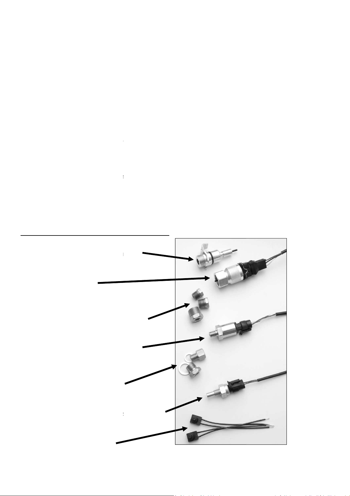
Dakota Digital Sensor
Pack
akota Digital Part Number 393050
sensor kit, supplied with all Dakota Digital
harnesses needed to complete
allow simpler installation into various applications.
oil pressure and water temp sensor provided in this kit MUST be used with your Dakota Digital display
other aftermarket sensors will result in incorrect readings, gauges not working at all, or
akota Digital control module
cable driven applications to convert to an electronic signal.
or have an ECM that provides a
A
accept a wide range of stock sensors as well as a custom ca
part number
commonly used
s
additional adaptors, fittings or
brass plumbing fittings from a hardware store
. The threads on the oil pressure a
If necessary, t
includes the following parts
ensor
(Included in certain applications
B
Oil Pressure S
ensor (40
systems
tains an assortment of
. The speed sensor provided can be used for
If you are currently
(VSS)
A
s the Dakota Digital control module
libration for universal installations
installation of its sensor
s
trains they are installed within,
wiring to fit the specific application
provide a simple solution to a unique mounting
nd water temp sensor are 1/8” NPT and
this kit may
D
This universal
sensors and
used adaptor bushings to
The
system, using stock or
damage to the D
speedometer
speed sensor
wired directly to the control module.
offers a universal fuel sensor,
Dakota Digital provides
the universal nature of the system
it may be necessary to source
Typically,
application
other larger sized fittings.
of thread sealant or tape.
age
integrated instrument
the installation. This kit also con
n electronic vehicle speed output
fuel level sensor is not supplied a
SEN-06-1.
hardware to expedite the
and the variety of vehicles and drive
he threads on the sensors in
includes the required
commonly
mechanical
using an electronic
, these signals may be
can
. Dakota Digital
s, but due to
.
easily adaptable to
be sealed with the use
The Sensor Package
Ford Adaptor Cable for Speed S
16,000 PPM Speed Sensor
with harness
1/8” NPT > 1/4”, 3/8”, and 1/2” NPT
0-100 PSI Solid State
with harness
1/8” NPT > 12 and 16 mm Bushings
with crush washers
100-300˚F Isolated Water Temp S
with harness
:
)
ushings
ensor
-150˚C)
Momentary Push Button Switches
MAN#650311
Page 2
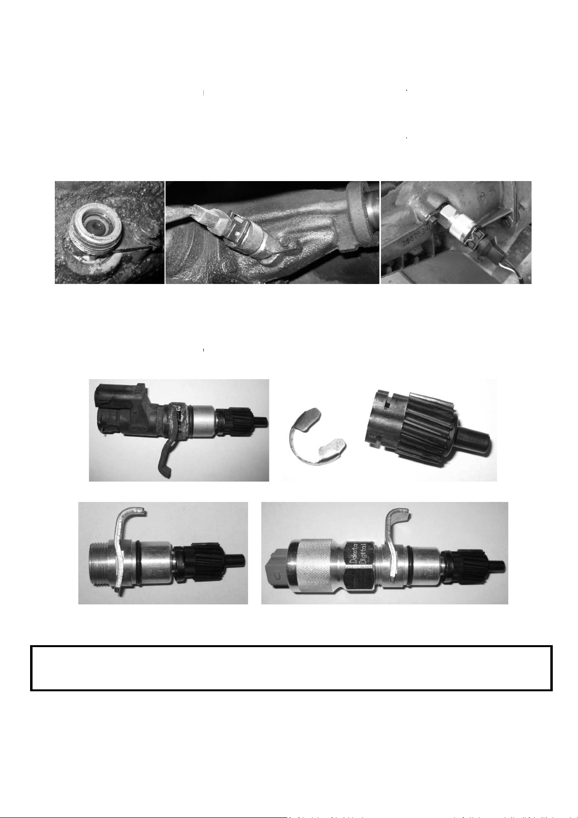
of the speed sensor is generally straight
then simply tighten the new sensor in place making sure that t
the existing speedometer gear. The sensor will thread directly onto a standard GM transmission speedometer
Connect the harness until it “clips” into place
onto the sensor
connector body in only one direction.
Cable (Included in Certain
remove the stock gear from the end of the original speedo
Ford adaptor cable
, making
the new speed sensor onto the
speed sensor removed from
Gear installed on new Ford adaptor
an electronic speed sensor
the speed sensor supplied in this kit
terminal on the
forward. Remove the cable from the transmission if
he square drive shaft on the sensor engages into
to depress the silver wire
The harness is indexed to fit the
meter cable or pulse generator. Once the gear
ord adaptor to the trans
correspond with the mating gears on the
.
Gear and clip removed
New sensor installed on adaptor
or have an
Instead, route
Speed Sensor
Installation
gear that has 7/8”-18 threads.
harness connector while pressing it
. You may need
to lock it in place.
present,
locking clip on the
Ford Adaptor
First,
is removed, install it onto the new
the original attachment screw
transmission. Finally, thread
Original
Model Applications)
. Secure the new F
certain the gears on the adaptor
Ford adaptor cable
transmission
mission using
If you are using
speed output (VSS),
directly to the SPD SND
installed in the transmission
will not be used.
control module.
ECM that provides a vehicle
the speed signal
MAN#650311
Page 3

Most engines have an oil pressure port on the engine block or near the oil filter
separate extension or angled fitting
you may drill and tap the cast
use the supplied 1/8” npt >
side rear of the engine behind the intake manifold.
for the water temp
When installing the temperature sensor, use caution
ng the sensor
Drill / Tap here for
On the rear of a Small Block
Chevy (with use of an
additional extension)
Sensor installed in
assembly
You ma
above the oil filter t
6mm adaptor and replace the stock pressure sensor located
the engine block, cylinder head, or intake
when selecting a mounting location to avoid
ng the sensor
Sensor T’d into oil cooler
Sensor installed on
Sensor installed in
Oil Pressure
require a
cooler line, application permitting.
For LSx based engines,
sensor. Alternatively,
near the driver’s
for proper sensor clearance.
line (with inline adaptor
purchased separately)
metal assembly
1
. Some locations may
y also “T” this fitting into an oil
o accept the 1/8” npt
1/8”-27 NPT. Drill
size of 11/32”
Water Temperature
Typical mounting locations
manifold.
excessive exhaust heat from damagi
intake manifold
oil filter assembly
erature sensor are
.
coolant housing
MAN#650311
Page 4

(Water Temp Cont.)
he use of the supplied 1/8”npt >
First, u
plug toward the rear of the passenger
care when tightening this assembly into the engine
slightly smaller than the
a sufficient amount
The two push button switches supplied in the kit are not
momentary switch can be substituted or used in their place
speedometer calibration, initial set up
switch connects t
The switch installation is covered in greater detail within the instrument cluster
Momentary Switch #1
12mm bushing and crush washer make installation of
tighten the sen
to avoid
and tightening plus
Sensor and harness installed
proprietary to Dakota Digital, a
. These switches are used fo
Odometers along with several other message
the control
Momentary Switch #2
To SW2
on control box
For LSx based engines, t
the water temp sensor simple.
Then, simply remove the allen-head
and sensor in this location.
***Use extreme
1/8” thread is
wrench is typically
sing two wrenches (5/8” and ¾”),
diameter of the 12mm thread, h
.
’s side
sor into the bushing.
head and install the bushing
breaking the bushing. The
¼ turn with a
Allen plug
Push Buttons
displays. One side of each
switch wire attaching to ground.
manual.
To SW1
on control box
Sensor installed
if desired
and for accessing the
o the appropriate location at
Connect to good
chassis ground or
control box GROUND
ny normally open
r
module, with the remaining
4510 W. 61st St. N., Sioux Falls SD 57107
Phone: (605) 332-6513 Fax: (605) 339-4106
www.dakotadigital.com
dakotasupport@dakotadigital.com
©Copyright 2010 Dakota Digital Inc.
MAN#650311
 Loading...