

Dakota Alert WPT-3000 User Manual
Dakota Alert
™
WPT-3000
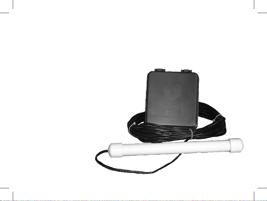
Wireless Probe
Transmitter
Owner’s Manual

2.
Warnings
This device complies with Part 15 of the FCC rules, operation of this device is subject to the
following conditions: 1. This device may not cause harmful interference. 2. This device must
accept any interference, including interference that may cause undesired operation.
Installation:
The WPT-3000 transmitter is used with the Dakota Alert WR-3000 receiver. The WPT-3000
transmitter uses a magnetic probe and 50 feet of direct burial cable to detect vehicles at the
monitored location. When the transmitter detects a vehicle it will send a signal to the receiver
which will sound one of 4 different tones (Classical , Westminster Chime, Ding Dong, Whistle)
for a few seconds. The transmitter can be used to monitor driveways, drive-up windows, etc.
NOTE: Test the WPA-3000 system before burying the probe. Place the probe above ground
where it will be installed, then test it by having a car drive by.
Operation:
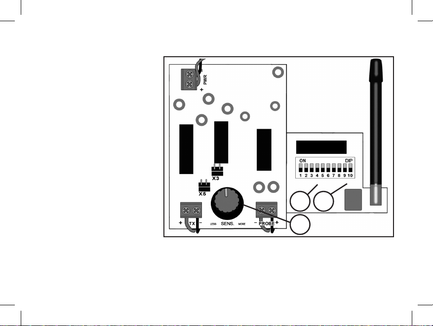
1. Connect a 9 volt alkaline battery to the transmitter. (figure 1)
2. Set the dip switches 1-8 on the transmitter module to match the receiver.
3. Set dip switches 9 &10 to control the desired zone, tune and relay output.
4. Bury the probe next to the driveway and bury the wire over to a tree or post.
5. Mount the transmitter box
on a tree or post about 3 to 4
feet off the ground.
For maximum range between
the transmitter and receiver, the
transmitter should be mounted
on a wooden post or tree (steel
posts may cause interference
with the radio signal). Although
the maximum range is about
3000 feet, things such as hills,
trees, metal siding and stucco
can all reduce the range.
Coding the transmitter:
1. Locate the dip switches in
the WPT-3000 transmitter.
2.
The first 8 dip switches are for the
frequency setting (256 combinations) (figure 1).
Set the first 8 switches to match the 8 switches in the receiver.
3.
figure 1
1
2
{
{
3
 Loading...