

Dakota Alert WHT-3000 User Manual
Dakota Alert
™
WHT-3000
Wireless
Rubber Hose
Transmitter
Owner’s Manual

2.
Warnings
This device complies with Part 15 of the FCC rules, Operation of this device is subject to the
following conditions: 1. This device may not cause harmful interference. 2. This device must
accept any interference, including interference that may cause undesired operation.
Installation:
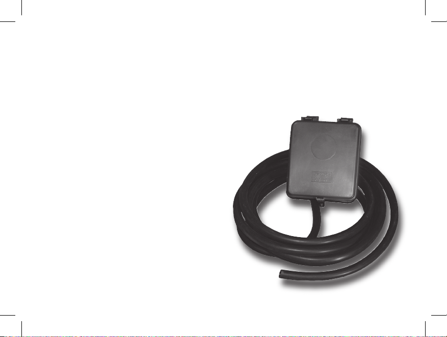
The WHT-3000 transmitter consists of a transmitter box and 25 feet of hose. To install, connect
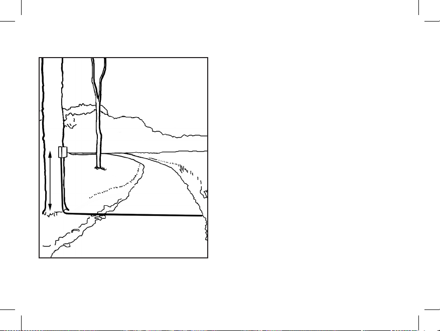
the hose to the stem on the transmitter box, then lay the hose across the driveway. Mount
the transmitter box on a tree or wooden post about three to four feet off the ground (see
figure 1). Avoid using steel posts as this may interfere with the radio signal. The maximum
range of the system is about 3,000 feet, however, obstructions such as hills, trees and metal
siding can reduce the range.
Connect a 9-volt alkaline battery to the transmitter. The battery should last about 6 to 12
months under normal conditions. Once the battery is connected, the system will need a few
seconds to warm up. After this time the transmitter will detect vehicles driving over the hose.
Make sure that there are no kinks in the hose, as this may keep the transmitter from detecting.
When the transmitter detects a car, it will send a signal to the receiver, which will sound one of
four different tones (Classical, Westminster Chime, Ding Dong, or Whistle) for a few
seconds.
3.
Operation:
The control box is powered by one 9-volt battery.
Coding the transmitter:
1.
Open the transmitter box. The first thing you
will see is the air switch (Figure 2). Directly
below the air switch is the
transmitter’s
radio (Figure 3).
2. Locate the dip switches on the radio .
3.
Switches 1-8 are for the frequency setting
(256 combinations). They are set at the
factory to the on position in both the
receiver and transmitter. If needed, set
switches 1-8 , to match the eight switches
in the receiver.
4. Switches 9 and 10 are for the channel
setting on the transmitter. Use these to set
the tone you prefer. The four channels are
listed in the table on page 5:
figure 1
3 to
4 ft
 Loading...