

Dakota Alert UT-3000 User Manual
UT-3000
Universal
Transmitter
Owner’s Manual
Dakota Alert
™

2.
Warnings
This device complies with Part 15 of the FCC rules, Operation of this device is subject to the following conditions: 1. This device may not cause
harmful interference. 2. This device must accept any interference, including interference that may cause undesired operation.
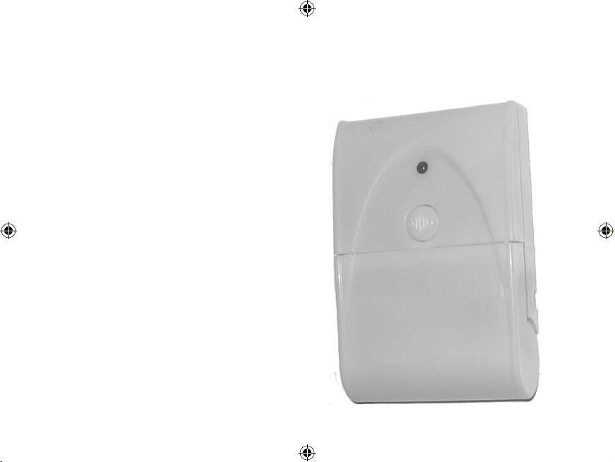
Introduction
The UT-3000 transmitter is compatible with any 3000 Series receiver.
The UT-3000 has several methods of activation. First, it has a push button that can be used as a panic button or doorbell. The UT-3000 also
has terminals for a normally open (N/O) or normally closed (N/C) input.
These inputs can be used with any detector contacts. When the transmitter is activated, it will send a signal to the receiver which will sound
one of four different tones (Classical, Westminster Chime, Ding Dong, or
Whistle) for a few seconds, or activate the relay outputs.
Operation:
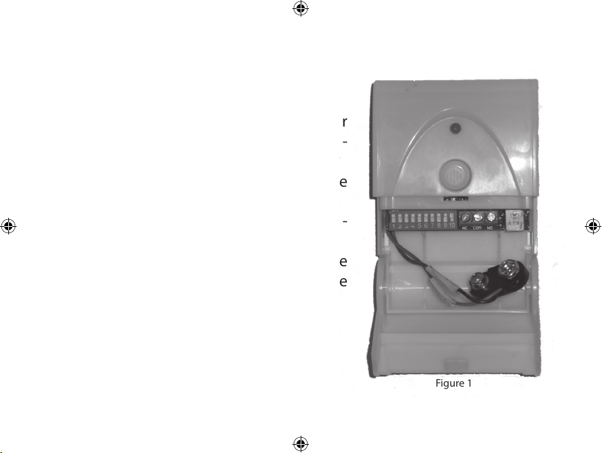
1. Swing open the bottom of the front cover
to reveal the battery connector, dip switch-
es and input terminals. (see Figure 1)
2. Connect a 9-volt alkaline battery to the
transmitter.
3. Set the dip switches 1-8 on the transmit-
ter module to match the receiver.
4. Set dip switches 9 and 10 to control the
desired zone, tune, and relay output. (See
Coding the transmitter for info on setting
the dip switches.)
3.
Figure 1
Operation:
1. Swing open the bottom of the front cover
to reveal the battery connector, dip switch-
es and input terminals. (see Figure 1)
2. Connect a 9-volt alkaline battery to the
transmitter.
3. Set the dip switches 1-8 on the transmit-
ter module to match the receiver.
4. Set dip switches 9 and 10 to control the
desired zone, tune, and relay output. (See
Coding the transmitter for info on setting
the dip switches.)
 Loading...