

Dakota Alert UT-2500 Owner's Manual

www.bealert.co.nz www.bealert.com.au
NEW ZEALAND AUSTRALIA
WARNING:
This device complies with Part 15 of the FCC rules, operation of this device is subject to the following conditions:
1. This device may not cause harmful interference.
2. This device must accept any interference, including interference that may cause undesired operation.
UT-2500
Universal Transmitter
Owners Manual
INTRODUCTION
The UT-2500 transmitter is compatible with the DCR-2500 receiver. The UT-2500 has several methods of
activation. First, it has a push button that can be used as a panic button or doorbell. The UT-2500 also has
terminals for a normally open (N/O) or normally closed (N/C) input. These inputs can be used with any detector
contacts. There is also a magnetic contact that can be used for doors or windows. When the transmitter
is activated, it will send a signal to the receiver which will sound one of four different tones (Classical,
Westminster Chime, Ding Dong, or Whistle) for a few seconds, or activate the relay outputs.
OPERATION:
(Always test unit prior to installation)
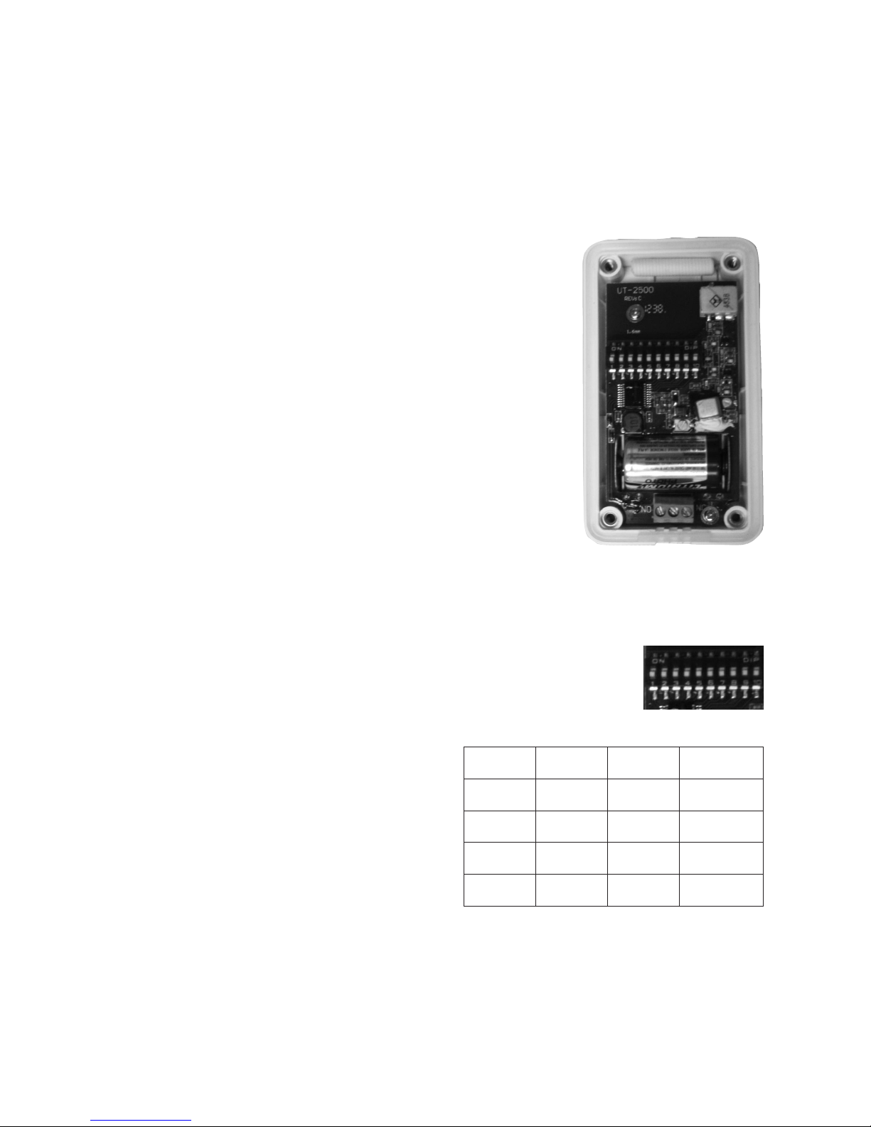
1. Remove the four screws on the back of the case and open to
find the battery compartment and dip switches. (Figure 1)
2. Install the CR-2 battery in the holder.
3. Set the dip switches 1-8 on the transmitter module to match
the receiver.
4. Set dip switches 9 and 10 to control the desired zone, tune, and
relay output. (See Coding the transmitter for info on setting the
dip switches.)
INSTALLING THE BATTERY:
1. Use only a CR-2, 3 Volt Lithium battery.
2. Be sure to observe proper polarity when installing the battery.
LED INDICATOR LIGHT IN BUTTON:
1. The default setting is for the LED indicator to light up for two
seconds when the UT-2500 is activated.
2. To deactivate the LED, press and hold the push button while installing the battery.
3. To return to the default LED setting remove the battery and then re-install the battery.
CODING THE TRANSMITTER:
1. Open the transmitter.
2. Locate the 10 dip switches in the transmitter (Figure 2).
3. The first eight dip switches are for the frequency
setting (256 combinations). Set switches 1-8 to
match the eight switches in the receiver.
4. Switches 9-10 are for the zone/channel setting on
the transmitter. The four zones are detailed in the
table oppposite.
5. After any changes are made to the dip switches,
the battery must be disconnected and then
reconnected for changes to take effect.
Switch 9 Switch 10 Channel Tune
On On 1 Classical
Off On 2 Westminster
On Off 3 Ding Dong
Off Off 4 Whistle
FIGURE 1
FIGURE 2
 Loading...