

Page 1
CAD-05 Kit GSM
Auto Dialer
Owner’s Manual
CAD-05 Kit Manual.indd 1 10/15/2009 9:40:53 AM
Page 2
2 3
Warnings:
This device complies with Part 15 of the FCC rules, Operation of this device is subject to the following conditions: 1. This device may not cause harmful interference. 2. This device must accept
any interference, including interference that may cause undesired operation.
Features:
Wireless alarm; no telephone line required, GSM Dialer supports any standard SIM card; programmable entry/exit delay time; two separate dialer alarms, alarm and panic; select up to 9 (32 digit)
user programmable phone numbers for each alarm; dierent 10 second recordable message for
each alarm; arm/disarm using keypad or remote keyfob; wireless panic; built-in tamper switch;
built-in terminal block for alarm and siren connection; DC adaptor with rechargeable battery
back-up; programmable as silent alarm (dialer only) or audible (siren + dialer).
Contents:
1 - GSM Auto Dialer
2 - RF PIR Sensor
1 - RF Keyfob
1 - 9V 500mA DC Adaptor
1 - Installation & Programming Guide
1 - Rechargeable 7.2V Battery
CAD-05 Kit Manual.indd 2 10/15/2009 9:40:53 AM
Page 3

IMPORTANT
Before you install the PIR Detectors, please take these points into consideration:
Don’t position the detectors facing windows.
Don’t position in direct sunlight.
Don’t position above heat sources or in areas of moisture.
Don’t let pets roam into the detection area when the system is armed.
The PIR Sensor is set to Alarm 2 so take this into account
when you are programming your voice messages.
Opening the PIR Sensor to access dipswitches and battery connector:
1. Slide the PIR Sensor o the bracket (use the bracket as a template for mounting.)
2. Using a small standard screwdriver, press the release clip on the bottom of the PIR Sensor.
3. Separate the two parts.
Opening the RF Keyfob (only necessary when it is time to change the battery):
1. Using a small Phillips screwdriver, remove the screw from the back of the keyfob.
2. Take a small standard screwdriver and place in groove seperating the two keyfob halves.
3. Slowly twist and the keyfob housing should separate.
CAD-05 Kit Manual.indd 3 10/15/2009 9:40:53 AM
Page 4
4 5
Installation
Tools: Small & Large Phillips Screwdrivers; Small Standard Screwdriver.
Set Up:
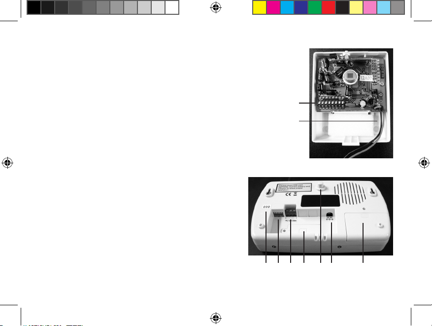
1. Set PIR and CAD-05 dipswitches to match. The rst ve dipswitches
on both units (Figure 1-1 and Figure 2-1) need to be set exactly the
same with the last 3 dipswitches on the PIR sensor (Figure 1-1)
matching the 3 numbers on the sticker to the left of the dipswitches
on the dialer (Figure 2-2). (Note: On the PIR sensor, “o” is in the down
position. On the Dialer, “o” is in the up position.)
2. Install battery in PIR sensor (Figure 1-2) and mount at desired
location. (Note: recommended to replace batteries every 6 months.)
3. Use a small Phillips screwdriver to loosen SIM card
cover on dialer (Figure 2-3). Lift up on hinges. Slide
black cardholder to the left and lift. Insert SIM card
into the cardholder with the notch on the top (Figure
3). Close cardholder and slide to the right to lock into
place. Close cover and tighten screw.
4. (Note: please read all of step 4 before continuing).
Remove the battery insulator by pulling the tab on
the keyfob. Plug the DC adaptor into the dialer (Figure
2-5) and plug into wall outlet. Wait 20 seconds. If your
Figure 1
1
2
Figure 2
2 1 7 3 6 5 4
CAD-05 Kit Manual.indd 4 10/15/2009 9:40:53 AM
Page 5
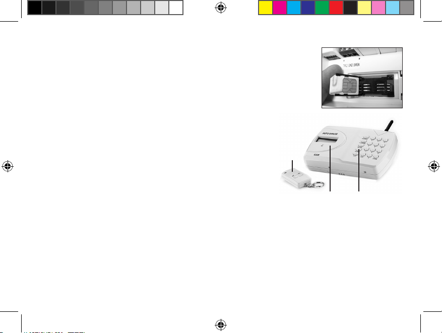
SIM card is properly installed, you will see a telephone symbol on the
display (Figure 4-2). You now have 30 seconds to teach the dialer. Press
the RECORD button (Figure 4-3) on the dialer and the display will show
“learning 0.” Press any key on the RF Keyfob. The display will then show
“learning 1” followed by a BEEP to conrm that it has learned the rst
keyfob. You then have another 30 seconds to teach it another keyfob
(“learning 2”) and so on up to 5 keyfobs.
5. (Note: Tamper switch (Figure 2-6) arms automatically when
depressed and will cause alarm 1 to activate when released.
Disarm by entering password code 1234 into dialer followed by
the ESC button or by using the OFF button on the keyfob). Install
the back-up battery (included) into the dialer. Use a small
Phillips screwdriver to remove screw above battery cover
(Figure 2-4). Remove cover by sliding downwards. Plug in
battery pack making sure not to force onto pins incorrectly.
Put battery pack in space provided, close battery cover, and replace the screw.
6. The dialer also has a terminal block (Figure 1-7) which has a normally open trigger input and a
12V, 150mA (maximum) output. Any sensor with a normally open output can be connected to the
TR2 and GND terminals and can be used to trigger the dialer. Any 12VDC siren or whistle can be
attached to the GND and SIREN terminals and will sound when the dialer is triggered.
7. Continue on to the Advanced Operations to program your dialer or refer to the “CAD-05 Quick
Reference Programming” on page 14.
Figure 3
Figure 4
1
2
3
CAD-05 Kit Manual.indd 5 10/15/2009 9:40:53 AM
Page 6

6 7
Advanced Operations
HOW TO PROGRAM THE AUTO DIALER
*If no key is pressed for 30 seconds, the dialer will automatically exit the programming mode.
Notice: The system must be in the OFF mode for all programming.
How to record the voice messages:
Alarm 1 = Tamper and panic alarm. Alarm 2 = PIR sensors and hard-wired input.
1. Key in the four digit user password code (factory default is 1234.)
2. Press RECORD.
3. Press 1 (to save as the message for alarm 1) or 2 (to save as the message for alarm 2).
4. Press ENTER to start recording your 10 second message.
5. Press ENTER to stop the recording early or wait for the 10 seconds to end.
Quick guide: Press 1 2 3 4 > RECORD > 1 > ENTER, record message now
How to play back the message:
Press 1 2 3 4 > PLAY > 1 > ENTER to play back the recorded message.
(Notice: 1 = the rst message, 2 = the second message).
How to program phone numbers:
You can enter a maximum of nine telephone numbers for the alarms. Each number can be
a maximum of 32 digits. (If you are using this Auto Dialer on an oce/work phone system
you may have to enter 9 before the number to get a line out.)
CAD-05 Kit Manual.indd 6 10/15/2009 9:40:53 AM
Page 7

1. Key in the four digit user password code (factory default is 1234.)
2. Press PROGRAM > 3 > ENTER.
3. The number you press next will select the position in the sequence you want that
telephone number to dial (1 = rst number called, 2 = second number called, and so on).
4. Press ENTER and key in the rst telephone number.
5. Press ENTER to exit the programming mode.
6. Repeat the process until you have entered all the numbers you wish the Auto Dialer to
call once it has been activated (maximum 9 dierent numbers.)
Quick guide: Press 1 2 3 4 > PROGRAM > 3 > ENTER > 1 > ENTER > Telephone # > ENTER
How to delete phone numbers:
1. Key in the four digit user password code (factory default 1234.)
2. Press PROGRAM > 3 > ENTER.
3. Press N (N = 1 for the rst number called; 2 for the second number called; etc.)
3. Press ESC to exit the programming mode.
Quick guide: Press 1 2 3 4 > PROGRAM > 3 > ENTER > N > ESC
How to designate telephone numbers to ALARM 1 and ALARM 2:
1. Key in the four digit user password code (factory default 1234.)
2. Press PROGRAM > 6 > ENTER.
3. Press X (X = 1 for alarm 1; 2 for alarm 2). Press ENTER.
4. Press N (N = 1 for rst phone number; 2 for second phone number, etc.). Press ENTER.
5. Repeat the process to designate any other numbers to each alarm.
Quick guide: Press 1 2 3 4 > PROGRAM > 6 > ENTER > X > ENTER > N > ENTER
CAD-05 Kit Manual.indd 7 10/15/2009 9:40:53 AM
Page 8

How to change the user password code (factory default is 1234):
1. Key in the four digit user password code (factory default 1234.)
2. Press PASSWORD
3. The LCD will change to n-p.
4. Key in your new four digit user password code.
5. The LCD will change to c-p.
6. Key in your new four digit user password code again.
7. The LCD will change to acc.
Quick guide: Press 1 2 3 4 > PASSWORD > New Code > Conrm New Code
How to program the Auto Dialer to give an audible alarm as well as sending a voice
message (factory default is alarm ON):
1. Key in the four digit user password code (factory default 1234.)
2. Press PROGRAM > 1 > ENTER
3. Press N (N = 0 for without audible alarm, 1 for with audible alarm). Press ENTER.
Quick guide: Press 1 2 3 4 > PROGRAM > 1 > ENTER > N > ENTER
How to set the time the alarm will sound on activation (default time is 3 minutes):
1. Key in the four digit user password code (factory default 1234.)
2. Press PROGRAM > 2 > ENTER
3. Press Time (Time = 1 for one minute, 2 for 2 minutes, etc. up to 99 minutes). Press ENTER.
Quick guide: Press 1 2 3 4 > PROGRAM > 2 > ENTER > Time > ENTER
8 9
CAD-05 Kit Manual.indd 8 10/15/2009 9:40:53 AM
Page 9

How to set Entry/Exit Delay times (default both delay set at 30 seconds):
The entry/exit times are the times the Auto Dialer gives you to enter/exit the area covered
by the system before it arms/alarms. These are pre-set to 30 seconds. You can also change
the timing to instant or 60 seconds.
Entry Delay:
1. Key in the four digit user password code (factory default 1234.)
2. Press PROGRAM > 4 > ENTER
3. Press N (N = 0 for instant; 3 for 30 seconds; 6 for 60 seconds). Press ENTER.
Quick guide: Press 1 2 3 4 > PROGRAM > 4 > ENTER > N > ENTER
Exit Delay:
1. Key in the four digit user password code (factory default 1234.)
2. Press PROGRAM > 5 > ENTER
3.
Press N (N = 0 for instant; 3 for 30 seconds; 6 for 60 seconds; 9 for 90 seconds). Press ENTER.
Quick guide: Press 1 2 3 4 > PROGRAM > 5 > ENTER > N > ENTER
How to set an Entry/Exit delay sound (factory setting Entry/Exit delay with sound):
1. Key in the four digit user password code (factory default 1234.)
2. Press PROGRAM > 7 > ENTER
3. Press N (N = 0 without sound; 1 with sound). Press ENTER.
Quick guide: Press 1 2 3 4 > PROGRAM > 7 > ENTER > N > ENTER
CAD-05 Kit Manual.indd 9 10/15/2009 9:40:53 AM
Page 10

10 11
How to disable Tamper Function (factory setting Tamper ON):
1. Key in the four digit user password code (factory default 1234.)
2. Press PROGRAM > 8 > ENTER
3. Press N (N = 0 without tamper function; 1 with tamper function). Press ENTER.
Quick guide: Press 1 2 3 4 > PROGRAM > 8 > ENTER > N > ENTER
HOW TO OPERATE THE AUTO DIALER
How to Arm the Alarm System/Turn the Dialer ON:
1. Check that the voice message and at least one phone number has been programmed
into the Auto Dialer.
2. Press 1 2 3 4 > ENTER or press the ‘ON’ button on the RF Keyfob. The Auto Dialer will
show ‘ON’ on the display.
3. The alarms will become active after the delay time you have set has expired.
Quick guide: Press 1 2 3 4 > ENTER or Press the ‘ON’ button on the RF Keyfob
How to disarm the Alarm System/Turn Dialer OFF:
To disarm the Alarm System or to stop the Dialer from dialing out after either the tamper
switch (if connected and active) or a alarm input has been activated, key in the four digit user
password code followed by ESC. Alternatively, press the ‘OFF’ button on the RF Keyfob. The
Auto Dialer will revert to the ‘OFF’ mode and must be re-set to the ‘ON’ mode as above.
Quick guide: Press 1 2 3 4 > ESC or Press the ‘OFF’ button on the keyfob
CAD-05 Kit Manual.indd 10 10/15/2009 9:40:53 AM
Page 11

How to stop the Dialer from dialing the telephone numbers in sequence:
When the Auto Dialer starts dialing, it will dial the rst telephone number and repeat the
pre-recorded voice message for 1 minute. If there is no response from the phone, then it
will hang up and dial the next number until all the programmed numbers for that alarm are
dialed. It will repeat this dial sequence three times and display ‘NO ANSWER’ if there is no
response from any of the phone numbers. To stop this dial sequence, press the * key on the
telephone keypad that is receiving the call. At that time, the Auto Dialer will stop its dialing
sequence and the alarm (if programmed) will stop. If the local alarm has been programmed
as active, then pressing the # key will stop the dialing sequence, but the alarm will continue
to sound until timed out. In both cases, the Auto Dialer will remain ON, waiting for any
further alarm.
Quick guide: Answer the phone and press # or * to stop dialing sequence.
How to put the system into PANIC ALARM:
Press both the ON and the OFF buttons on the RF Keyfob at the same time, for 3 seconds.
The dialer will now dial out (Alarm 2) whether the system is armed or disarmed.
CAD-05 Kit Manual.indd 11 10/15/2009 9:40:53 AM
Page 12

12 13
How to change the back-up battery:
Important: It is recommended to change the back-up battery at least once a year, even if
the battery is not low.
1. First make sure that the Auto Dialer is OFF. Then release it from the wall.
2. Remove the battery door and take out the old battery. Insert new 7.2V rechargeable
battery pack and make sure it is in the correct polarity.
3. Fit the battery door and mount the Auto Dialer back onto the wall.
IMPORTANT: SIM Card
Most pay-as-you-go SIM cards will need to be topped up during the rst 3 months of use.
If you do not carry this out, some service providers switch o the SIM card. We recommend
that you alarm the unit as a test every four weeks, just to be sure the SIM card is still
operating.
If the SIM card is pin protected, you will have to enter the pin number when you rst power
the system up. You will have to enter the correct pin number within 3 attempts, otherwise
the SIM card will lock out and you will need to request a PUK number from your service
provider.
Please contact SIM card service provider (AT&T, T-Mobile, RebelFone, O2Wireless, etc.) with
questions reguarding SIM cards. Services may be limited by your local provider. Please
contact them reguarding local limitations.
CAD-05 Kit Manual.indd 12 10/15/2009 9:40:53 AM
Page 13

HOW TO RESET THE AUTO DIALER
Inside the battery compartment:
Remove the power supply and the Auto Dialer from the wall. Remove the 7.2V battery. Then
remove the SIM card. Inside the battery compartment is a switch. Move it to the ERASE
position. Connect the power to the Auto Dialer then press DELETE twice. There will be 2
short beeps from the Auto Dialer. Switch the power o again. Replace the SIM card, place
switch back to NORMAL. Replace the 7.2V battery and place back onto the wall. Power the
Auto Dialer back up. The Auto Dialer will then return to factory default setting.
NOTE AND CAUTION:
A leaking battery will result in poor performance and could damage the system. It is
recommended that the batteries be periodically checked. Change the batteries at least
once a year to maintain the system.
DO NOT mount the Auto Dialer in areas that are exposed to extreme heat or moisture, as
this could adversely aect the performance of the system.
Use only a damp cloth and general household cleaning agent to wipe the unit clean. DO
NOT use turpentine, thinner, gasoline or similar substances to clean the unit.
CAD-05 Kit Manual.indd 13 10/15/2009 9:40:53 AM
Page 14

14 15
CAD-05 Quick Reference Programming
(For step-by-step programming, refer to pages 6-10)
Programming: Enter Pass code 1234; push the Program button; select option number;
1 - Audible Alarm (N = 1-Audible; 0-Silent) 1234>PROGRAM>1>ENTER>N>ENTER
2 - Length of Audible Alarm (N = 1-99 Mins) 1234>PROGRAM>2>ENTER>N>ENTER
3 - Add Numbers (N = 1-9 order in which numbers are dialed)
1234>PROGRAM>3>ENTER>N>ENTER>PHONE NUMBER>ENTER
Delete Numbers (N = 1-9 order in which numbers are dialed)
1234>PROGRAM>3>ENTER>N>ESC
4 - Entry Delay (N = 0 for instant; 3 for 30 secs; 6 for 60 secs; 9 for 90 secs)
1234>PROGRAM>4>ENTER>N>ENTER
5 - Exit Time (N = 0 for instant; 3 for 30 secs; 6 for 60 secs) 1234>PROGRAM>5>ENTER>N>ENTER
6 - Designate phone numbers to alarms (X = 1 for Alarm 1; 2 for Alarm 2.
N = 1-9 order in which numbers are dialed) 1234>PROGRAM>6>ENTER>X>ENTER>N>ENTER
7 - Entrance/Exit Delay Sound (N = 1-Sound; 0-Silent) 1234>PROGRAM>7>ENTER>N>ENTER
8 - Tamper switch on/o (N = 1-On; 0-O) 1234>PROGRAM>8>ENTER>N>ENTER
Recording alarm message: 1234>RECORD>N>ENTER>record message now
(N = 1-Alarm 1 message; 2-Alarm 2 message)
Playing alarm message: 1234>PLAY>N>ENTER
(N = 1-Alarm 1 message; 2-Alarm 2 message)
CAD-05 Kit Manual.indd 14 10/15/2009 9:40:53 AM
Page 15

TECHNICAL SUPPORT
If you encounter any diculty in the operation of this product after reading the manual, please
contact us. You can reach us by phone at 605-356-2772 from 8:30 AM to 5:00 PM Monday through
Friday (Central Standard Time). We will be happy to answer your questions and help you in any
way we can.
WARRANTY
Dakota Alert warrants this product to be free of defects in material and workmanship for a period
of one year from the date of purchase. This warranty does not cover damage resulting from accident, abuse, act of God or improper operation. If this product does become defective, simply
return it to Dakota Alert. Please include a note describing the troubles along with your name and
return address as well as the original sales receipt. If the product is covered under warranty it will
be repaired or replaced at no charge. If it is not covered by warranty, you will be notied of any
charges before work is done.
CAD-05 Kit Manual.indd 15 10/15/2009 9:40:53 AM
Page 16

Dakota Alert, Inc.
32556 E. Main Street
P0 Box 130
Elk Point, SD 57025
Phone: (605) 356-2772
Fax: (605) 356-3662
Web: www.dakotaalert.com
CAD-05 Kit Manual.indd 16 10/15/2009 9:40:53 AM
 Loading...