

Dakota Alert BBT-4000 User Manual
Break Beam
Transmitter
BBT-4000
USER GUIDE
www.dakotaalert.com
TM
Dakota Alert®
WIRELESS SECURITY EQUIPMENT
This BBT-4000 Break Beam Transmitter sends a signal to your DCR-4000 receiver when it detects
moving objects, such as people and vehicles. Connect multiple break beam transmitters (or
other transmitters) to your receiver to create a complete security system.

PACKAGE CONTENTS
• Break Beam Transmitter (2 sensors)
• Mounting hardware
» Right-angle brackets (4)
» Cross brackets (4)
» U-shaped brackets (4)
» M4 × 12 mm bolts (8)
» M5 × 18 mm bolts (8)
» M5 × 27 mm bolts (8)
» M4 nuts (8)
» M5 nuts (16)
• User Guide
Tools needed
• Phillips screwdriver
• Adjustable wrench
SETTING UP YOUR BREAK BEAM DETECTOR
1. Pair the sensors to each other. See “Pairing the sensors” on page 3.
2. Select a tune and code the break beam transmitter to your receiver. See “Coding your
receiver” on page 4.
3. Mount the sensor units. See “Mounting your sensors” on page 5.
2
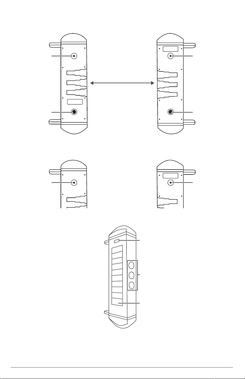
PAIRING THE SENSORS
1. Place sensors A and B on a at surface, 6–12 inches (15.2–30.5 cm) apart, with the three IR
windows on the sides of the sensors facing each other.
B
Power button
6–12 in.
(15.2–30.5 cm)
A
Red plug
2. Press the power button on sensor A until the button lights solid red, then press the power
button on sensor B until the button lights solid red. The sensor units pair. Leave the sensors
in place until both power button lights turn o (about one minute).
B
Power button
on sensor A
Power button
Red plug
Power button
on sensor B
3. Test the transmitter by completely blocking all three IR windows. You should hear a click and
the indicator light in the center window of sensor A lights.
Level
IR windows
Solar panels
3
 Loading...