

Dakota Alert BBT-2500 User Manual
BBT-2500
Break Beam Transmitter
User Guide
www.dakotaalert.com
PRODUCT DESCRIPTION: The BBT-2500 is used with the DCR-2500 receiver. The BBT-2500
uses Active Infrared to detect anything that passes through the sensor pair and breaks both
beams at the same time. When the beams are broken, the unit sends a signal to the receiver.
This will sound one of four dierent tones (Classical, Westminster Chime, Ding Dong, or
Whistle). The BBT-2500 can be used to monitor access into any area, from your backyard to
lumber yard and everything in between.

READ MANUAL THOROUGHLY BEFORE INSTALLATION. RETAIN MANUAL FOR FUTURE
REFERENCE. FAILURE TO FOLLOW DIRECTIONS PROPERLY MAY RESULT IN DAMAGE.
ONLY use this product for the detection of moving objects such as people and vehicles.
DO NOT disassemble or attempt to repair the product.
DO NOT install this unit with any other infrared detector. It may cause false alarms.
DO clean and inspect the unit regularly for proper use. If any problem is found, contact
Dakota Alert, Inc.
WARNINGS: This device complies with Part 15 of the FCC rules, Operation of this device is
subject to the following conditions: 1. This device may not cause harmful interference. 2.
This device must accept any interference, including interference that may cause undesired
operation.
HARDWARE INSTALLATION
Verify that all installation hardware
is included. Tools needed: Phillips
screwdriver, adjustable wrench.
2
(8) M4 nuts
(8) M4x12mm screws
(4) Cross Brackets(4) Right Angle Brackets (4) ‘U’ Shaped Brackets
(8) M5x27mm screws
(16) M5 nuts
(8) M5x18mm screws
PAIRING
To make installation easier
it is recommended to pair
units ‘A’ and ‘B’ before
mounting.
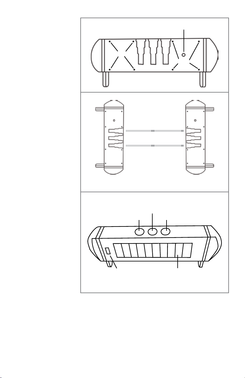
On a at surface push the
power button (Figure 1-1)
on ‘A’ then push the power
button on ‘B’. Laying the
units at on counter or
table, line up the infrared
light holes (Figure 1-2).
The units will then pair.
You will see lights ashing
during this process. Leave
the units in place for one
minute to make sure this
process is complete.
Once paired, test them by
completely blocking all
3 holes (2 infrared light
holes and indicator hole
shown in Figure 1-3).
Unit should send a signal
to the DCR-2500 and
sound an alert. Unit will
only alert if all 3 holes are
completely blocked for at
least 100ms. If an object
passes through the beam
faster than that it will not
be detected.
Back of unit
Front of unit
Power Button
Screws
Screws
Figure 1-1
Place units 6 to 12 inches
apart for pairing
Figure 1-2
Indicator Hole
Infrared Light Hole Infrared Light Hole
‘A’ unit contains the radio
transmitter module.
The ‘A’ unit transmitter
module is factory set to
match the zone 2 setting
of the DCR-2500. It is not
recommended to change
the code setting unless
Figure 1-3
Solar PanelLevel
it is needed to avoid
interference or a dierent
zone is desired. Be careful
when opening this unit to avoid damaging any internal components or wires.
‘B’ unit contains no user serviceable parts. It is not recommended to open this unit.
3
 Loading...