

Dakota Alert AD-01 Kit Owner's Manual

AD-01 Kit
Auto Dialer
Owner’s Manual
AD-01 Kit Manual.indd 1 10/15/2009 10:17:55 AM

2 3
Warnings:
This device complies with Part 15 of the FCC rules, Operation of this device is subject to the following conditions: 1. This device may not cause harmful interference. 2. This device must accept
any interference, including interference that may cause undesired operation.
Features:
Wireless alarm; programmable entry/exit delay time; two separate dialer alarms, alarm and panic;
select up to 9 (32 digit) user programmable phone numbers for each alarm; dierent 10 second
recordable message for each alarm; arm/disarm using keypad or remote keyfob; wireless panic;
built-in tamper switch; built-in terminal block for alarm and siren connection; DC adaptor with
battery back-up; programmable as silent alarm (dialer only) or audible (siren + dialer).
Contents:
1 - Auto Dialer
2 - RF PIR Sensor
2 - RF Keyfob
1 - 12V DC Adaptor
1 - Installation & Programming Guide
1 - Telephone Cable
1 - Back-up Battery
AD-01 Kit Manual.indd 2 10/15/2009 10:17:55 AM

IMPORTANT
Before you install the PIR Detectors, please take these points into consideration:
Don’t position the detectors facing windows.
Don’t position in direct sunlight.
Don’t position above heat sources or in areas of moisture.
Don’t let pets roam into the detection area when the system is armed.
The PIR Sensor is set to Alarm 2 so take this into account
when you are programming your voice messages.
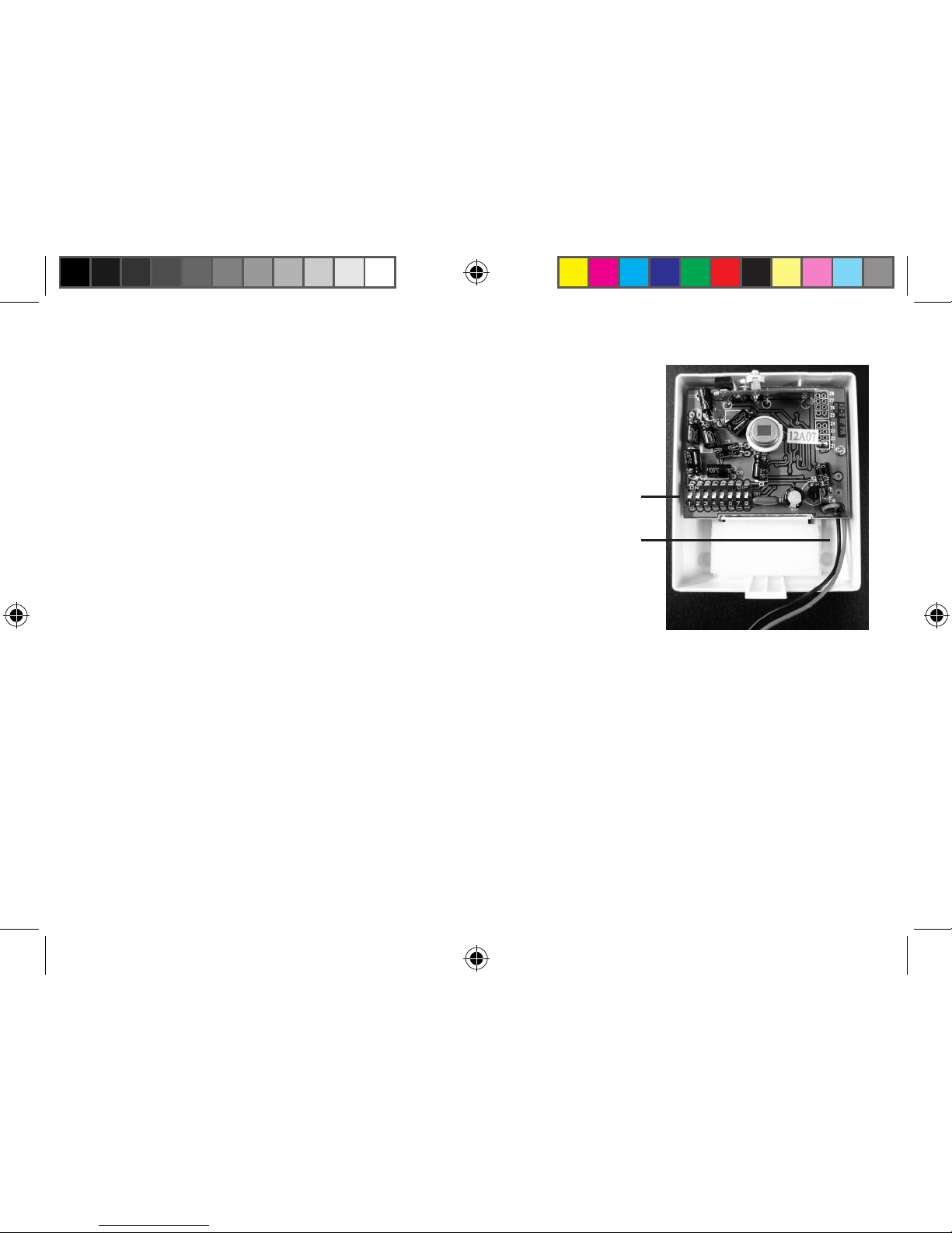
Opening the PIR Sensor to access dipswitches and battery connector:
1. Slide the PIR Sensor o the bracket (use the bracket as a template for mounting.)
2. Using a small standard screwdriver, press the release clip on the bottom of the PIR Sensor.
3. Separate the two parts.
Opening the RF Keyfob (only necessary when it is time to change the battery):
1. Using a small Phillips screwdriver, remove the screw from the back of the keyfob.
2. Take a small standard screwdriver and place in groove seperating the two keyfob halves.
3. Slowly twist and the keyfob housing should separate.
AD-01 Kit Manual.indd 3 10/15/2009 10:17:55 AM
4 5
Installation
Tools needed: Small Phillips Screwdriver;
Large Phillips Screwdriver; Small Standard Screwdriver.
Set Up:
1. Set PIR and AD-01 dipswitches to match. The rst ve
dipswitches on both units (Figure 1 - 1 and Figure 2 - 1) need to
be set exactly the same with the last 3 dipswitches set to “o”.
(Note: On the PIR sensor, “o” is in the down position. On the Dialer,
“o” is in the up position.)
2. Install battery in PIR sensor (Figure 1 - 2) and mount at
desired location. (Note: recommended to replace batteries every
6 months.)
3. Plug the supplied phone cord into the “LINE” jack (Figure 2-5) and then into your home phone
jack. If you wish to connect a phone at the dialer location, you can connect the phone to the
“PHONE” jack (Figure 2-6) on the dialer.
4. (Note: please read all of step 4 before continuing). Remove the battery insulator by pulling the tab
on the keyfob. Plug the DC adaptor into the dialer (Figure 2 - 3) and plug into wall outlet. Wait 20
seconds. You now have 30 seconds to teach the dialer. Press the RECORD button (Figure 3 - 3) on
the dialer and the display will show “learning 0.” Press any key on the RF Keyfob. The display will
then show “learning 1” followed by a BEEP to conrm that it has learned the rst keyfob. You then
have another 30 seconds to teach it another keyfob (“learning 2”) and so on up to 5 keyfobs.
Figure 1
1
2
AD-01 Kit Manual.indd 4 10/15/2009 10:17:55 AM
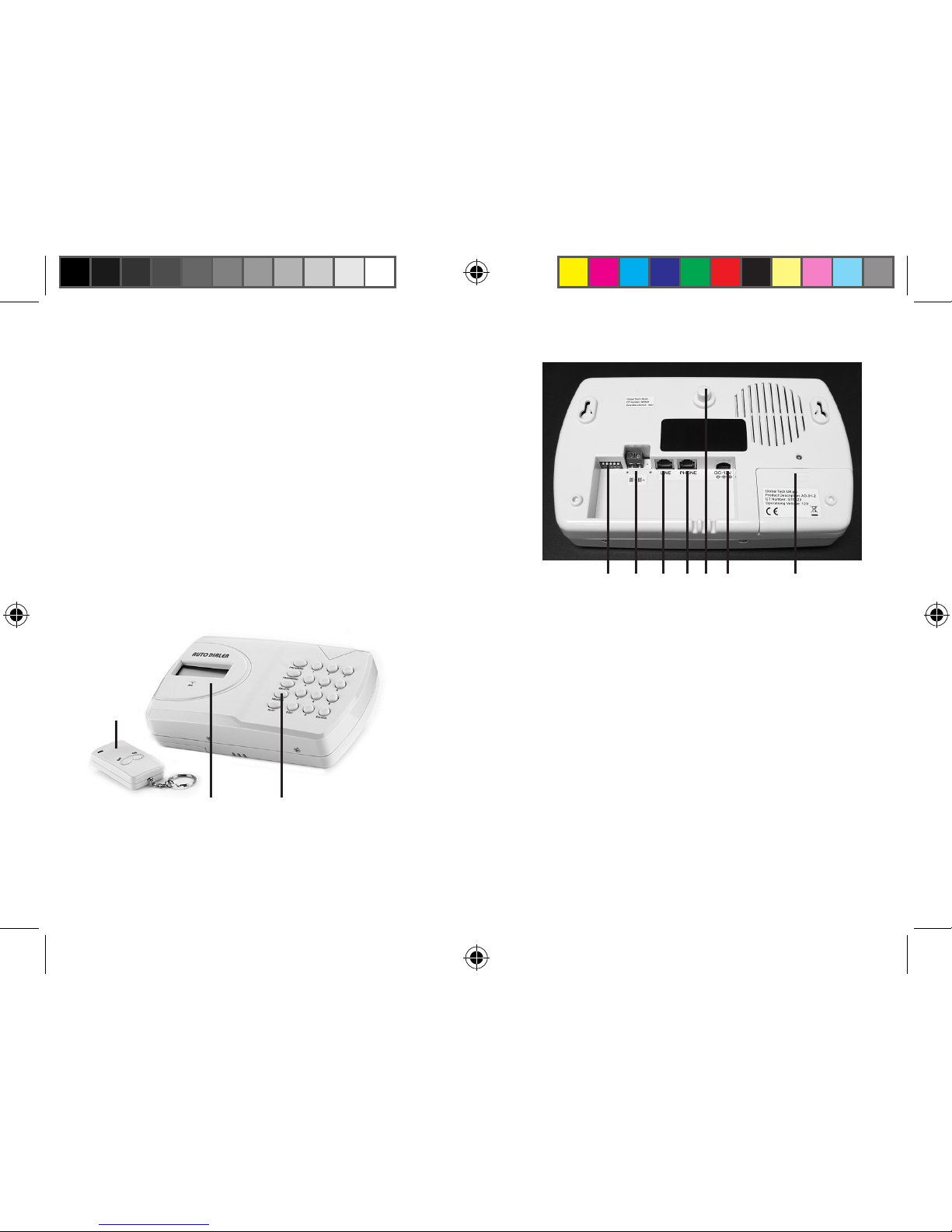
5. (Note: Tamper switch (Figure 2-4) arms automatically
when depressed and will cause alarm 1 to activate
when released. Disarm by entering password code
1234 into dialer followed by the ESC button or by using
the OFF button on the keyfob). Install the back-up
battery (included) into the dialer. Use a small Phillips
screwdriver to remove screw above battery cover
(Figure 2 - 2). Remove cover by sliding downwards.
Plug in 9V battery making sure not to force onto
battery holder incorrectly. Put 9V battery in space
provided, close battery cover, and replace the screw.
6. The BE+ and BE- terminals (Figure 2-7) are a 12VDC,
150mA (maximum) voltage output which can be used
to power an external bell or whistle when the dialer is
activated.
7. Continue on to the Advanced Operations to program
your dialer or refer to the “AD-01 Quick Reference
Programming” on page 14.
Figure 3
1
2 3
Figure 2
1 7 5 6 4 3 2
AD-01 Kit Manual.indd 5 10/15/2009 10:17:55 AM
 Loading...