

Page 1
OPERATION MANUAL
DAKOTA ULTRASONICS
L
DDL
X
CCMMX
Material & Coating Thickness Gauge
P/N P-171-0002 Rev 1.30, April 2008
Page 2

Page 3

CHAPTER ONE INTRODUCTION.......................................................................1
CHAPTER TWO QUICK STARTUP GUIDE........................................................2
CHAPTER THREE KEYBOA RD, MENU, & CONNECTOR REFERENCE.......22
CHAPTER FOUR PRINCIPALS OF ULTRASONIC ME ASUREMENT .............31
CHAPTER FIVE SELECTING THE MEASUREMENT MODE..........................36
CHAPTER SIX MAKING MEASUREMENTS.....................................................39
CHAPTER SEVEN USING THE DIGITS & B-SCAN DISPLAYS ......................55
CHAPTER EIGHT THRU PAINT MEASUREMENT TECHNIQUE....................66
CHAPTER NINE PULSE-ECHO COATING & COATING TECHNIQUES.........67
CHAPTER TEN ADDITIONAL FEATURES OF THE CMXDL.............................82
CHAPTER ELEVEN DATA STORAGE – SETUP, EDIT, & VIEW FILES.........87
CHAPTER TWELVE SETUPS – CREATE, STORE, EDIT, & RECALL..........112
CHAPTER THIRTEEN USI NG THE UTILITY SOFTWARE.............................122
APPENDIX A - VELOCITY TABLE ...................................................................124
APPENDIX A - SETUP LIBRARY.....................................................................126
Page 4

Page 5

CHAPTER ONE
INTRODUCTION
The Dakota Ultrasonics model CMXDL is an ultrasonic thickness gauge that
measures with extreme versatility. It has the ability to measure simultaneously
measure coatings and material thicknesses while maintaining the ability to locate pits,
flaws and defects in the material. Based on the same operating principles as
SONAR, the CMXDL is capable of measuring the thickness of various materials with
accuracy as high as ± 0.001 inches, or ± 0.01 millimeters. The principle advantage of
ultrasonic measurement over traditional methods is that ultrasonic measurements
can be performed with access to only one side of the material being measured.
Dakota Ultrasonics maintains a customer support resource in order to assist users
with questions or difficulties not covered in this manual. Customer support may be
reached at any of the following:
• Dakota Ultrasonics Corporation,
1500 Green Hills Road, #107
Scotts Valley, CA 95066 USA
• Telephone: (831) 431- 9722
• Facsimile: (831) 431-9723
• http://www.dakotaultrasonics.com
1.1 Disclaimer
Inherent in ultrasonic thickness measurement is the possibility that the instrument will
use the second rather than the first echo from the back surface of the material being
measured. This may result in a thickness reading that is TWICE what it should be.
Responsibility for proper use of the instrument and recognition of this phenomenon
rest solely with the user of the instrument. Other errors may occur from measuring
coated materials where the coating is insufficiently bonded to the material surface.
Irregular and inaccurate readings may result. Again, the user is responsible for
proper use and interpretation of the measurements acquired.
Page 6
CHAPTER TWO
QUICK STARTUP GUIDE
Turn the CMXDL on and off using the switch located on the bottom right corner of the
keypad. When CMXDL is initially turned on, a flash logo and blinking lights will be
displayed, followed by attempting to identify the transducer(probe) currently plugged
into the gauge. The CMXDL is equipped with an “Auto Probe Recognition” feature
that attempts to identify special transducers with this built in feature. If the CMXDL
doesn’t find a transducer equipped with this feature, the user will be advanced to a
list of transducers requiring the u ser to select a specific transducer type. The
following sections outline each scenario. Note: This section is primarily written as a
basic startup guide only.
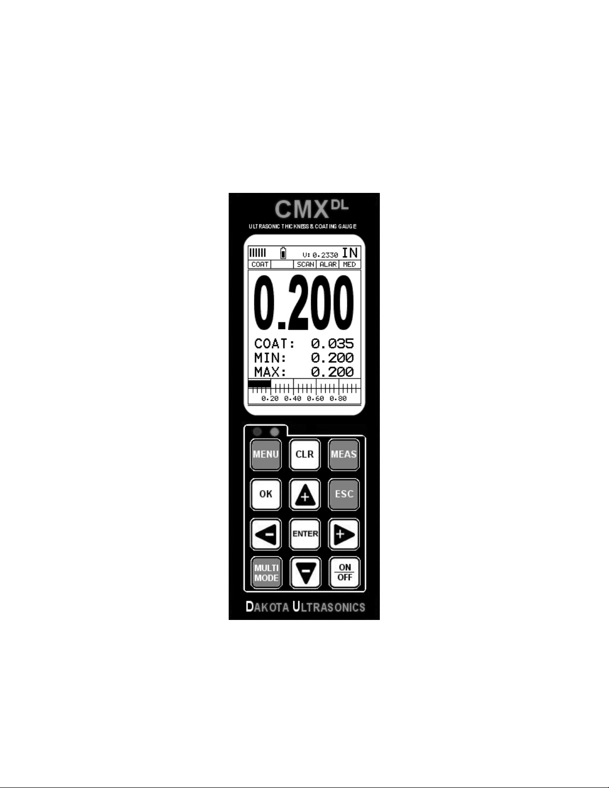
2.1 CMXDL Overview
In order to understand how to operate the CMXDL, it’s best to start off with an
understanding of what it is we’re looking at exactly. The CMXDL has a lot of great
features and tools that will prove to be a huge benefit for the variety of applications
you’re constantly facing on a continual basis. Let’s have a brief look at the screens
you’ll be looking at most often:
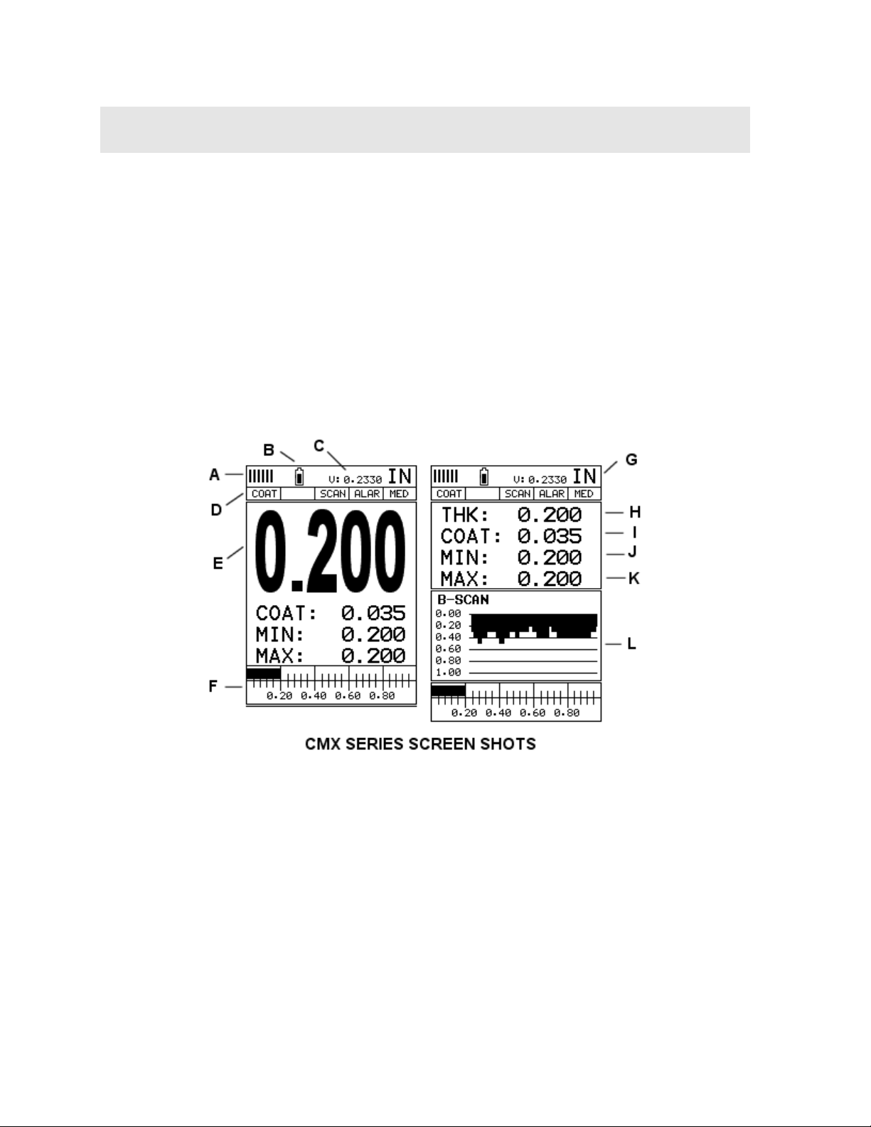
A. Repeatability/Stability Indicator – This indicator should be commonly used
in conjunction with the digital thickness values displayed. When all the vertical
bars are fully illuminated and the last digit on the digital thickness value is
stable, the CMXDL is reliably measuring the same value 3 to 200 times per
second, depending on which measurement mode and features are enabled.
2
Page 7

CMX DL High Performance Material & Coating Thickness Gauge
B. Battery Icon – Indicates the amount of battery life the CMXDL has remaining.
C. Velocity – The material velocity value the CMXDL is currently using or
calibrated for. Displayed in both English or Metric units, depending on the
what units the gauge is set for.
D. Feature Status Bar – Indicates the features currently enabled and in use in
the following order:
• Measurement Mode
• Differential Mode
• High Speed Scan Mode
• Alarm Mode
• Gain Setting
E. Digital Material Thickness Value – Extra large font size for viewing ease.
F. Scan Bar – Another view of material thickness in a deflection style horizontal
bar. This is a visual tool that would enable the user the ability to see thickness
changes during high speed scans from flaws and pits.
G. Units – The current measurement units being used (English, Metric).
H. Digital Material Thickness Value – Smaller font size when the B-Scan
display view is enabled.
I. Coating Thickness Value – Displays the actual thickness of any coating
adhered to a metallic material surface (PECT Mode), or a coating adhered to a
non-metallic surface (CT Mode).
J. Minimum Material Thickness – Part of the Al arm feature. Displays the
minimum thickness value found during a scan.
K. Maximum Material Thickness – Part of the Alarm feature. Displays the
maximum thickness value found during a scan.
L. B-Scan Display – Cross section view of the material. Provides the user with
graphical view of the opposite/blind surface (i.e. inside pipe wall surface), to
give the user some idea of the condition, or integrity of the material being
tested.
3
Page 8
Dakota Ultrasonics
2.2 Auto Probe Recognition
When the CMXDL is initially powered up, the gauge will automatically check to see if
the transducer plugged into the gauge can be recognized. The steps that follow
assume the CMXDL recognized the probe type:
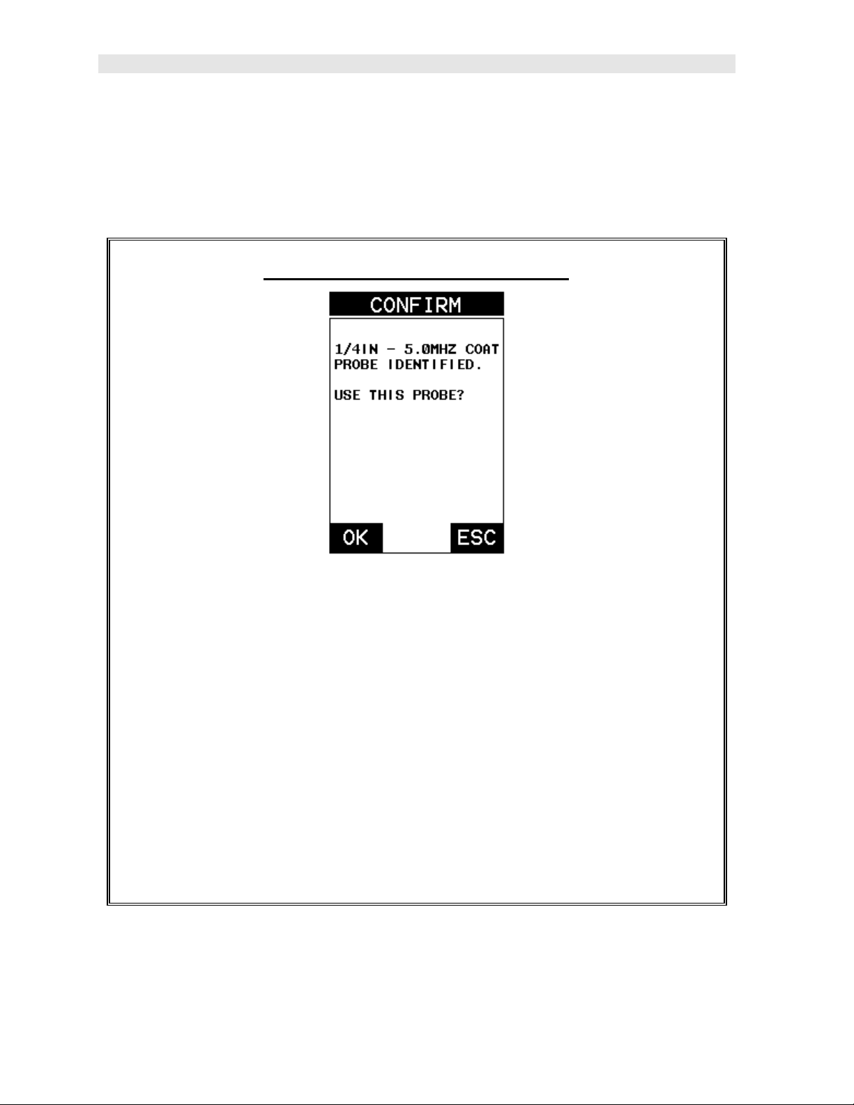
Probe Automatically Recognized
1) Press the OK key once to use the identified probe, or ESC to display a list of
optional transducers. Note: if the CMXDL recognizes a specific transducer,
the user should always select OK to use the identified probe. The only time
an alternative probe should be selected from a list is if the user switched
probes following initial power up and recognition.
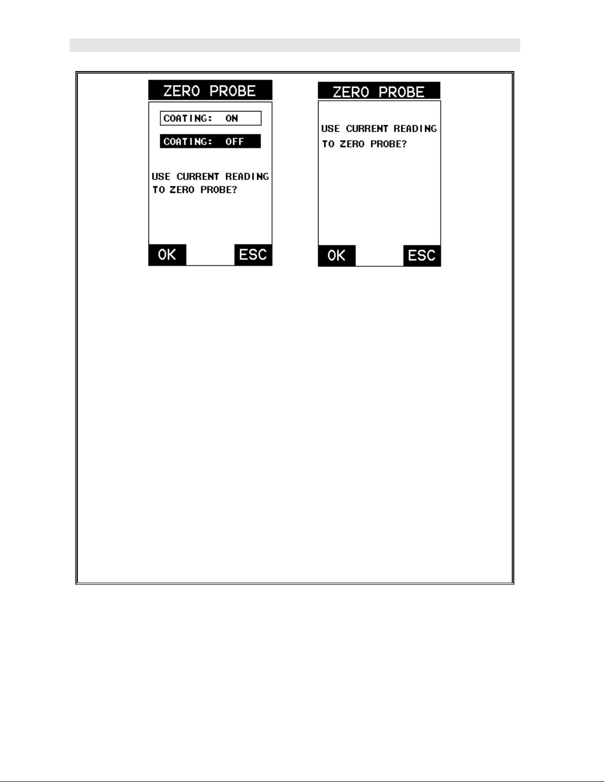
2) Assuming the CMXDL recognized the probe and the OK key was pressed,
the CMXDL will advance to a Zero Probe menu. If the transducer was
identified as a special transducer capable of measuring coating thickness, a
menu will be displayed allowing the user the ability to toggle the coating
thickness display on/off as follows:
4
Page 9
CMX DL High Performance Material & Coating Thickness Gauge
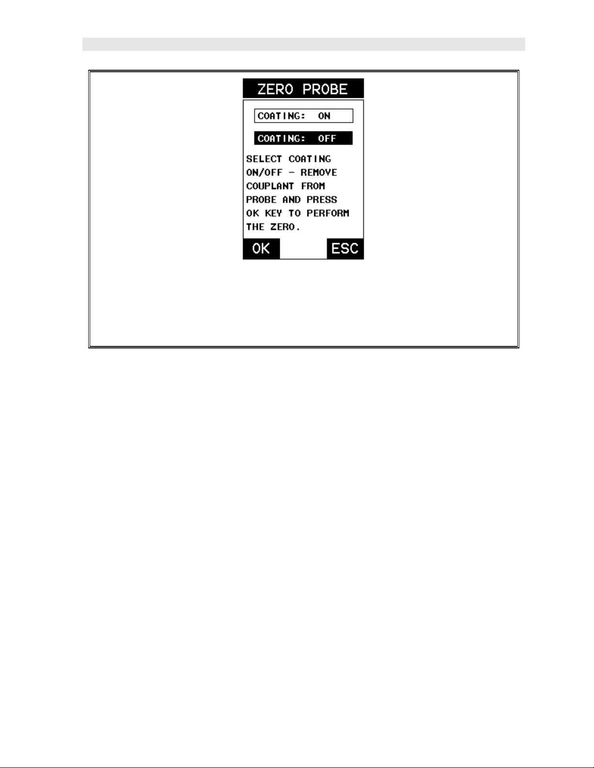
3) Press the UP and DOWN arrow keys to toggle the coating option on/off.
4) Wipe all couplant from the transducer face and advance to the Probe Zero
& Calibration section outlined below.
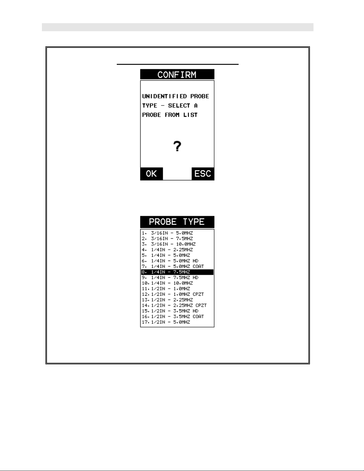
2.3 Selecting the Transducer Type
If the CMXDL does not identify a specific transducer type on initial power up, the user
will be required to select a type from a predefined list of types by diameter and
frequency. By selectin g a transducer type from a predefined list, the CMXDL can
recall specific properties about the transducer. Note: Once the transducer has been
selected, the CMXDL will store and recall this transducer type every time the CMXDL is
powered on/off. The type will only change if the user physically selects another
transducer type from the list, or selects a previously saved setup. However, the
CMXDL will continue to take you through these steps each time the gauge is powered
up. You’ll notice that the probe type previously selected will be highlighted every time
the probe type screen is displayed. Use the following steps to select your transducer
type:
5
Page 10
Dakota Ultrasonics
Selecting the Transducer Type
1) Press the OK or ESC keys to display the factory list of transducer types (by
diameter and frequency).
2) Press the UP and DOWN arrow keys to scroll through the transducer list
until the appropriate type is highlighted.
6
Page 11
CMX DL High Performance Material & Coating Thickness Gauge
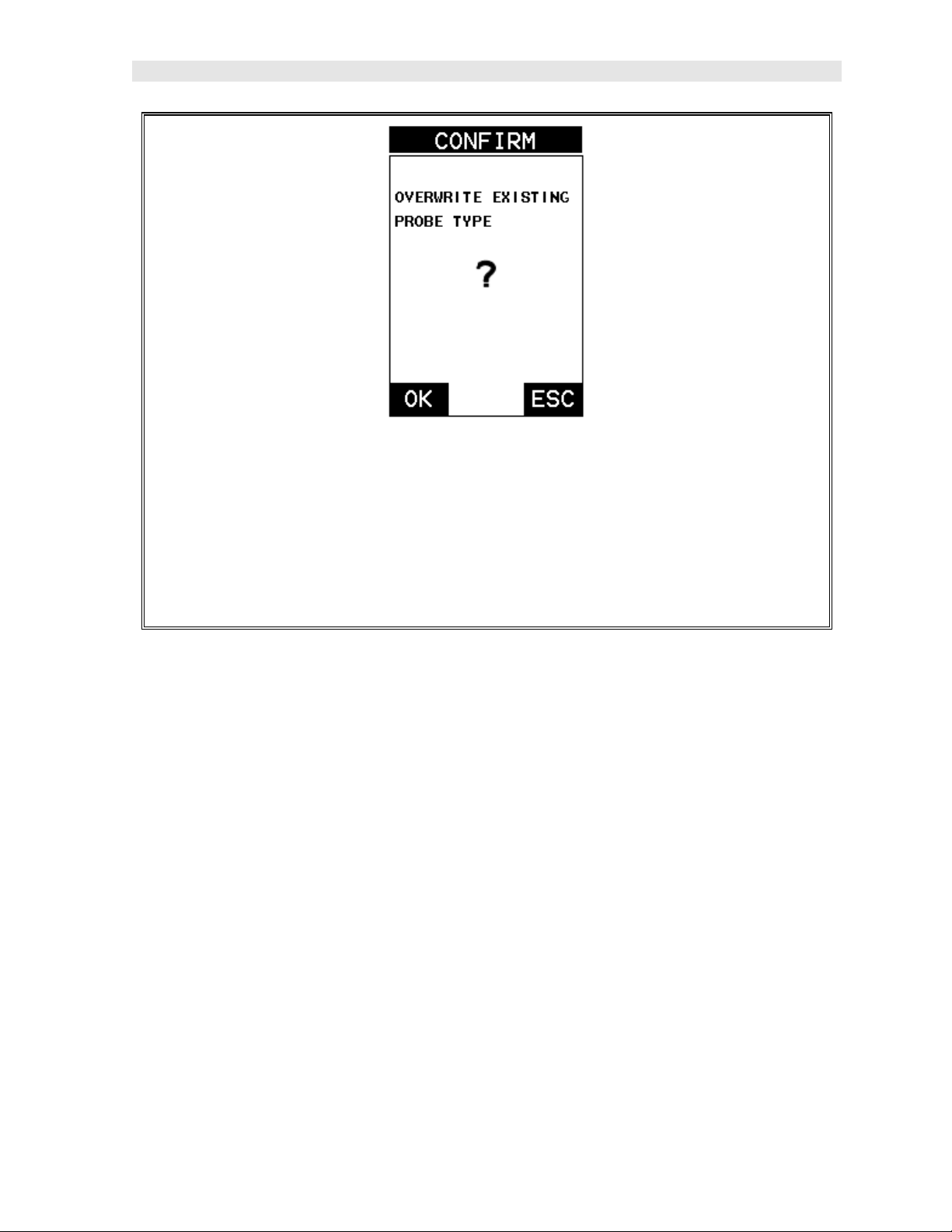
3) Press the ENTER key to select the transducer type and display overwrite
existing probe screen.
4) Press the OK key to overwrite the existing probe type with the newly
selected probe type. The zero probe screen will be displayed. Proceed to
the zero probe section that follows.
2.4 Probe Zero & Calibration
The next steps are to perform a probe zero and calibrate the CMXDL to the material
and transducer being used. If the sound velocity is unknown, the CMXDL can be
calibrated to a known thickness sample. This demo will briefly explain both of these
techniques.
The CMXDL is equipped with two zero options:
1) Off Block Zero (Automatic Probe Zero) – When this feature is enabled the
CMXDL will do an electronic zero automatically, eliminating the need for a zero
disk or block.
2) On Block Zero (Manual Probe Zero) – When this feature is enabled the
transducer must be placed on the probe zero disk (battery cover located on the
top of the unit.
Note: Transducers of the same type will have very slight mechanical and electrical
variations. If it’s discovered that the linearity is off following an initial auto probe zero
and extreme accuracy is required, a manual zero should be performed followed by an
auto zero. This will adjust and eliminate any error. This is only required if it’s
discovered the transducer is non-linear following an initial auto probe zero.
The procedures are outl ined as follows:
7
Page 12
Dakota Ultrasonics
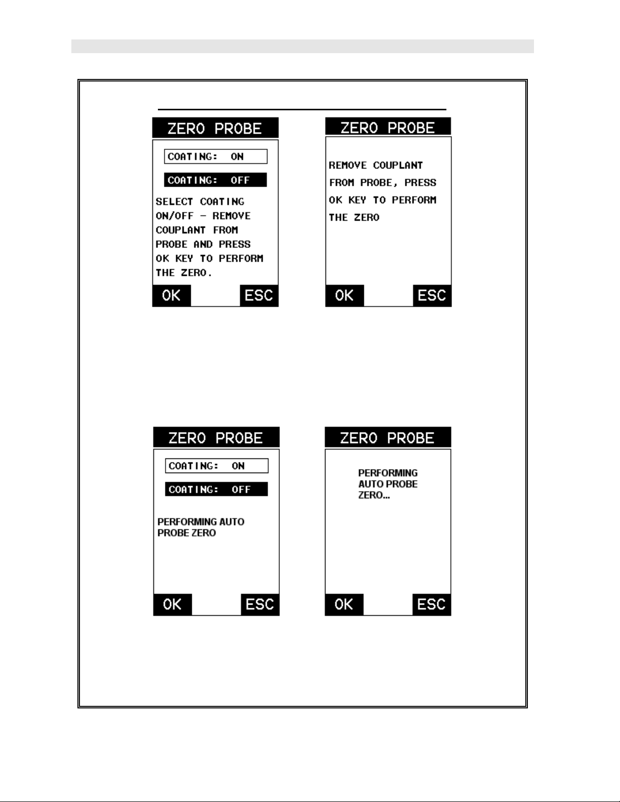
Performing an Auto Probe Zero (Off Block)
Coating Probe Identified Coating Probe Not Identified
1) Be sure all couplant has been removed from the face of the transducer.
2) Press the OK key to perform the automatic probe zero, or ESC key to
cancel the zero operation.
Coating Probe Identified Coating Probe Not Identified
3) The screens illustrated above will be briefly displayed followed by the main
measurement screen. The CMXDL is ready to be calibrated.
8
Page 13
CMX DL High Performance Material & Coating Thickness Gauge
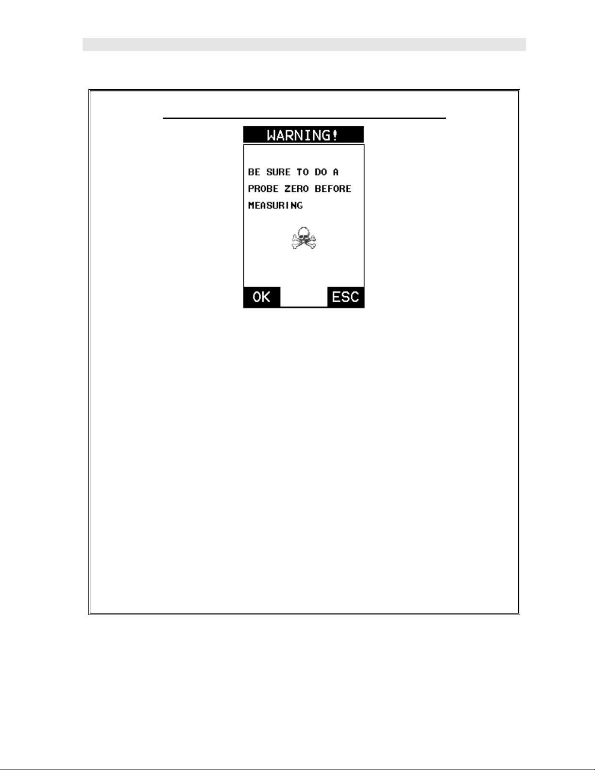
Performing a Manual Probe Zero (On Block)
Note: When the zero probe option is set to manual, the probe zero disk
(battery cap) located on the top of the gauge, will be used as a zero standard
and the warning screen illustrated above will be displayed.
1) Press the OK or ESC keys to enter the main measurement screen and
begin the manual zero process.
2) Apply a drop of couplant on the transducer and place the transducer in
steady contact with the probe zero disk, and obtain a steady reading.
3) Press the MENU key once to activate the menu items tab. Press the MENU
key multiple times to tab right and the ESC key multiple times to tab left until
the PRB menu is highlighted and displaying the submenu items.
4) Press the UP and DOWN arrow keys to scroll through the sub menu items
until ZERO PROBE is highlighted.
9
Page 14
Dakota Ultrasonics
Coating Probe Identified Coating Probe Not Identified
5) Press the ENTER key to display the confirmation screen.
6) If a coating transducer was identified use the UP and DOWN arrow keys to
toggle coating on/off.
7) Press the OK key to complete the probe zero function, or ESC key to cancel
the probe zero function.
8) Remove the transducer from the probe zero disk, and proceed to the
calibration section.
Note: The value that is displayed will change depending on the current velocity
setting in the CMXDL. Disregard the number that is displayed. It is not
important. What is important is accurately performing the steps outlined above
to insure reliability of the probe zero calculation.
One Point Material Calibration
For the purposes of this quick start section, we’ll only be covering the most common
one point calibration option to determine the sound velocity of the test material. It
would be very handy to carry a set of mechanical calipers to use in conjunction with
the CMXDL for calibration in the field:
10
Page 15
CMX DL High Performance Material & Coating Thickness Gauge
Using a Known Thickness
Note: Be sure that the probe zero procedure has been performed prior to
performing this calibration procedure.
1) Physically measure an exact sample of the material or a location directly on
the material to be measured using a set of calipers or a digital micrometer.
2) Apply a drop of couplant on the transducer and place the transducer in
steady contact with the sample or actual test material. Be sure that the
reading is stable and the repeatability indicator, in the top left corner of the
display, is fully lit and stable. Press the MENU key once to activate the
menu items tab. Press the MENU key multiple times to tab right and the
ESC key multiple times to tab left until the CAL menu is highlighted and
displaying the submenu items.
3) Use the UP and DOWN arrow keys to scroll through the sub menu items
until MATL 1PT is highlighted.
11
Page 16
Dakota Ultrasonics
4) Press the ENTER key to display the Digits Edit Box.
5) Press the UP and DOWN arrow keys to scroll the highlighted value.
6) Press the LEFT and RIGHT arrow keys to scroll the digit locations.
7) Repeat steps 5 & 6 until the known thickness value is correctly displayed.
8) Press the OK key to calculate the velocity and return to the menu screen, or
ESC to cancel the one point calibration.
9) Finally, press the MEAS key to return to the measurement screen and begin
taking readings.
Note: CHECK YOUR CALIBRATION! Place the transducer back on the
calibration point. The thickness reading should now match the known
thickness. If the thickness is not correct, repeat the steps above.
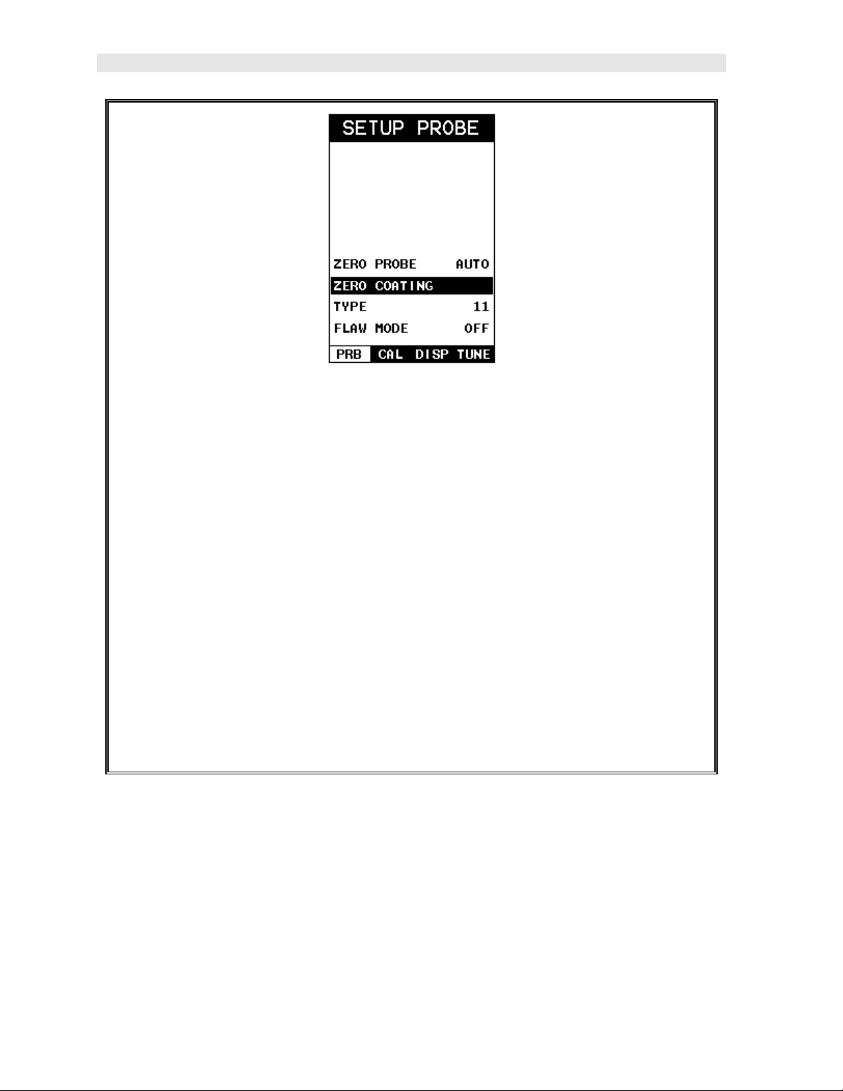
2.5 Zero Coating
In order to account for very slight electronic differences in transducers of the same
type, frequency, and diameter, the CMXDL has been equipped with a “zero coating”
feature. This enables the CMXDL to obtain very accurate readings on coatings,
eliminating potential errors incurred from slight differences in the manufacturing
processes. The procedure is outlined below:
12
Page 17
CMX DL High Performance Material & Coating Thickness Gauge
Performing a Coating Zero
1) Press the MULTI MODE key once to activate the measurement mode
options.
2) Use the UP and DOWN arrow keys to scroll through the sub menu items
until Coating Only (CT) mode is highlighted.
3) Press the ENTER key to select the measurement mode and return to the
measurement screen.
4) Apply a drop of couplant on the transducer and place the transducer in
steady contact with the probe zero disk (battery cover) and obtain a steady
reading.
Note: The coating measurement displayed will potentially be a value greater or
less than 0.
5) Press the MENU key once to activate the menu items tab. Press the MENU
key multiple times to tab right and the ESC key multiple times to tab left until
the PRB menu is highlighted and displaying the submenu items.
13
Page 18
Dakota Ultrasonics
6) Use the UP and DOWN arrow keys to scroll through the sub menu items
until ZERO COATING is highlighted.
7) Press the ENTER key to display the confirmation screen.
8) Press the OK key to zero the coating and return to the PRB menu, or ESC
to cancel the coating zero process.
9) Press the MULTI MODE key once to activate the measurement mode
options.
10) Use the UP and DOWN arrow keys to scroll through the sub menu items
until Coating On (PECT) is highlighted.
11) Press the ENTER key to select the measurement mode and return to the
measurement screen, and begin taking readings.
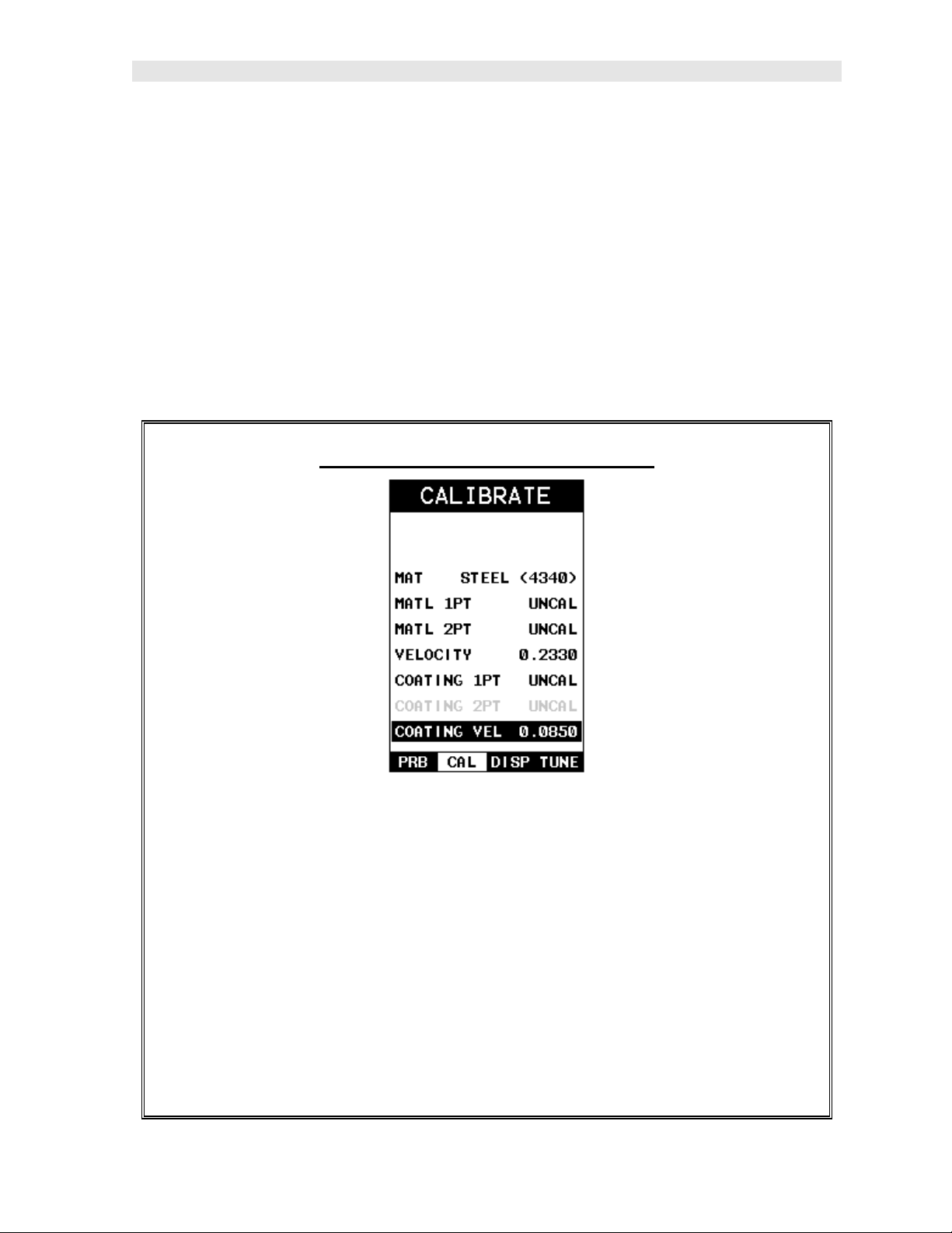
2.6 Coating Calibration
The CMXDL has been preset to a default coating velocity of 0.0850 in/µsec (2159
m/sec). This will be very close to the most common coating material velocities used
in the field. If the velocity of the coating is known, and different than the above
default setting, the user can simply enter the coating velocity into the CMXDL.
However, if the velocity is unknown, the CMXDL can also be calibrated to a specific
coating sample/type using the 1pt calibration option in PECT (pulse-echo coating)
mode, or a two point calibration is CT (coating only) mode. For the purpose of this
14
Page 19
CMX DL High Performance Material & Coating Thickness Gauge
quick start section only the 1pt option PECT (pulse-echo coating) mode will be
covered. Refer to the calibration section of the manual for a complete explanation on
the coating calibration options. The following steps below outline the necessary
steps to either set the velocity of the coating, or perform a one point calibration to
calculate the coating velocity:
Known Coating Velocity
If the coating velocity is known, the user may wish to simply enter the velocity
number into the CMXDL, rather than have the CMXDL calculate the velocity value
using a known thickness on a coating sample. The steps for entering the velocity are
outlined below:
Using a Known Coating Velocity
12) Press the MENU key once to activate the menu items tab. Press the MENU
key multiple times to tab right and the ESC key multiple times to tab left until
the CAL menu is highlighted and displaying the submenu items.
13) Use the UP and DOWN arrow key s to scroll through the sub menu items
until COATING VEL is highlighted.
14) Press the ENTER key to display the Digits Edit Box.
15) Press the UP and DOWN arrow keys to scroll the highlighted value.
16) Press the LEFT and RIGHT arrow keys to scroll the digit locations.
15
Page 20
Dakota Ultrasonics
17) Repeat steps 4 & 5 until the velocity number is correctly displayed.
18) Press the OK key to set the coating velocity and return to the menu screen,
or ESC to cancel entering the coating velocity.
19) Finally, press the MEAS key to return to the measurement screen and
begin taking readings.
Known Coating Thickness
When the exact velocity of a coating is unknown, the user has the option of
performing a one point calibration on a sample of the coating with a known thickness
to determine the sound velocity. It would be very handy to carry a set of mechanical
calipers to use in conjunction with the CMXDL for calibration in the field:
Using a Coating Sample to Calibrate
1) Physically measure a location on a coating sample using a set of calipers or
a digital micrometer.
16
Page 21
CMX DL High Performance Material & Coating Thickness Gauge
Important Note: In PECT (pulse-echo coating) mode, the coating sample must
be coupled to metal in order to calibrate successfully. Simply place a drop of
couplant on a piece of metal, lay the coating sample over the couplant on the
metal and proceed to step 2.
2) Apply a drop of couplant on the transducer and place the transducer in
steady contact with the coating (on metal) sample or actual test material. Be
sure that the reading is stable and the repeatability indicator, in the top left
corner of the display, is fully lit and stable. Press the MENU key once to
activate the menu items tab. Press the MENU key multiple times to tab right
and the ESC key multiple times to tab left until the CAL menu is highlighted
and displaying the submenu items.
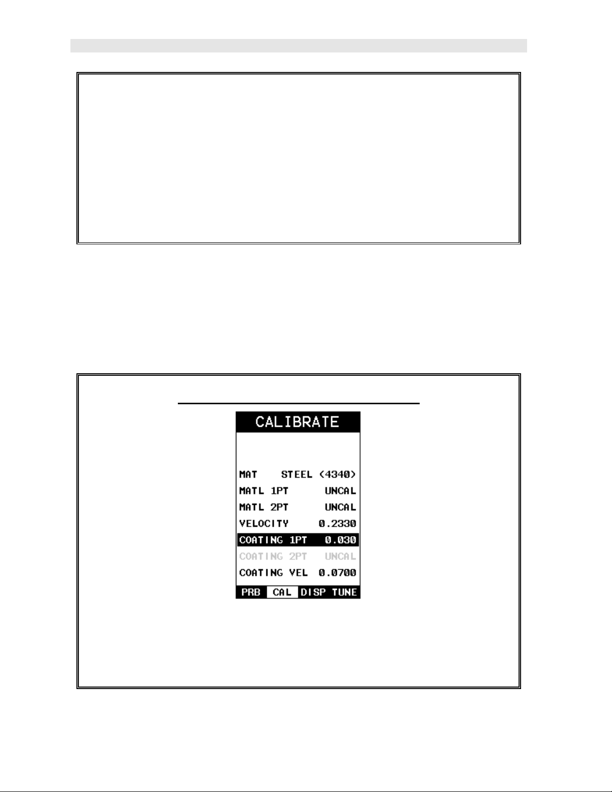
3) Use the UP and DOWN arrow keys to scroll through the sub menu items
until COATING 1PT is highlighted.
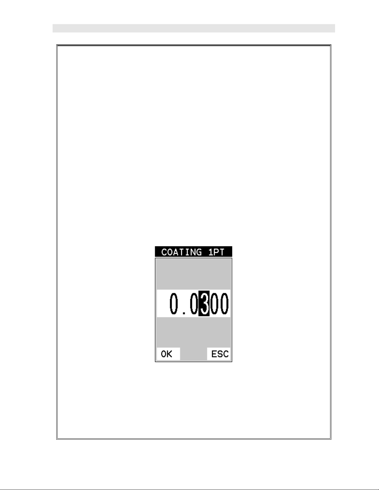
4) Press the ENTER key to display the Digits Edit Box.
5) Press the UP and DOWN arrow keys to scroll the highlighted value.
6) Press the LEFT and RIGHT arrow keys to scroll the digit locations.
7) Repeat steps 5 & 6 until the known thickness value is correctly displayed.
17
Page 22
Dakota Ultrasonics
8) Press the OK key to calculate the coating velocity and return to the menu
screen, or ESC to cancel the one point calibration.
9) Finally, press the MEAS key to return to the measurement screen and begin
taking readings.
Note: CHECK YOUR CALIBRATION! Place the transducer back on the
calibration point. The coating thickness reading should now match the known
coating thickness sample. If the thickness is not correct, repeat the steps
above.
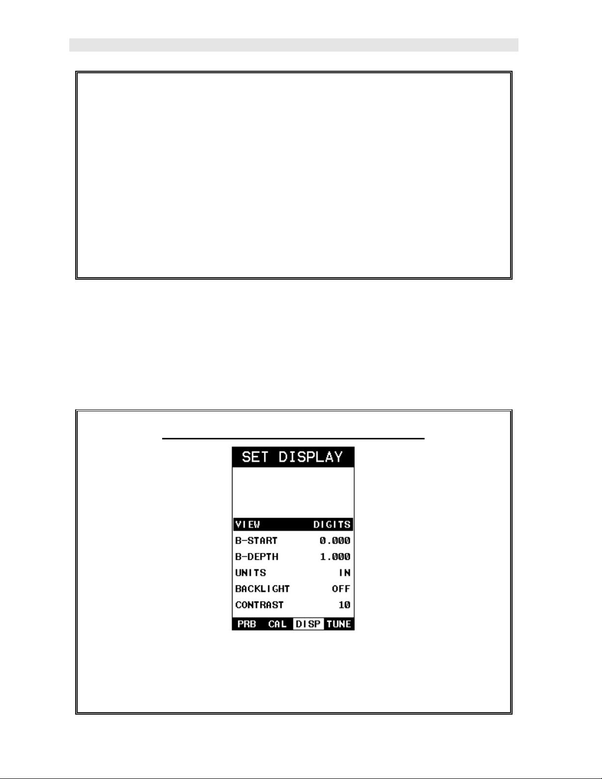
2.7 Measure
The CMXDL is now ready to measure. There are two different measurement view
options, each with a specific purpose – Digits & B-Scan. The steps below outline
how to toggle between the different view mode options:
Selecting the Measurement View Option
1) Press the MENU key once to activate the menu items tab. Press the MENU
key multiple times to tab right and the ESC key multiple times to tab left until
the DISP menu is highlighted and displaying the submenu items.
18
Page 23
CMX DL High Performance Material & Coating Thickness Gauge
2) Use the UP and DOWN arrow keys to scroll through the sub menu items
until VIEW is highlighted.
3) Use the LEFT and RIGHT arrow keys to scroll the view options.
4) Once the view is displayed, press the MEAS key to return to measurement
mode.
DIGITS: Displays the digital thickness value using a large font size. This view is
useful when the CMXDL is being used as a basic thickness gauge.
BSCAN: The Time Based B-Scan provides the user with a cross sectional view of
the material being tested. This mode is useful when there is concern regarding the
profile of the blind surface. This can also be a useful view when scanning for pits and
flaws.
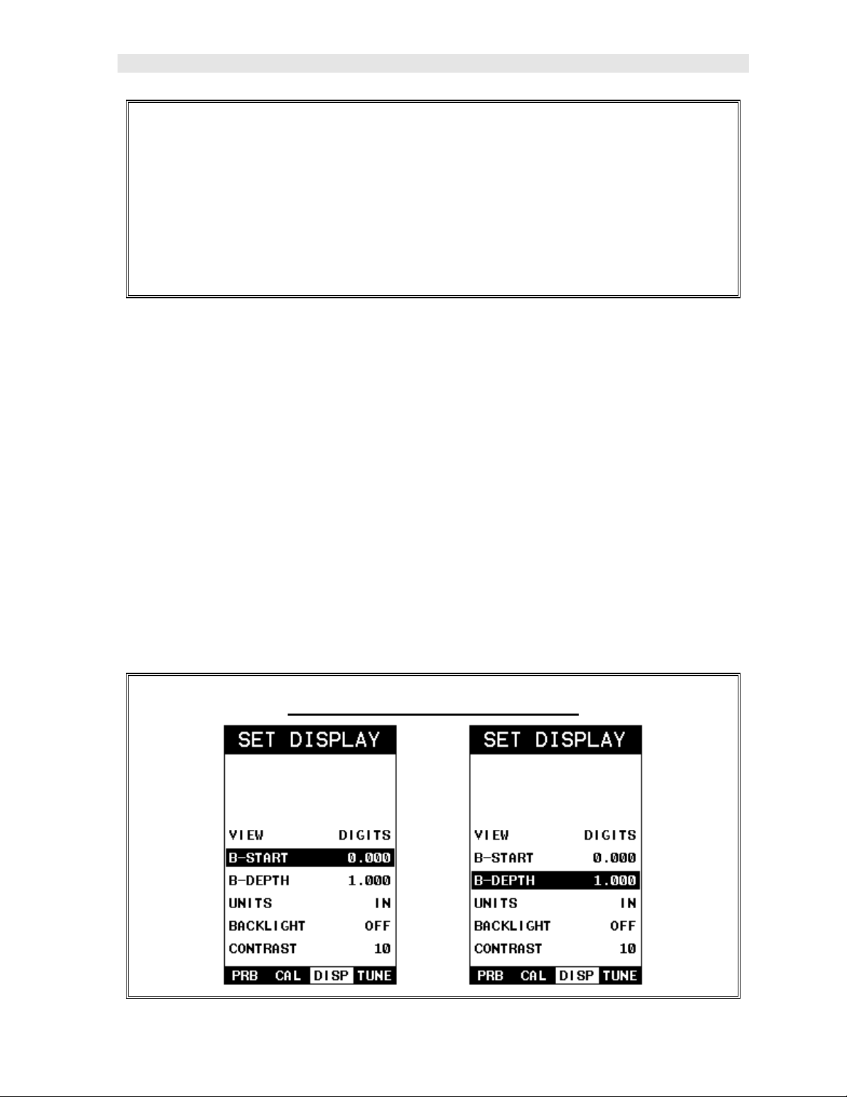
Once the view has been selected according to the application requirements, the B-
START and B-DEPTH of the screen will potentially need to be adjusted if the view
has been set to BSCAN. Use the following steps to adjust these as follows:
Note: The B-Start and B-Depth are also used to adjust the parameters of Scan
Bar.
Adjusting B- START & B-DEPTH
19
Page 24
Dakota Ultrasonics
1) Press the MENU key once to activate the menu items tab. Press the MENU
key multiple times to tab right and the ESC key multiple times to tab left until
the DISP menu is highlighted and displaying the submenu items.
2) Use the UP and DOWN arrow keys to scroll through the sub menu items
until B-START or B-DEPTH is highlighted.
3) Use the LEFT or RIGHT arrow keys to increase/decrease the start or depth
values in coarse increments/decrements.
4) Repeat steps 2 & 3 until the range is correctly being displayed.
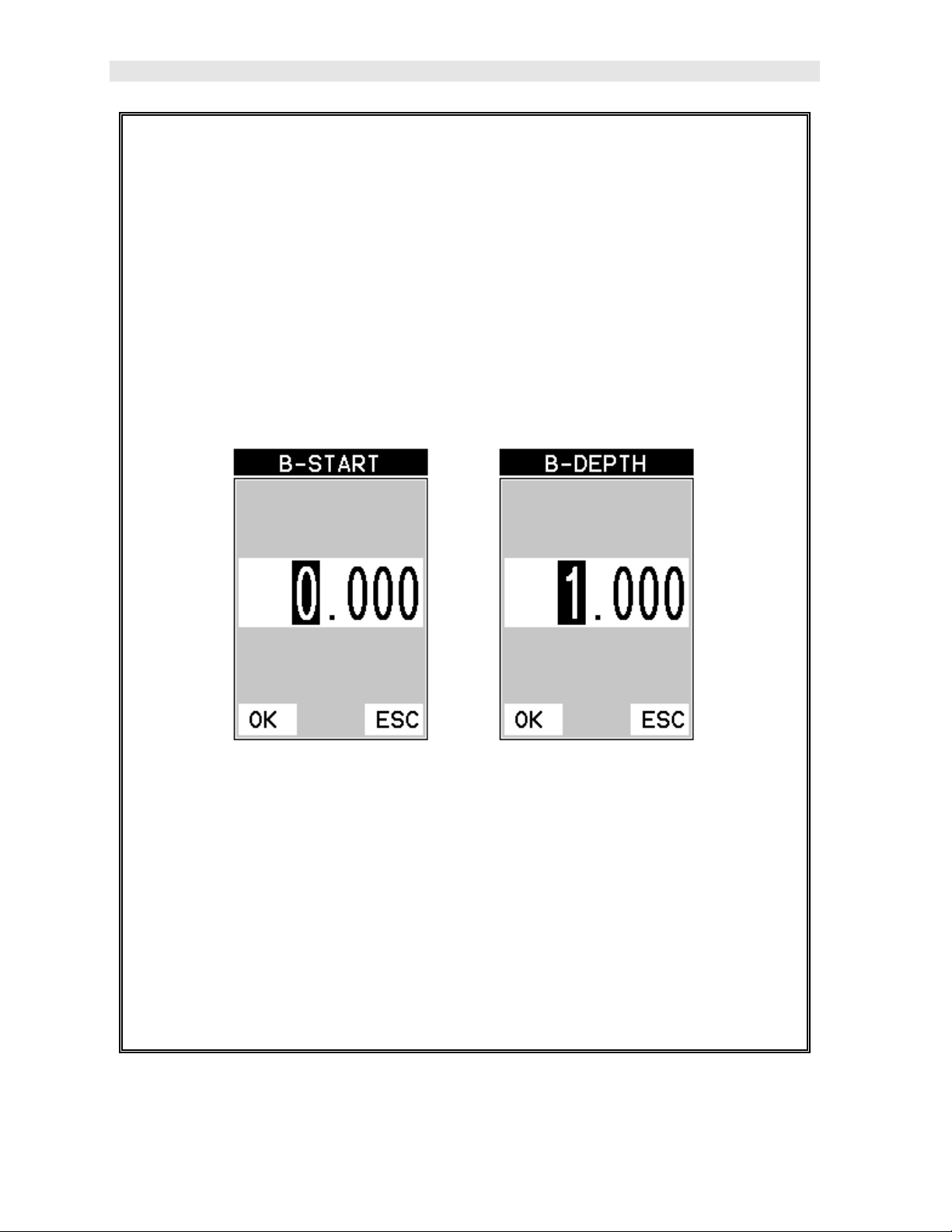
Alternatively, the B-START and B-DEPTH values can be changed using the
Digit Edit Box as follows:
1) Use the UP and DOWN arrow keys to scroll through the sub menu items
until B-START or B-DEPTH is highlighted.
2) Press the ENTER key to display the digits edit box.
3) Press the UP and DOWN arrow keys to scroll the highlighted value.
4) Press the LEFT and RIGHT arrow keys to scroll the digit locations.
20
Page 25
CMX DL High Performance Material & Coating Thickness Gauge
5) Repeat steps 3 & 4 until the B-START or B-DEPTH value is correctly
displayed.
6) Press the OK key to set the B-START or B-DEPTH value and return to the
DISP menu , or ESC to cancel entering the B-START or B-DEPTH value.
Note: the adjusted value will appear next to the B-START or B-DEPTH
menu labels.
7) Finally, press the MEAS key to return to the measurement screen and begin
taking readings.
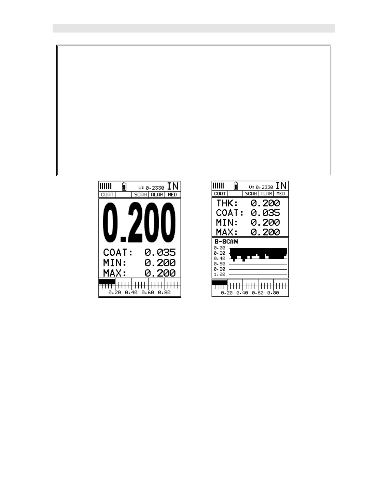
DIGITS B-SCAN
In the upper left corner of each of the display photos above, is the repeatability
indicator. The repeatability indicator is represented by five vertical bars and
represents how repeatable the measurements are. In regular measurement mode,
the CMXDL makes 8 measurements a second. In scan mode, the CMXDL makes 200
measurements a second. If the coating mode option is activated, the CMXDL makes
3 measurements a second in regular measurement mode and 65 measurements a
second in scan mode. When the CMXDL is idle, only the left vertical bar will be
displayed. However, when the CMXDL is making a measurement, four or five of the
bars should be displayed on the repeatability indicator. If f ewer than four bars are
showing, the CMXDL is having difficulty achieving a stable measurement and the
thickness value displayed is potentially unstable.
21
Page 26
CHAPTER THREE
KEYBOARD, MENU, & CONNECTOR REFERENCE
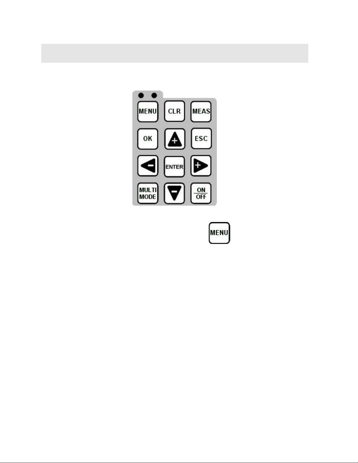
3.1 Menu Key (Operation & Sub Menus)
The Menu key activates the primary menu structure containing 8 menu tab groups.
These tab groups then contain sub menu items, or functions. The sub menu items
have been organized in tab groups according to how closely they are related to the
individual tab group names. L et’s first get familiar with how to move around in these
tabs before continuing on to the sub menu functions. This procedure is outlined
below:
22
Page 27
CMX DL High Performance Material & Coating Thickness Gauge
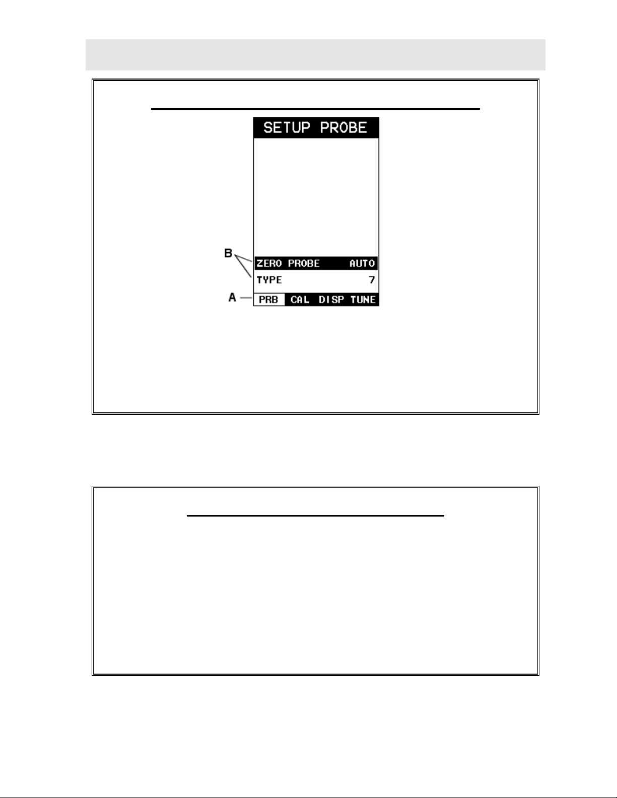
Activating and Getting Around in the Menu Items
1) Press the MENU key once to activate the menu items tab. Pr ess the MENU
key multiple times to tab right, and the ESC key multiple times to tab left
until the desired tab group is highlighted and displaying the submenu items.
The tab groups are illustrated above (A).
Now that you’re familiar with activating and moving amongst the tab groups, let’s
have a look at how to move around in the sub menu items as follows:
Getting Around in the Sub Menu Items
1) Use the UP and DOWN arrow keys to scroll through the sub menu items
until the desired function is highlighted. The sub menu items are illustrated
in the diagram above (B).
2) Depending on which function is highlighted, use the LEFT, RIGHT, and
Enter keys to scroll the options or activate the Digit Edit and List Box
options.
The sections to follow will provide the user with an explanation of the sub menu
functions:
23
Page 28
Dakota Ultrasonics
3.2 Probe – Menu
ZERO PROBE: The CMXDL is zeroed in much the same way that a mechanical
micrometer is zeroed. If the CMXDL is not zeroed correctly, all of the measurements
made using the CMXDL may be in error by some fixed value. The CMXDL is equipped
with an optional automatic or manual zero feature. Refer to the section on page 43,
for an explanation of this important procedure.
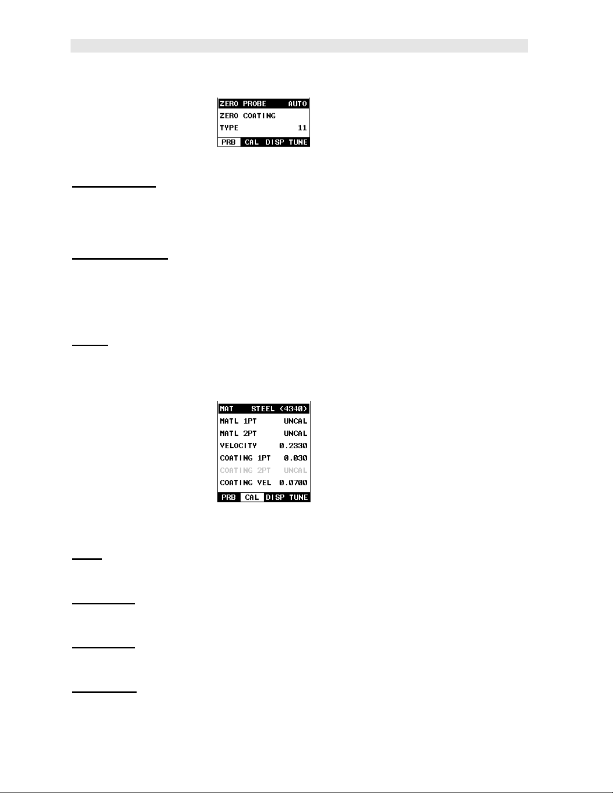
ZERO COATING: In order to account for very slight electronic differences in
transducers of the same type, frequency, and diameter, the CMXDL has been
equipped with a “zero coating” feature. This enables the CMXDL to obtain very
accurate readings on coatings, eliminating potential errors incurred from slight
differences in the manufacturing processes. Refer to the section on page 43, for a
detailed explanation.
TYPE: Enables the user to select the type of transducer being used from a chart of
transducer types. This provides increased linearity between transducers. Refer to
page 39 for a further explanation.
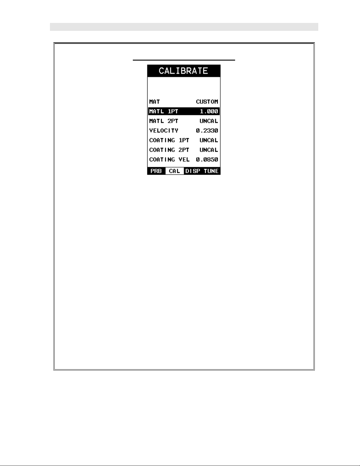
3.3 CAL – Menu
MAT: Select the material velocity from a chart of basic material types when a known
sample thickness, or material velocity cannot be obtained. Refer to page 52 for
further info.
MATL 1PT: Performs a single point calibration. This option allows the user to
automatically calculate the velocity by entering a known sample thickness. Refer to
page 49 for further info.
MATL 2PT: Performs a two-point calibration. This option allows the user to
automatically calculate the velocity by entering a second known sample thickness.
Refer to page 51 for further info.
VELOCITY: Function to calibrate the CMXDL by setting the velocity to a known
material velocity. Refer to page 46 for further info.
24
Page 29
CMX DL High Performance Material & Coating Thickness Gauge
COATING 1PT: Performs a single point coating calibrat ion. This option allows the
user to automatically calculate the velocity by measuring a known coating sample
thickness. Refer to page 77 for further info.
COATING 2PT: Performs a two-point coating calibration. This option allows the
user to automatically calculate the velocity by entering a second known coating
sample thickness. Refer to page 77 for further info.
COATING VEL: F unction to calibrate the CMXDL to a specific coating material type
by entering a coating velocity. Refer to page 15 or page 71 for further info.
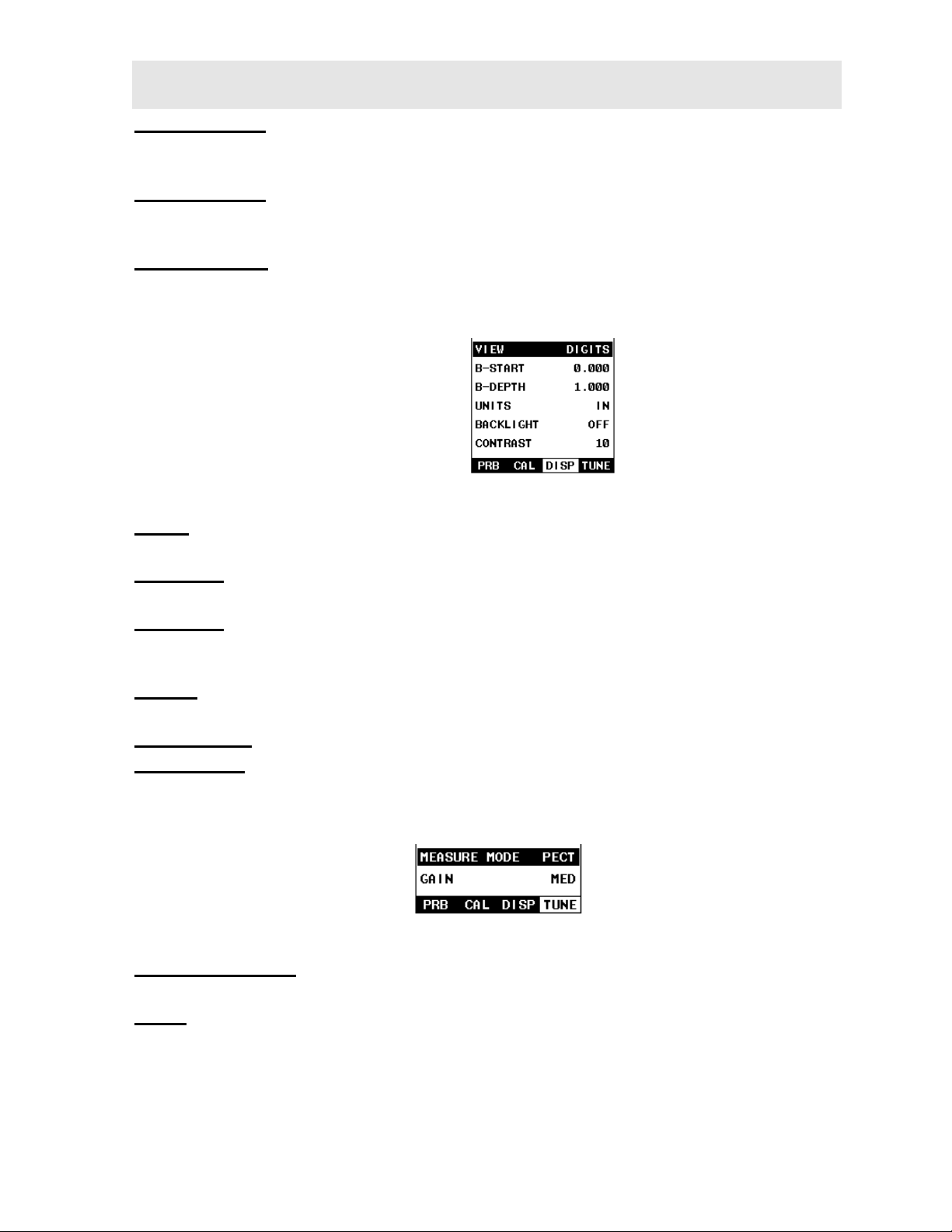
3.4 DISP (display) – Menu
VIEW: Selectable BSCAN (cross section), and DIGITS (large digits) views. Refer to
page 56 for further info.
B-START: Provides the user the ability to change the start position of the B-SCAN
view. Refer to page 60 for further info.
B-DEPTH: Provides the user the ability to change the overall depth of the viewable
measurement area. It functions a lot like a zoom on a camera. Refer to page 62 for
further info.
UNITS: Toggle between English or Metric units. The readout will change from
inches to millimeters.
BACKLIGHT: Selectable OFF, ON, AUTO, or INVERT backlight option.
CONTRAST: Adjustable display contrast for variable light conditions.
3.5 TUNE – Menu
MEASURE MODE: Toggles a variety of unique measurement modes for different
application requirements. Refer to page 32 for further info.
GAIN: A 5 position gain switch in 2 db increments from 40 to 50 dB. Increase for
better penetration or punch, and decrease to eliminate unwanted noise or better
resolution. Refer to page 64 for further info.
25
Page 30
Dakota Ultrasonics
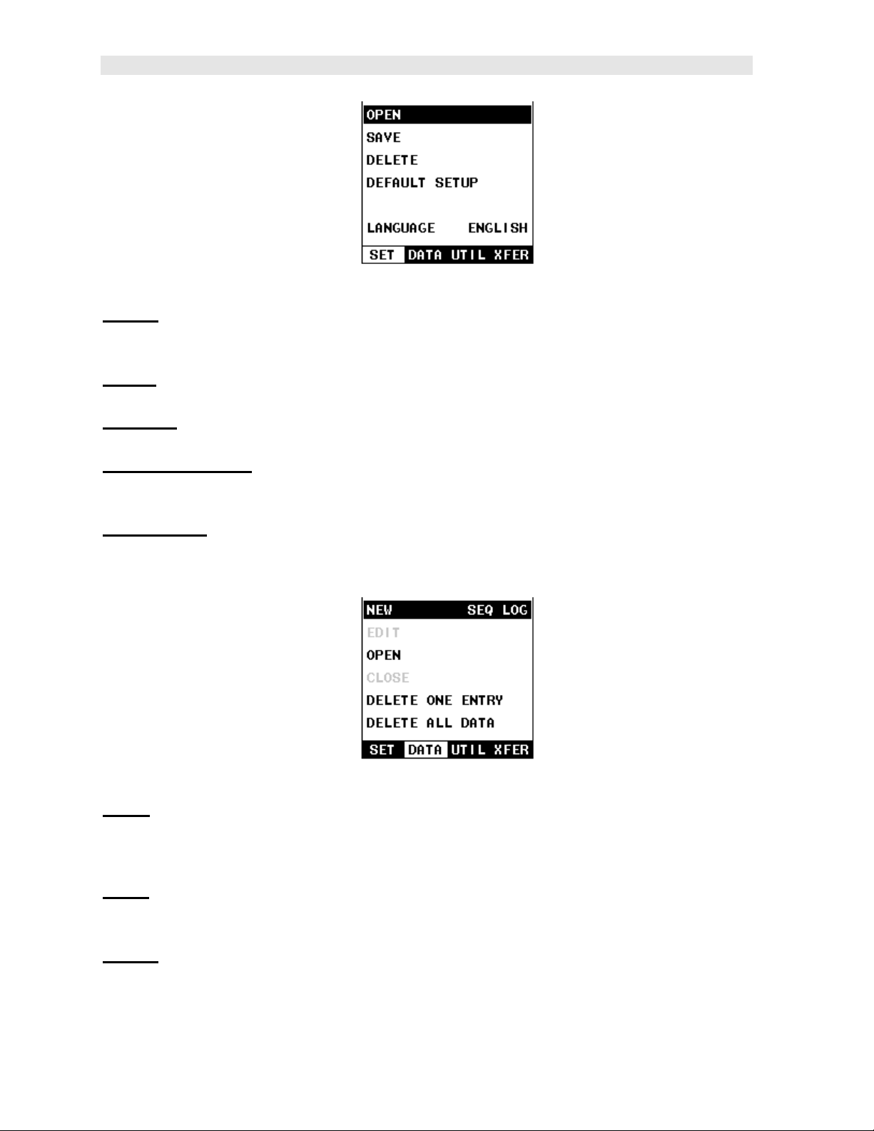
3.6 SETUP – Menu
OPEN: Displays a list of factory and user defined setups currently stored in memory.
These setups can be recalled and used at any time. Refer to page 112 for further
info.
SAVE: Provides the user with the ability to save a custom setup that has been
modified or created by the user. Refer to page 114 for further info.
DELETE: Provides the user with the ability to delete specific setups previously save
in memory. Refer to page 118 for further info.
DEFAULT SETUP : Loads a basic default setup. Use only as a last resort when the
setups in the CMXDL have been corrupted and a computer is not accessible. Refer to
page 119 for further info.
LANGUAGE: Provides the user the ability to select different languages for the
CMXDL. Refer to page 121 for further info.
3.7 DATA – Menu
NEW: Allows the user the ability to creat e a new alpha numeric grid, or sequential
log file with auto identifiers. Equipped with custom parameters, rows, and columns
depending on the users application reporting requirements. Refer to page 88 for
further info.
EDIT: Giv es the user the ability to change parameters of grid or sequential file
previously saved. Note: Pre-defined coordinates cannot be changed once they have
been created. Refer to page 105 for further info.
OPEN: This function provides the user with the ability to recall grids or sequential log
files that currently exist in memory, from a list of grids. Refer to page 108 for further
info.
26
Page 31

CMX DL High Performance Material & Coating Thickness Gauge
CLOSE: Provides the user the ability to close a currently opened grid or sequential
log file. Refer to page 110 for further info.
DELETE ONE FILE: This function provides the user with the ability to delete one
individual grid or sequential log file from a list of multiple grids/files previously saved
in memory. Refer to page 103 for further info.
DELETE ALL DATA : This function provides the user with the ability to delete all files
currently stored in memory. Refer to page 104 for further info.
3.8 UTIL (utilities) – Menu
SCAN MODE: This function enables a hi speed scan mode that increases the
overall sample rate from 65 to 200 measurements per second, depending on the
current measurement mode used. Refer to page 82 for further info.
ALARM: Toggles alarm mode on , off, or audible. Refer to page 83 for further info.
ALARM HIGH: Gives the user the ability to set the HI limit parameter. If the
measurement exceeds this value, a red light will illuminate and sound the internal
beeper. Refer to page 83 for further info.
ALARM LOW : Gives the user the ability to set the LO limit parameter. If the
measurement falls below this value, a red light will illuminate and sound the internal
beeper. Refer to page 83 for further info.
DIFFERENTIAL: Gives the user the ability to set a nominal value and the CMXDL will
display +/- the difference from the nominal value entered. Refer to page 85 for
further info.
3.9 XFER (transfer) – Menu
BACKUP SETUPS : Enables the user the ability to backup the setups currently
stored in the CMXDL to a PC via RS232 port. Refer the help section of the CMX
DakView software for a complete electronic manual.
DL
27
Page 32

Dakota Ultrasonics
RESTORE SETUPS : Enables the user the ability to restore the setups currently
saved on a PC to an CMXDL via RS232 port. Refer the help section of the CMXDL
DakView software for a complete electronic manual.
BACKUP DATA : Enables the user the ability to backup grids or sequential log files
currently stored in the CMXDL to a PC via RS232 port. Refer the help section of the
DL
CMX
RESTORE DATA : Enables the user the ability to restore grids or sequential log files
currently saved on a PC to an CMXDL via RS232 port. Refer the help section of the
CMXDL DakView software for a complete electronic manual.
ABOUT: Provides the user with Dakota Ultrasonics con tact information and the
CMXDL software version. Refer the Dakota Ultrasonics web site for information on
the latest firmware versions available for download.
DakView software for a complete electronic manual.
3.10 CLR (clear) Key
The primary functions of the CLR key, is to clear a measurement from a grid or
sequential log files cell location or set obstruct, and backspace in an Alpha Edit Box.
If a user has already saved a measurement and B-Scan to a cell location, use this
key to clear the measurement at any time.
3.11 MEAS (measurement mode) Key
The MEAS key puts the CMXDL into it’s primary mode of operation. In this mode, the
user has a complete view of the LCD.
3.12 OK Key
The primary function of the OK key is confirmation of a change or selection. If the
CMXDL is displaying a grid log, the OK key toggles an advance to row number option.
3.13 ESC Key
The ESC key is used in the MENU, MEAS, and EDIT functions as a back or escape
function. If the CMX
display options: Digits and B-Scan views.
DL+
is displaying a grid or sequential log, the OK key toggles the
28
Page 33

CMX DL High Performance Material & Coating Thickness Gauge
3.14 Arrow Keys
The Arrow Keys are used to navigate through the menus, increase/decrease values,
and toggle specific function keys.
3.15 ENTER key
The ENTER key is used in the overall menu selection process, to activate list and
edit boxes, display and save measurements to grid or sequential files locations. Use
this key to open your log files while making measurements.
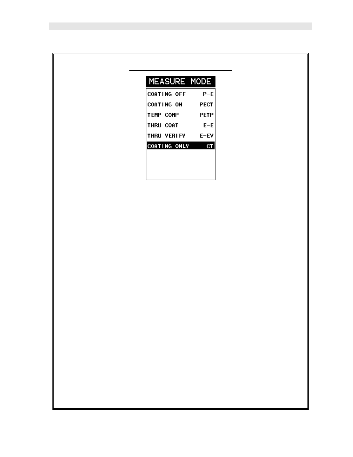
3.16 MULTI MODE Key
The MULTI MODE key opens a measurement mode screen listing all the modes that
are available to the transducer specifically selected. The modes can be all or a
combination of the entire set of modes the CMXDL offers, depending on which
transducer is being used as follows: Coating Off (P-E), Coating On (PECT), Temp
Comp (PETP), Thru-Coat (E-E), Thru Coat Verify (E-EV), and Coating Only (CT).
3.17 ON/OFF Key
The ON/OFF key simply powers the unit either ON or OFF. Note: Unit will
automatically power off when idle for 5 minutes. All current settings are automatically
saved prior to powering off.
29
Page 34

3.18 Top & Bottom End Caps
The top & bottom end panels are where all connections are made to the CMXDL. The
diagram above shows the layout and description of the connectors:
Transducer Connectors
Refer to Diagram: The transducer connectors, and battery cover/probe zero disk are
located on the CMXDL’s top end cap. The transducer connectors are of type Lemo
“00”. Note: There is no polarity associated with connecting the transducer to the
CMXDL.
Probe Zero Disk & Battery Cover
Refer to Diagram: The Battery cover is the large round disk shown in the diagram.
Note: This same disk is also used as a probe zero disk. Simply remove the cover
when replacing the batteries (3 AA cells). When performing a manual probe zero
function, simply place the transducer on disk making firm cont act. Important: Be
sure to follow the polarity labels located on the back label of the CMXDL. Note:
Rechargeable batteries can be used, however they must be recharged outside of the
unit in a stand alone battery charger.
RS-232 Connector
Refer to Diagram: The RS-232 connector, located on the bottom end cap, is a 2 pin
female Lemo connector. It is designed to connect directly from the CMXDL to a
standard AT serial port on a PC. The cable supplied with the CMXDL is a Lemo to 9
pin serial cable. Note: This connector is also used to upgrade the CMXDL with the
latest version of firmware.
USB Serial to USB Converter Cable
A converter cable can be attached to the 9 pin serial cable in needed (part no. N -402-
0510).
30
Page 35

CHAPTER FOUR
PRINCIPALS OF ULTRASONIC MEASUREMENT
4.1 Time versus thickness relationship
Ultrasonic thickness measurements depend on measuring the length of time it takes
for sound to travel through the material being tested. The ratio of the thickness
versus the time is known as the sound velocity. In order to make accurate
measurements, a sound velocity must be determined and entered into the
instrument.
The accuracy of a thickness measurement therefore depends on having a consistent
sound velocity. Some materials are not as consistent as others and accuracy will be
marginal. For example, some cast materials are very granular and porous and as a
result have inconsistent sound velocities.
While there are many different ultrasonic techniques to measure thickness, which will
be discussed below, all of them rely on using the sound velocity to convert from time
to thickness.
4.2 Suitability of materials
Ultrasonic thickness measurements rely on passing a sound wave through the
material being measured. Not all materials are good at transmitting sound.
Ultrasonic th ickness measurement is practical in a wide variety of materials including
metals, plastics, and glass. Materials that are difficult include some cast materials,
concrete, wood, fiberglass, and some rubber.
4.3 Range of measurement and accuracy
The overall measurement capabilities, based on the wide variety of materials, is
determined by the consistency of the material being measured
The range of thickness that can be measured ultrasonically depends on the material
as well as the technique being used and the type of transducer. Thickness
measurements can be made from a minimum of 0.010 inch to 9.999” in steel.
However, the maximum attainable thickness is much less for more attenuative
materials (materials that absorb sound).
Accuracy, is determined by how consistent the sound velocity is through the sound
path being measured, and is a function of the overall thickness of the material. For
example, the velocity in steel is typically within 0.5% while the velocity in cast iron
can vary by 4%.
4.4 Couplant
All ultrasonic applications require some medium to couple the sound from the
transducer to the test piece. Typically a high viscosity liquid is used as the medium.
The sound frequencies used in ultrasonic thickness measurement do not travel
31
Page 36

Dakota Ultrasonics
through air efficiently. By using a liquid couplant between the transducer and test
piece the amount of ultrasound entering the test piece is much greater.
4.5 Temperature
Temperature has an effect on sound velocity. The higher the temperature, the slower
sound travels in a material. High temperatures can also damage transducers and
present a problem for various liquid couplants.
Since the sound velocity varies with temperature it is important to calibrate at the
same temperature as the material being measured.
Normal temperature range
Most standard transducers will operate from 0°F to 180°F.
High temperature measurements
Special transducers and couplants are available for temperatures above 180°F up to
650°F with intermittent contact. It is necessary to cool the transducer, by submerging
the transducer in water between readings, when measuring high temperatures.
Modes and temperature errors
In addition to errors caused by velocity changing with temperature, some modes
(measurement techniques) are affected more than others. For example, dual
element pulse-echo mode has larger errors due to changes in the temperature of the
delay line. However, multi-echo techniques offer temperature compensation help to
minimize these errors.
4.6 Measurement Modes
In this section we will discuss the different measurements modes the CMXDL is
capable of operating in, the transducers required, and the reasons for using specific
modes:
Pulse-Echo Mode (Flaw & Pit detection) – Coating Off (P-E)
Pulse-echo mode measures from the initial pulse (sometimes referred to as an
artificial zero) to the first echo (reflection). In this mode, either an automatic or
manual zero can be performed depending on the zero probe function setting. If the
manual mode has been selected, the transducer is placed on a reference disk,
located on top of the CMXDL, and a key is pressed to establish a zero point for the
particular transducer. If the Auto Zero feature is enabled, a simple key press will
perform an electronic zero to establish the same zero point.
In this mode errors result from surface coatings and temperature variations.
Since pulse-echo only requires one reflection, it is the most sensitive mode for
measuring weak reflections (flaws) typically found when measuring heavily corroded
metals.
32
Page 37

CMX DL High Performance Material & Coating Thickness Gauge
V-Path Correction
Dual element delay line transducers have two piezoelectric elements mounted at an
angle on one end of the delay line. One element is used for transmitting sound, while
the other element only receives sound. The two elements and their delay lines are
packaged in a single housing but acoustically isolated from each other with a sound
barrier. This allows the transducer the ability to achieve very high sensitivity for
detecting small defects. Also, the surface of the test material does not have to be as
flat in order to obtain good measurements.
Dual element transducers are normally used in pulse-echo mode for finding defects,
and in echo-echo mode for through coating measurements.
Dual element delay line transducers are usable over a range of 0.025 inches to 20
inches depending on the material, frequency, and diameter.
A limitation of dual element delay-line transducers is the V shaped sound path.
Because the sound travels from one element to another, the time versus thickness
relationship is non-linear. Therefo re, a correction table in the instruments software is
used to compensate for this error.
Dual Element Transducer showing V-path of signal
Searching for small defects
Dual element delay line transducers are especially useful in searching for small
defects. In the pulse-echo mode with high amplifier gain, very small defects can be
measured. This is very useful during corrosion inspections overall. The dual element
style transducer will find wall deterioration, pits, and any porosity pockets during tank
and pipeline inspections.
Echo-Echo Mode – Thru-Paint (E-E)
The echo-echo mode measures between two reflections. This technique is
commonly used to eliminate errors from surface coatings and also to make
measurements in multiple layered materials. The disadvantage is that two echoes
are needed which requires a much stronger echo (reflection).
33
Page 38

Dakota Ultrasonics
Dual Element Transducer in Echo to Echo mode
Echo-Echo Verify Mode – Thru-Verify (E-EV)
The echo-echo verify mode measures between 3 reflections. Similar to E-E mode,
this technique is commonly used to eliminate errors from surface coatings and also to
make measurements in multiple layered materials. The primary benefit of this mode,
is that a comparison is made, between the 2nd and 3rd echoes, to verify that a peak
jump has not occurred, providing an additional level of confidence to the
measurement. The disadvantage is that 3 reflections are needed which requires the
use of gates with controllable thresholds to adjust for sensitivity over a given
measurement rang e.
Dual Element Transducer in Echo to Echo mode
Pulse Echo Coating Mode – Coating On (PECT)
A custom hybrid combination mode using properties from the basic modes along with
a group of special techniques and theoretical wave phenomena’s to measure coating
and material thicknesses at the same time, while still retaining the ability to locate
flaws and pits in materials. Therefore, the best description for this hybrid mode is
Pulse-Echo Coating mode.
Coating Mode – Coating Only (CT)
34
Page 39

CMX DL High Performance Material & Coating Thickness Gauge
Once again, this is a custom hybrid combination mode using special techniques to
effectively measure the thickness of coatings that are either adhered to metallic
surfaces or in stand alone form . In this mode a two point calibration must be
performed. If the user will be measuring coating that has been applied to a metal
surface, the calibration must be performed using coating samples coupled to a metal
surface when calibrating. To explain further, a drop of couplant must be applied in
between the coating samples and metal surface. If the coating has not been applied
to a metal surface, the calibration should be performed accordingly.
Pulse-Echo Temperature Compensated Mode – Temp Comp (PETP)
This is a custom mode that combines pulse-echo and electronic zero techniques to
automatically adjust for temperature changes in the transducer as a result of an
increasing/decreasing temperature gradient in the test material. Note: rough surface
conditions can have an effect on the overall accuracy in this mode. If the surface
condition is in question, the pulse-echo mode should be used in conjunction with
performing an off block automatic zero as the temperature gradient changes.
35
Page 40

CHAPTER FIVE
SELECTING THE MEASUREMENT MODE
5.1 The setup library
The CMXDL contains 64 user configurable preset locations to store custom setups for
easy recall. These setups can be optimized for the user’s specific application needs
and can also be stored on a PC and transferred bi-directionally using Dakota’s PC
interface software included with the instrument.
The setups supplied with the instrument cover some of the more typical applications
commonly used with this type of instrument. These setups can be recalled, modified,
and overwritten to one of 64 setup locations. Therefore, these factory setups can
also be considered a good starting point to be modified for custom applications. The
PC software includes a default setup file that can be uploaded to the gauge at any
time to restore factory settings. However, it is recommended that the user consider
saving modif ied setups to an empty location rather than overwriting the factory setups
in the CMXDL. Once again, these factory settings are excellent starting points for
custom setups.
5.2 Which mode & transducer do I use for my application?
High penetration plastics and castings
The most common mode for these types of applications is pulse-echo. The CMXDL
has been optimized for cast materials. Cast iron applications require 1 - 5MHz
frequencies, and cast aluminum requires a 10MHz frequency. Plastics typically
require lower frequencies depending on the thickness and make-up of the material.
Larger diameters offer greater penetration power because of the crystal size, for
difficult to measure materials.
Corrosion & Pit Detection in steel and cast materials
Use pulse-echo mode whenever attempting to locate pits and flaws. Typically a
5MHz transducer, or higher, will be used for these types of applications. Use low
frequencies for greater penetration and use higher frequencies for better resolution.
Measuring Material & Coatings
The pulse-echo coating mode should be used when both material and coating
thickness are required, while still requiring the ability to detect flaws and pits. A
special coating style transducer is required for use in this mode. There are a variety
of coating transducers in various frequencies available from Dakota.
36
Page 41

CMX DL High Performance Material & Coating Thickness Gauge
Thru Paint & Coatings
Often times, users will be faced with applications where the material will be coated
with paint or some other type of epoxy material. Since the velocity of th e coating is
approximately 2.5 times slower than that of steel, pulse-echo mode will induce error if
the coating or paint is not completely removed. By using echo-echo mode, the user
is able to successfully measure through both, the coating and steel, and completely
eliminate the thickness of the paint or coating. Therefore, the steel can be measured
without having to remove the coating prior to measuring. Users will often use pulseecho mode and echo-echo mode in conjunction when performing inspections on
coated materials.
Thru coating measurements require special high damped transducers. The most
common transducers are the 3.5, 5, and 7.5MHz hi damped transducers. These
transducers are suitable for use in both pulse-echo and echo-echo modes. This
conveniently enables the user to accurately measure overall material thickness using
the thru Coating mode, and then conveniently switch to pit detection mode without
changing transducers. The ¼” 5MHz Hi damped transducer is the most commonly
used transducer for standard thru coating applications.
Coating Only
The coating only mode should be used when the application calls for coating
measurements only and the user is not interested in the thickness of the material the
coating has been applied to. This mode can also be used as a stand alone coating
thickness gauge, where the coating has not been applied to another material surface.
An auto identified coating probe must be attached to the CMXDL in order to enable
this mode.
Thin materials
Use pulse echo mode and a high frequency transducer for these types of
applications. The most common transducers are the 7.5MHz and 10MHz models
with extra resolution. The higher frequencies provide greater resolution and a lower
minimum thickness rating overall.
High temperature
Use and select a special 2.25MHz and 5 MHz High temperature transducer for these
types of applications. Both pulse-echo and echo-echo modes will also work for these
applications. However, echo-echo mode will eliminate error caused by temperature
variations in the delay line of the transducer.
Noisy Material
Materials such as titanium, stainless steel, and aluminum may have inherent surface
noise issues. This is a signal that appears at the surface of the material when using
a dual element delay lin e probe. Select a higher frequency transducer to reduce this
noise – 7.5MHz and higher for better resolution.
37
Page 42

Dakota Ultrasonics
Restricted access
Measuring materials with extreme curvatures or restricted access, higher frequencies
with smaller diameters should be considered. The smallest diameter uses 3/16”
crystals with a contact area of .250”. Custom transducers are available on request.
5.3 Factory Setup Chart
Num Name Comment 1 Gn/AGC Velocity
1 Enter Custom Name
2 …
3 …
4 …
5 …
6 …
… …
38
Page 43

CHAPTER SIX
MAKING MEASUREMENTS
The steps involved in making measurements are detailed in this section. The
following sections outline how to setup and prepare your CMXDL for field use.
An automatic or manual zero must always be performed. The auto zero is an off
block electronic zero that does not require a zero reference block. This will most
always be the zero option of choice, as it makes the zeroing process very easy and
convenient to perform. However, If the manual zero option is enabled, the probe
zero must be measured on the reference disk (battery disk) attached to the top of the
instrument. The zero compensates for variations in the transducer. In all modes the
sound velocity must be determined. The sound velocity is used to convert the transit
time to a physical length. The sound velocity can be selected from a material chart in
the manual, selected from a material list in the CMXDL, or for greater precision
determined from a sample of the test material that has been mechanically measured.
To enter the velocity from a table, look up the material on the chart in the appendix of
this manual and refer to the section below on Calibration to a Known Velocity. To
determine the velocity of a single sample, refer to the Material Calibration section on
page 49.
When measuring curved materials, it is more accurate to calibrate from two test
points, one at the minimum limit of the target thickness and one at the maximum limit.
In this case the reference disk mounted to the CMXDL is not used. This is called twopoint calibration and is described on page 51.
6.1 Auto Probe Recognition & Selecting The Transducer Type
The first step in using the CMXDL is to plug the transducer into the gauge and power
the unit up. The CMXDL has a special built -in automatic probe recognition feature
that will check to see if the probe plugged into the gauge is an auto recognized probe
type. If so, the CMXDL will display a message indicating the transducer type and ask
the user for confirmation to use the identified probe. If the transducer is not an auto
recognized probe, the CMXDL will display a message indicating the transducer type
has not been recognized, and force the user to select a transducer type from a list of
transducers according to frequency and diameter. Whether the transducer is auto
recognized or selected from a predefined list, the CMXDL will recall specific properties
about the transducer. Note: Once the transducer has been selected, the CMXDL will
store and recall this transducer type every time the CMXDL is powered on/off. The
type will only change if the user physically selects another type from the list, or
selects a previously saved setup. Therefore, if you have previously gone through this
section and selected the transducer you are using, proceed to the next section. Use
the following steps to select your transducer type. Note: If the transducer is not
identified on power up, be sure the transducer type selected is the same as the
transducer plugged into the CMXDL. Failure to do this will result in erroneous
measurements:
39
Page 44

Dakota Ultrasonics
In this first example the transducer was automatically identified:
Probe Automatically Recognized
1) Press the OK key once to use the identified probe, or ESC to display a list of
optional transducers. Note: if the CMXDL recognizes a specific transducer,
the user should always select OK to use the identified probe. The only time
an alternative probe should be selected from a list is if the user switched
probes following initial power up and recognition, or the CMXDL has
somehow identified the probe in error. .
2) Assuming the CMXDL recognized the probe and the OK key was pressed,
the CMXDL will advance to a Zero Probe menu. If the transducer was
identified as a special transducer capable of measuring coating thickness, a
menu will be displayed allowing the user the ability to toggle the coating
thickness display on/off as follows:
40
Page 45

CMX DL High Performance Material & Coating Thickness Gauge
3) Press the UP and DOWN arrow keys to toggle the coating option on/off.
4) Wipe all couplant from the transducer face and proceed to the Probe Zero
section that follows.
In this second example the transducer was not identified and will force the user to
select the transducer type fr om a predefined list of transducers:
Selecting the Transducer Type
5) Press the OK or ESC keys to display the factory list of transducer types (by
diameter and frequency).
41
Page 46

Dakota Ultrasonics
6) Press the UP and DOWN arrow keys to scroll through the transducer list
until the appropriate type is highlighted.
7) Press the ENTER key to select the transducer type and display overwrite
existing probe screen.
8) Press the OK key to overwrite the existing probe type with the newly
selected probe type. The zero probe screen will be displayed. Proceed to
the zero probe section that follows.
42
Page 47

CMX DL High Performance Material & Coating Thickness Gauge
6.2 Probe zero
The next step is to perform a probe zero. The zero function is a very important and
necessary function that must be done prior to calibration. It should be done on a
regular basis. In fact, the CMXDL has been programmed to force this issue at regular
intervals during operation if it hasn’t been done. If the CMXDL is not zeroed correctly,
all the measurements taken may be in error by some fixed value. When the CMXDL
is using the auto zero (electronic zero), the CMXDL can be in any measurement
mode. However, when the manual zero is being used, the CMXDL must be in pulseecho mode in order to perform the zero. The CMXDL will also see to it that this
occurs by simply forcing the gauge into this mode when zero. Therefore, if the
CMXDL is in the echo-echo measurement mode and a manual zero is being
performed, the CMXDL will put the gauge into pulse-echo mode automatically before
performing the zero. While this is a very convenient feature of the CMXDL, the user
should be sure to check the measurement mode following calibration to be sure the
CMXDL is in the desired mode. The following steps outline both of these techniques.
The CMXDL is equipped with two zero options:
1) Off Block Zero (Automatic Probe Zero) – When this feature is enabled the
CMXDL will do an electronic zero automatically, eliminating the need for a zero
disk or block.
2) On Block Zero (Manual Probe Zero) – When this feature is enabled the
transducer must be placed on the probe zero disk (battery cover located on the
top of the unit.
Both zero procedures are outlined as follows:
Performing an Auto Probe Zero (Off Block)
Coating Probe Identified Coating Probe Not Identified
1) Be sure all couplant has been removed from the face of the transducer.
43
Page 48

Dakota Ultrasonics
2) Press the OK key to perform the automatic probe zero, or ESC key to
cancel the zero operation.
Coating Probe Identified Coating Probe Not Identified
3) The screens illustrated above will be briefly displayed followed by the main
measurement screen. The CMXDL is ready to be calibrated.
Performing a Manual Probe Zero (On Block)
44
Page 49

CMX DL High Performance Material & Coating Thickness Gauge
Note: When the zero probe option is set to manual, the probe zero disk
(battery cap) located on the top of the gauge will be used as a zero standard
and the warning screen illustrated above will be displayed.
1) Press the OK or ESC keys to enter the main measurement screen and
begin the manual zero process.
2) Apply a drop of couplant on the transducer and place the transducer in
steady contact with the probe zero disk and obtain a steady reading.
3) Press the MENU key once to activate the menu items tab. Press the MENU
key multiple times to tab right and the ESC key multiple times to tab left until
the PRB menu is highlighted and displaying the submenu items.
4) Press the UP and DOWN arrow keys to scroll through the sub menu items
until ZERO PROBE is highlighted.
Coating Probe Identified Coating Probe Not Identified
5) Press the ENTER key to display the confirmation screen.
6) If a coating transducer was identified use the UP and DOWN arrow keys to
toggle coating on/off.
45
Page 50

Dakota Ultrasonics
7) Press the OK key to complete the probe zero function, or ESC key to cancel
the probe zero function.
8) Remove the transducer from the probe zero disk, and proceed to the
calibration section.
Note: The value that is displayed will change depending on the current velocity
setting in the CMX. Disregard the number that is displayed. It is not
important. What is important is accurately performing the steps outlined above
to insure reliability of the probe zero calculation.
6.3 Material Calibration
In order for the CMXDL to make accurate measurements, it must be set to the correct
sound velocity of the material being measured. Different types of materials have
different inherent soun d velocities. For example, the velocity of sound through steel
is about 0.233 inches per microsecond, versus that of aluminum, which is about
0.248 inches per microsecond. If the gauge is not set to the correct sound velocity,
all of the measurements the gauge makes will be erroneous by some fixed
percentage.
The One Point calibration is the simplest and most commonly used calibration
method - optimizing linearity over large ranges. The Two Point calibration allows for
greater accuracy over small ranges by calculating the probe zero and velocity. The
CMXDL provides four simple methods for setting the sound-velocity outlined below:
Known Velocity
If the material velocity is known, the user may wish to simply enter the velocity
number into the CMXDL, rather than have the CMXDL calculate the velocity value
using a known thickness on a material sample. The steps for entering the velocity
are outlined below:
Using a Known Material Velocity
46
Page 51

CMX DL High Performance Material & Coating Thickness Gauge
1) Press the MENU key once to activate the menu items tab. Press the MENU
key multiple times to tab right and the ESC key multiple times to tab left until
the CAL menu is highlighted and displaying the submenu items.
2) Use the UP and DOWN arrow keys to scroll through the sub menu items
until VELOCITY is highlighted.
3) Press the ENTER key to display the Digits Edit Box.
4) Press the UP and DOWN arrow keys to scroll the highlighted value.
5) Press the LEFT and RIGHT arrow keys to scroll the digit locations.
6) Repeat steps 4 & 5 until the velocity number is correctly displayed.
47
Page 52

Dakota Ultrasonics
7) Press the OK key to set the velocity and return to the menu screen, or ESC
to cancel entering the velocity.
8) Finally, press the MEAS key to return to the measurement screen and begin
taking readings.
48
Page 53

CMX DL High Performance Material & Coating Thickness Gauge
Known Thickness
Sometimes the sound velocity of a material is unknown. In this case a sample with
one or two known thicknesses can be used to determine the sound velocity. As
previously discussed, the CMXDL has a one or two point calibration option. The one
point calibration option is most suited for linearity over large ranges, as noted above.
The user should also consider calibrating on high side of the intended measurement
range, when using the one point option, minimize overall error. For example, if the
measurement range is .100” (2.54mm) to 1.0” (25.4mm), the user should calibrate on
a known thickness sample close to 1.0” (25.4mm). Note: It’s always handy to carry a
set of mechanical calipers to use in conjunction with the CMXDL for calibration in the
field:
One Point Calibration
Note: Be sure that the probe zero procedure has been performed prior to
performing this calibration procedure.
1) Physically measure an exact sample of the material or a location directly on
the material to be measured using a set of calipers or a digital micrometer.
2) Apply a drop of couplant on the transducer and place the transducer in
steady contact with the sample or actual test material. Be sure that the
reading is stable and the repeatability indicator, in the top left corner of the
display, is fully lit and stable. Press the MENU key once to activate the
menu items tab. Press the MENU key multiple times to tab right and the
49
Page 54

Dakota Ultrasonics
ESC key multiple times to tab left until the CAL menu is highlighted and
displaying the submenu items.
3) Use the UP and DOWN arrow keys to scroll through the sub menu items
until MATL 1PT is highlighted.
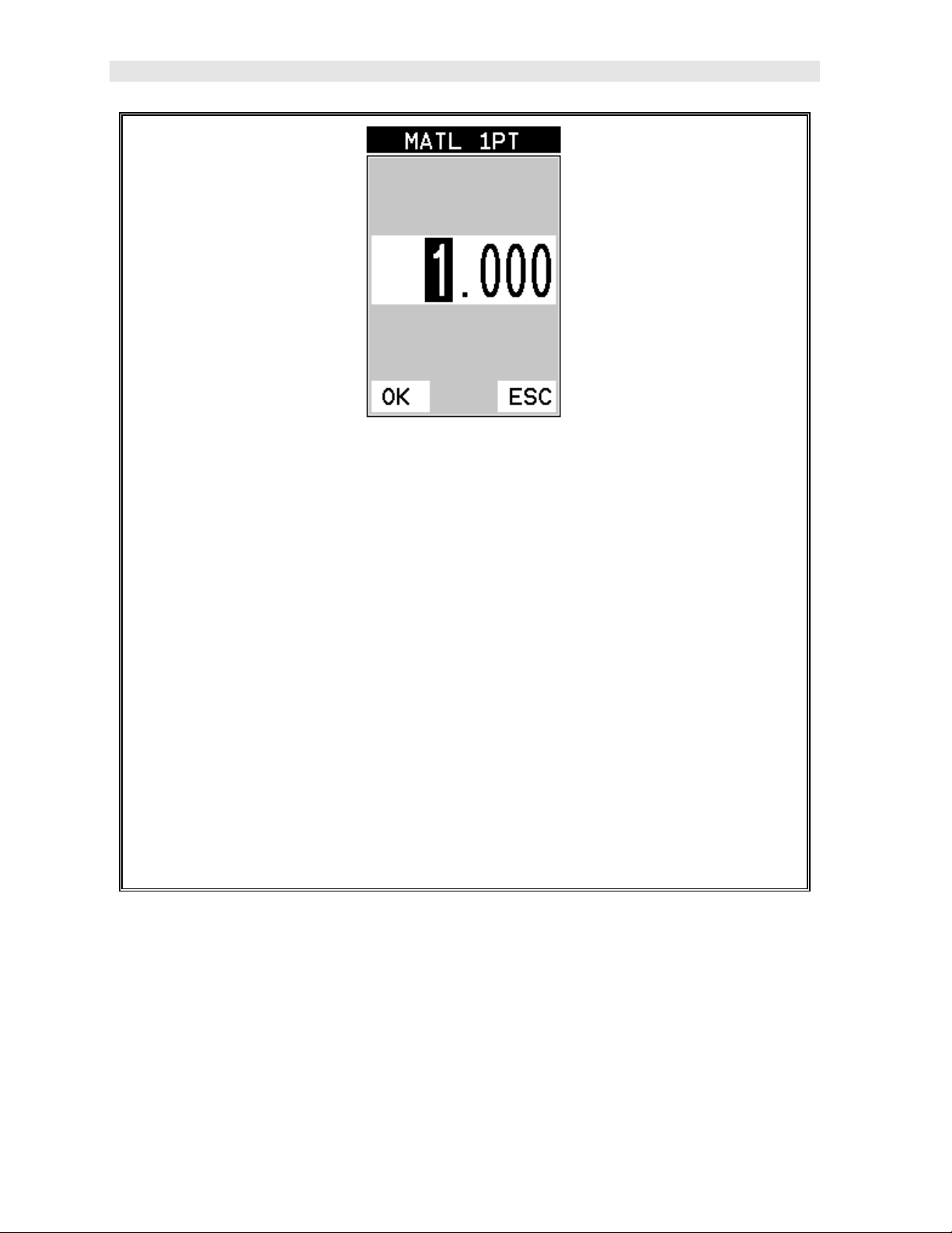
4) Press the ENTER key to display the Digits Edit Box.
5) Press the UP and DOWN arrow keys to scroll the highlighted value.
6) Press the LEFT and RIGHT arrow keys to scroll the digit locations.
7) Repeat steps 5 & 6 until the known thickness value is correctly displayed.
8) Press the OK key to calculate the velocity and return to the menu screen, or
ESC to cancel the one point calibration.
9) Finally, press the MEAS key to return to the measurement screen and begin
taking readings.
Note: CHECK YOUR CALIBRATION! Place the transducer back on the
calibration point. The thickness reading should now match the known
thickness. If the thickness is not correct, repeat the steps above.
At some point there may become a requirement for improved accuracy over a smaller
measurement range. In this case, a two point calibration would be most suited for
50
Page 55

CMX DL High Performance Material & Coating Thickness Gauge
the job. For example, if the measurement range was .080” (2.03mm) to .250”
(6.35mm), the user would perform a one point calibration on a known thickness
sample close to .250” (6.35mm), followed by a two point calibration close to .080”
(2.03mm). When a two point calibration is performed, the CMXDL calculates the zero
and the velocity. The following steps outline this procedure:
Two Point Calibration
1) Physically measure an exact sample of the material or a location directly on
the material to be measured using a set of calipers or a digital micrometer.
2) Apply a drop of couplant on the transducer and place the transducer in
steady contact with the sample or actual test material. Be sure that the
reading is stable and the repeatability indicator, in the top left corner of the
display, is fully lit and stable. Press the MENU key once to activate the
menu items tab. Press the MENU key mul tiple times to tab right and the
ESC key multiple times to tab left until the CAL menu is highlighted and
displaying the submenu items.
3) Use the UP and DOWN arrow keys to scroll through the sub menu items
until MATL 2PT is highlighted.
51
Page 56

Dakota Ultrasonics
4) Press the ENTER key to display the Digits Edit Box.
5) Press the UP and DOWN arrow keys to scroll the highlighted value.
6) Press the LEFT and RIGHT arrow keys to scroll the digit locations.
7) Repeat steps 5 & 6 until the known thickness value is correctly displayed.
8) Press the OK key to calculate the velocity and return to the menu screen, or
ESC to cancel the one point calibration.
9) Finally, press the MEAS key to return to the measurement screen and begin
taking readings.
Note: CHECK YOUR CALIBRATION! Place the transducer back on the
calibration point. The thickness reading should now match the known
thickness. If the thickness is not correct, repeat the steps above.
Basic Material Type
If the material velocity is unknown, and a sample thickness cannot be taken from the
material, the user may opt to choose a basic material type from a list with
approximate velocity values according to various material types. It’s important to
note that these velocities will not always be an exact representation of the material
52
Page 57

CMX DL High Performance Material & Coating Thickness Gauge
being tested. Use these values only if a close approximation is acceptable. Follow
the steps below to select a basic material type:
Selecting a Basic Material Type
1) Press the MENU key once to activate the menu items tab. Press the MENU
key multiple times to tab right and the ESC key multiple times to tab left until
the CAL menu is highlighted and displaying the submenu items.
2) Use the UP and DOWN arrow keys to scroll through the sub menu items
until MAT is highlighted.
3) Press the ENTER key to display the list of material types.
53
Page 58

Dakota Ultrasonics
4) Press the UP and DOWN arrow keys to scroll through the material list until
the appropriate material is highlighted.
5) Press the ENTER key to overwrite the material type and display the menu
items with the new material type selected.
6) Finally, press the MEAS key to return to the measurement screen and begin
taking readings.
To calibrate the CMXDL for a specific type of coating using samples with known
thicknesses, please refer to the chapter 9 – Pulse-Echo Coating (PECT) or
Coating (CT) for a complete explanation of using the CMXDL for coating
measurements.
54
Page 59

CHAPTER SEVEN
USING THE DIGITS & B-SCAN DISPLAYS
A key feature of the CMXDL is the ability to toggle between two different display
options, Digits and B-Scan. The Digits view provides the user with a large digital
readout of the thickness. Both views also include a scan bar features that uses a bar
graph to indicate thickness. The Scan bar can be very handy while scanning a tank
or pipe wall by graphically displaying deflections from pits or internal flaws, rather
than having to constantly watch for changes in the digital readout. It’s just another
visual aid to alarm the user when something out of the ordinary has been detected.
The B-Scan display is also very useful when scanning surfaces and viewing the cross
section of the test material. It provides a convenient way of visually profiling, or
drawing a picture of, the blind surfaces during a scan. The B-Scan display is also
equipped with a scan bar representing the overall thickness. Once again, the scan
bar gives the user a visual indication when a flaw or defect has been passed over
during the scan process. The scan bar will deflect off of the defect and return back to
the overall thickness. In this chapter we’ll outline some of the fine adjustment
features of the CMXDL. We’ll take a better look at these options in this chapter.
Note: In order to recall and use the new adjustments made to the CMXDL at a later
time, the user must save the modified settings in one of the setup locations. Refer
page 112 for more information on setups.
55
Page 60

Dakota Ultrasonics
7.1 Display Views
DIGITS VIEW
DIGITS
The Digits view is a basic digital thickness gauge look and feel. The larger digits
make it much easier for the operator to monitor the thickness readings. The Scan
Bar has also been added to the Digits view to provide the user with yet another visual
tool for easily monitoring changes in thickness readings due to internal flaws or
defects.
The following is a list of the viewable features on the display:
A. Repeatability/Stability Indicator – This indicator should be commonly used
in conjunction with the digital thickness values displayed. When all the vertical
bars are fully illuminated and the last digit on the digital thickness value is
stable, the CMXDL is reliably measuring the same value 3 to 200 times per
second, depending on which measurement mode and features are enabled.
B. Battery Icon – Indicates the amount of battery life the CMXDL has remaining.
C. Velocity – The material velocity value the CMXDL is currently using or
calibrated for. Displayed in English or Metric units, depending on the what
units the gauge is set for.
D. Feature Status Bar – Indicates the features currently enabled and in use in
the following order:
• Measurement Mode
• Differential Mode
• High Speed Scan Mode
56
Page 61

CMX DL High Performance Material & Coating Thickness Gauge
• Alarm Mode
• Gain Setting
E. Digital Material Thickness Value – Extra large font size for viewing ease.
F. Scan Bar – Another view of material thickness in a deflection style horizontal
bar. This is another visual tool that would enable the user the ability to see
thickness changes during high speed scans from flaws and pits.
G. Units – The current measurement units being used (English, Metric).
H. Coating Thickness Value – Displays the actual thickness of any coating
adhered to a metallic material surface (PECT Mode), or a coating adhered to a
non-metallic surface (CT Mode).
I. Minimum Material Thickness – Part of the Alarm feature. Displays the
minimum thickness value found during a scan.
J. Maximum Material Thickness – Part of the Alarm feature. Displays the
maximum thickness value found during a scan.
B-Scan View
B-Scan
The B-Scan displays a time based cross section view of test material. This view is
commonly used to display the contour of the blind, or underside, surface of a pipe or
tank application. It is very similar to a fish finder. If a flaw or pit is located during a
scan, the B-Scan will draw the pit on the screen. The solid black rectangle in the
diagram at location K represents the cross section, or side view of the material. The
B-Scan view draws at a rate of 7 seconds per screen from right to left. Also notice at
location K, the pits and corroded bottom surface of the material.
It’s important to note that the measurement range on the display be set wide enough,
so that the maximum thickness of the material can be viewed on the display. Using
the diagram above, if the material thickness was actually 1.75”, the underside of the
material would not be viewable according to the current range at 0.00” – 1.00”. All
57
Page 62

Dakota Ultrasonics
the user would see is a black screen from 0.00” – 1.00” with no view of the bottom
contour at 1.75”.
The following is a list of the viewable features on the display:
A. Repeatability/Stability Indicator – This indicator should be commonly used
in conjunction with the digital thickness values displayed. When all the vertical
bars are fully illuminated and the last digit on the digital thickness value is
stable, the CMXDL is reliably measuring the same value 3 to 200 times per
second, depending on which measurement mode and features are enabled.
B. Battery Icon – Indicates the amount of battery life the CMXDL has remaining.
C. Velocity – The material velocity value the CMXDL is currently using or
calibrated for. Displayed in either English or Metric units, depending on the
what units the gauge is set for.
D. Feature Status Bar – Indicates the features currently enabled and in use in
the following order:
• Measurement Mode (P-E, PECT, PETP, E-E, COAT)
• Differential Mode (ON/OFF)
• High Speed Scan Mode (ON/OFF)
• Alarm Mode (ON/OFF/AUDIBLE)
• Gain Setting (VLOW, LOW, MED, HI, VHI)
E. Digital Material Thickness Value – Smaller font size when the B-Scan
display view is enabled.
F. Scan Bar – Another view of material thickness in a deflection style horizontal
bar. This is another visual tool that would enable the user the ability to see
thickness changes during high speed scans from flaws and pits.
G. Units – The current measurement units being used (English, Metric).
H. Coating Thickness Value – Displays the actual thickness of any coating
adhered to a metalli c material surface (PECT Mode), or a coating adhered to a
non-metallic surface (CT Mode).
I. Minimum Material Thickness – Part of the Alarm feature. Displays the
minimum thickness value found during a scan.
J. Maximum Material Thickness – Part of the Alarm feature. Displays the
maximum thickness value found during a scan.
K. B-Scan Display – Cross section view of the material. Provides the user with
graphical view of the opposite/blind surface (i.e. inside pipe wall surface), to
give the user some idea of the condition, or integrity of the material being
tested.
58
Page 63

CMX DL High Performance Material & Coating Thickness Gauge
7.2 Activating B-Scan View
To use the B -Scan feature it must be enabled in the display menu. The following
steps will help you do just that:
Enabling the B- Scan Feature
1) Press the MENU key once to activat e the menu items tab. Press the MENU
key multiple times to tab right, and the ESC key multiple times to tab left,
until the DISP menu is highlighted and displaying the submenu items.
2) Use the UP and DOWN arrow keys to scroll through the sub menu items
until VIEW is highlighted.
3) Press the LEFT and RIGHT arrow keys to toggle DIGITS or BSCAN. When
the correct view is being displayed continue on to setting the B-START or B-
DEPTH values, or press the MEAS key to return to the measurement screen
and begin taking readings.
59
Page 64

Dakota Ultrasonics
7.3 Adjusting the B-Scan Start (B-START) & Depth (B-DEPTH)
In order to use the B-Scan and Scan Bar features of the CMXDL effectively, the
starting depth and overall depth must be setup correctly. This can be adjusted using
the B-START and the B-DEPTH features of the CMXDL. The B-START refers to the
starting depth or thickness value displayed. Example: If you want your B-Scan or
Scan Bar to start at a zero thickness value, then B-START must be set to 0.000”. If
you want the B-Scan and Scan Bar to start displaying at .125”, then B-START must
be set to .125”. B-DEPTH represents overall viewable thickness range being tested.
Example: If your measuring tank walls with a total thickness of .300”, and your B-
START has been set to 0.000”, you might consider setting your B-DEPTH value to
something like 0.400” to cover the entire thickness range being tested. You might
also consider B-DEPTH as a zoom feature for both the B-Scan and Scan Bar. Why?
Because the larger the overall thickness range view (B-DEPTH), the smaller the
noticeable shifts in the Scan Bar and B-Scan presentation. Therefore, it’s best to set
the B-START and B-DEPTH to reasonable values that zoom in and optimize your
graphic presentation.
Starting depth (B-START)
The starting B-START, or starting depth, is the starting thickness value. Often times
this value will simply be set to zero in order to start measuring at 0.000”. The only
time this value will be set to something other than zero, is if the user needs to zoom
in even closer. When will this be the case? If the user is testing a material that’s 1
inch in thickness and knows that the potential corrosion is only on the back surface of
the material and not possibly deeper than .200”. In this case, the user may wish to
set the B-ST at .700” to zoom in closer to the actual area being tested. In turn, the BDEP might be set at 1.100” in order to cover the entire range respectively. This will
offer the user better resolution for both the B-Scan and Scan Bar graphical
presentations.
Note: Once the range is set, it will remain the same for all the views respectively.
The procedures to adjust the starting depth (B-START) are outlined below:
60
Page 65

CMX DL High Performance Material & Coating Thickness Gauge
Adjusting the Starting Depth (B-START)
1) Press the MENU key once to activate the menu items tab. Press the MENU
key multiple times to tab right, and the ESC key multiple times to tab left,
until the DISP menu is highlighted and displaying the submenu items.
2) Use the UP and DOWN arrow keys to scroll through the sub menu items
until B-START is highlighted.
3) Press the LEFT and RIGHT arrow keys to scroll the value. When the
correct B-Start value is being displayed, proceed to step 8.
4) Alternatively, press the ENTER key to display the Digits Edit Box.
61
Page 66

Dakota Ultrasonics
5) Press the UP and DOWN arrow keys to scroll the h ighlighted value.
6) Press the LEFT and RIGHT arrow keys to scroll the digit locations.
7) Repeat steps 5 & 6 until the B-Start value is correctly displayed.
8) Press the OK key to set the B-Start value and return to the menu screen, or
ESC to cancel entering the B-Start.
9) Finally, press the MEAS key to return to the measurement screen and begin
taking readings.
Overall range (B-DEPTH)
Once again, just to reiterate, B-DEPTH is the overall viewable thickness range being
tested. This should be set to a value slightly larger then the expected maximum
range being measured. The procedures to adjust the overall thickness range viewed
(B-DEPTH) are outlined below:
Adjusting the Overall Depth (B-DEPTH)
1) Press the MENU key once to activate the menu items tab. Press the MENU
key multiple times to tab right, and the ESC key multiple times to tab left,
until the DISP menu is highlighted and displaying the submenu items.
62
Page 67

CMX DL High Performance Material & Coating Thickness Gauge
2) Use the UP and DOWN arrow keys to scroll through the sub menu items
until B-DEPTH is highlighted.
3) Press the LEFT and RIGHT arrow keys to scroll the value. When the
correct width is being displayed, proceed to step 8.
4) Alternatively, press the ENTER key to display the Digits Edit Box.
5) Press the UP and DOWN arrow keys to scroll the highlighted value.
6) Press the LEFT and RIGHT arrow keys to scroll the digit locations.
7) Repeat steps 5 & 6 until the B-Depth value is correctly displayed.
8) Press the OK key to set the B-Depth and return to the menu screen, or ESC
to cancel entering the B-Depth.
9) Finally, press the MEAS key to return to the measurement screen and begin
taking readings.
63
Page 68

Dakota Ultrasonics
7.4 Gain
The gain, or amplification of the return echoes, can be adjusted in the CMXDL to
accommodate a variety of applications. The setting of the gain is crucial in order to
obtain valid readings during the measurement process. Too much gain may result in
erroneous measurements, by detecting on noise rather than the actual material back
wall itself. Not enough gain may result in intermittent detection. It may also result in
lack of detection on internal flaws, pits, or porosity. The gain can easily be compared
to the volume control of a home stereo system. If you turn it up too much, you can’t
hear the music clearly. If it’s turned down too much, you can’t hear it at all.
The CMXDL has three gain settings (VLOW, LOW, MED, HI, VHI). The gain range is
42dB – 50dB in 2dB increments. Note: The CMXDL has been optimized for the MED
gain setting for all common applications. It should be operated in this mode as
standard. However, some applications may require the lower or higher gain settings.
When? The low settings may be necessary for noisy or granular cast materials. How
do I know when to lower the gain? If the reading becomes sporadic and won’t settle
down or resolve on a thickness value, the user can assume that the material is either
very noisy aluminum, or granular cast iron. This would be a good time to change the
CMXDL to low er gain setting and see if the reading settles down and become stable.
How do I know when to increase the gain? Often times the user will be trying to
measure a material that is hard to penetrate or pass sound through. This may be
due to the material type, or overall thickness of the material. When a material is hard
to pass sound through because of the thickness or general make-up, it would be a
good time to consider switching the CMXDL into a higher gain setting. Another
example might be the need to increase overall sensitivity for locating fine pits or
flaws. In any case, the selectable gain settings offer the user some additional options
to resolve and overcome application issues.
Note: When the echo-echo thru-paint measurement mode is selected, the manual
gain feature is disabled and grayed out in the menu items. In this mode, the CMXDL
switches to an automatic gain mode (AGC) that optimizes the gain setting
automatically in the hardware of the CMXDL.
The procedures to adjust the Gain are outlined below:
64
Page 69

CMX DL High Performance Material & Coating Thickness Gauge
Adjusting the Gain
1) Press the MENU key once to activate the menu items tab. Press the
MENU key multiple times to tab right, and the ESC key multiple times to tab
left, until the TUNE menu is highlighted and displaying the submenu items.
2) Use the UP and DOWN arrow keys to scroll through the sub menu items
until GAIN is highlighted.
3) Press the LEFT and RIGHT arrow keys to scroll the value. When the
correct Gain is being displayed, press the MEAS key to return to the
measurement screen and begin taking readings.
65
Page 70

CHAPTER EIGHT
THRU PAINT MEASUREMENT TECHNIQUE
8.1 Introduction to Thru Paint Measurement
The principle behind thru paint measurement is by measuring the time between two
backwall echoes returning from the test material. Since both of these backwall
echoes travel the same path through the paint or coating, the thickness of the coating
is subtracted out of the measurement so that only the actual material thickness can
be measured. This feature saves the user a great deal of time scraping and
removing the coating from tanks and pipes during the inspection process.
The primary purpose of thru paint measurement is to determine actual or overall
material thickness by eliminating the coating thickness. Thru paint mode cannot be
used for flaw or pit detection. Therefore, inspectors may need to use echo-echo thru
paint mode in conjunction with the standard pu lse-echo flaw detection mode for some
applications. Chassis tubing inspectors and sanctioning bodies will use the echoecho mode for tubing with powder coatings, and pulse-echo mode for tubing without
coating. The combination of using both modes is ideal for the advanced inspectors
needs.
8.2 Using Thru Paint Mode
The first thing to note in this section, is that by selecting the transducer type from the
list of probes stored in the CMXDL, a basic echo-echo thru paint configuration is
recalled from memory. Each of the transducers in the list contain s pre-configured
echo-echo settings. The standard transducer that will be used for common steel
applications is a ¼” 5MHz high damped transducer (1/4IN – 5.0MHZ HD) . This is the
recommended transducer for this industry and should be used for thru paint
applications. Any of the auto recognition coating transducers are also high damped
transducers and will work in echo-echo mode as well.
Note: When a transducer is selected for use, all of the measurement modes
available for use with this transducer can easily be determined by pressing the multimode button on the keypad. The CMXDL has been programmed to identify the
modes available to a specific transducer.
Once the transducer type has been selected and the appropriate calibration
procedure completed, the CMXDL can toggle between pulse-echo (flaws & pits), and
echo-echo (thru paint) modes by simply pressing the MULTI MODE key located on
the keypad. Refer to page 39 for additional information.
The CMXDL can also be configured for thru paint applications by selecting a factory
setup stored in the list of setups in the CMXDL. Refer to page 112 for information on
recalling a setup. Once either the transducer type or setup has been selected, the
inspector is ready to begin making measurements.
66
Page 71

CHAPTER NINE
PULSE-ECHO COATING & COATING TECHNIQUES
9.1 Introduction to Pulse- Echo Coating Measurement (PECT)
In the previous sections we’ve discussed the need for detecting pits and flaws (pulseecho) in materials, along with the requirement to measure through and eliminate
errors caused by coated materials (echo-echo). Until now, both modes were needed
in order accomplish both tasks. Pulse-echo mode was used for flaw detection, an d
echo-echo mode was used to eliminate the coating thickness and provide a nominal
material thickness only. With this in mind, it often became cumbersome toggling
between both modes respectively.
In a majority of applications involving coat ed materials, inspectors are often
interested in monitoring both the thickness of the material, as well as the thickness of
the coating. Therefore, the CMXDL has been designed to provide the user with the
ability to measure the material and coating thicknesses simultaneously, while
maintaining the ability to detect flaws and pits all in a single mode called Pulse-Echo
Coating (PECT) . This is accomplished by using a custom hybrid combination mode
utilizing properties from the basic modes along with a group of special techniques
and theoretical wave phenomena’s.
The CMXDL is preset to a coating velocity of 0.0850 in/µsec (2159 m/sec) from the
factory. This velocity is a very close approximation of the common coating velocities
found in the field. However, the CMXDL also has a built -in one and two point
calibration options to calibrate to coating samples with a known thicknesses.
There are two coating modes built into the CMXDL:
1) Pulse-Echo Coating (PECT) – used during inspections where both the
material and coating thicknesses are required.
2) Coating Only (CT) – used during inspections where only the coating thickness
is required.
9.2 Enabling Pulse-Echo Coating Mode (PECT) & Coating (CT)
When the CMXDL is initially powered up, the gauge will automatically check to see if
the transducer plugged into the gauge can be recognized. All Dakota Ultrasonics
coating enabled transducers are equipped with the auto recognition feature. If the
CMXDL doesn’t recognize that a special coating enabled transducer is plugged into
the gauge, the coating feature will be disabled entirely. There are a number of
coating enabled transducers available from Dakota. Please contact us with your
application requirements for additional information on frequencies and diameters
currently offered.
The coating modes can be enabled in three different ways:
1) On Power up and probe recognition.
2) By pressing MULTI MODE keypad.
67
Page 72

Dakota Ultrasonics
3) From the tabbed menus under TUNE, MEASURE MODE.
The steps that follow will demonstrate all three methods in the order listed above:
Probe Aut omatically Recognized (PECT only)
1) Press the OK key once to use the identified probe, or ESC to display a list of
optional transducers. Note: if the CMXDL recognizes a specific transducer,
the user should always select OK to use the identified probe. The only time
an alternative probe should be selected from a list is if the user switched
probes following initial power up and recognition.
2) Assuming the CMXDL recognized the probe and the OK key was pressed,
the CMXDL will advance to a Zero Probe menu. If the transducer was
identified as a special transducer capable of measuring coating thickness, a
menu will be displayed allowing the user the ability to toggle the coating
thickness display on/off as follows:
68
Page 73

CMX DL High Performance Material & Coating Thickness Gauge
3) Press the UP and DOWN arrow keys to toggle th e coating option on/off.
Multi Mode Key Pressed (PECT & CT)
Applied to Metals Not Applied to Metals
1) Press the MULTI MODE key located on bottom left of the keypad to display
the MEASURE MODE options menu.
2) Press the UP and DOWN arrow keys to highlight the COATING ON (PECT)
or COATING ONLY (CT) menu option.
69
Page 74

Dakota Ultrasonics
3) Press the ENTER key to enable the coating option, or ESC to cancel
changing the measure mode, and return to the main measurement screen.
Measure Mode (Tabbed Menus) – (PECT & CT)
Applied to Metals Not Applied to Metals
1) Press the MENU key once to activate the menu items tab. Press the MENU
key multiple times to tab right, and the ESC key multiple times to tab left,
until the TUNE menu is highlighted and displaying the submenu items.
2) Use the UP and DOWN arrow keys to scroll through the sub menu items
until MEASURE MODE is highlighted.
3) Press the LEFT and RIGHT arrow keys to scroll the modes.
4) When the correct MODE is being displayed, press the MEAS key to return
to the measurement screen and begin taking readings.
70
Page 75

9.3 Zero Coating
CMX DL High Performance Material & Coating Thickness Gauge
In order to account for very slight electronic differences in transducers of the same
type, frequency, and diameter, the CMX
feature. This enables the CMX
DL+
to obtain very accurate readings on coatings,
DL+
has been equipped with a “zero coating”
eliminating potential errors incurred from slight differences in the manufacturing
processes. The procedure is outlined below:
Performing a Coating Zero
1) Press the MULTI MODE key once to activate the measurement mode
options.
2) Use the UP and DOWN arrow keys to scroll through the sub menu items
until Coating Only (CT) mode is highlighted.
3) Press the ENTER key to select the measurement mode and return to the
measurement screen.
4) Apply a drop of couplant on the transducer and place the transducer in
steady contact with the probe zero disk (battery cover) and obtain a steady
reading.
Note: The coating measurement displayed will potentially be a value greater or
less than 0.
71
Page 76

Dakota Ultrasonics
5) Press the MENU key once to activate the menu items tab. Press the MENU
key multiple times to tab right and the ESC key multiple times to tab left until
the PRB menu is highlighted and displaying the submenu items.
6) Use the UP and DOWN arrow keys to scroll through the sub menu items
until ZERO COATING is highlighted.
7) Press the ENTER key to display the confirmation screen.
8) Press the OK key to zero the coating and return to the PRB menu, or ESC
to cancel the coating zero process.
9) Press the MULTI MODE key once to activate the measurement mode
options.
10) Use the UP and DOWN arrow keys to scroll through the sub menu items
until Coating On (PECT) is highlighted.
11) Press the ENTER key to select the measurement mode and return to the
measurement screen, and begin taking readings. Proceed to the coating
calibration section.
72
Page 77

CMX DL High Performance Material & Coating Thickness Gauge
9.4 Coating Calibration (PECT)
Known Velocity
If the coating velocity is known, the user may wish to simply enter the velocity
number into the CMXDL, rather than have the CMXDL calculate the velocity value
using a known thickness on a coating sample(s). The steps for entering the velocity
are outlined below:
Using a Known Material Velocity
1) Press the MENU key once to activate the menu items tab. Press the MENU
key multiple times to tab right and the ESC key multiple times to tab left until
the CAL menu is highlighted and displaying the submenu items.
2) Use the UP and DOWN arrow keys to scroll through the sub menu items
until COATING VEL is highlighted.
73
Page 78

Dakota Ultrasonics
3) Press the ENTER key to display the Digits Edit Box.
4) Press the UP and DOWN arrow keys to scroll the highlighted value.
5) Press the LEFT and RIGHT arrow keys to scroll the digit locations.
6) Repeat steps 4 & 5 until the velocity number is correctly displayed.
7) Press the OK key to set the velocity and return to the menu screen, or ESC
to cancel entering the velocity.
8) Finally, press the MEAS key to return to the measurement screen and begin
taking readings.
74
Page 79

CMX DL High Performance Material & Coating Thickness Gauge
Known Thickness
Sometimes the sound velocity of a coating material is unknown. In this case a
sample with a known thickness can be used to determine the sound velocity of the
coating. As previously discussed, the CMXDL offers a one point calibration option for
coating in PECT measurement mode. It is also import to reiterate that the coating
sample must be coupled to a metallic material in order to perform the calibration .
The calibration shou ld also consider calibrating on high side of the intended
measurement range, when using the one point option, minimize overall error. For
example, if the measurement range of the coating will be from .040” - .080” (1.0mm
2.3mm), a coating closest to .080 (2.0mm) should be used. Note: It’s always handy
to carry a set of mechanical calipers to use in conjunction with the CMXDL for
calibration in the field:
One Point Calibration
Note: Be sure that the probe zero procedure has been performed prior to
performing this calibration procedure.
1) Physically measure an exact sample of the coating using a set of calipers or
a digital micrometer.
Note: The coating sample must be coupled to a metallic material in order to be
calibrated.
2) Apply a drop of couplant on a piece of metal and place the coating sample
on the metal over the couplant. Apply a drop of couplant on the transducer
75
Page 80

Dakota Ultrasonics
and place the transducer in steady contact with the coating and sample or
actual test material. Be sure that the reading is stable and the repeatability
indicator, in the top left corner of the display, is fully lit and stable. Press the
MENU key once to activate the menu items tab. Press the MENU key
multiple times to tab right and the ESC key multiple times to tab left until the
CAL menu is highlighted and displaying the submenu items.
3) Use the UP and DOWN arrow keys to scroll through the sub menu items
until COATING 1PT is highlighted.
4) Press the ENTER key to display the Digits Edit Box.
5) Press the UP and DOWN arrow keys to scroll the highlighted value.
6) Press the LEFT and RIGHT arrow keys to scroll the digit locations.
7) Repeat steps 5 & 6 until the known thickness value is correctly displayed.
8) Press the OK key to calculate the velocity and return to the menu screen, or
ESC to cancel the coating one point calibration.
9) Finally, press the MEAS key to return to the measurement screen and begin
taking readings.
76
Page 81

CMX DL High Performance Material & Coating Thickness Gauge
Note: CHECK YOUR CALIBRATION! Place the transducer back on the
calibration point. The coating thickness reading should now match the known
thickness. If the thickness is not correct, repeat the steps above.
9.5 Introduction to Coating Measurement (CT)
In the previous sections we’ve discussed how to setup and use the coating feature
for use in conjunction with material thickness and flaw and pit detection. The CMXDL
also has the capability to be used for general coating measurements. This
measurement mode is called Coating (CT) and can be enabled using the same
methods as described in a previous section above.
When the Coating Only (CT) mode is enabled, a two point calibration on the coating
samples must be performed. This is to ensure linearity over the coating
measurement range will be achieved. Important note: If coating measurements will
be made with the coating applied to a metal surface, the calibration must be done in
the same manner, with the samples coupled to a metal surface. However, if the
coating will be measured as a stand alone material, the calibration must be
performed the same way .
9.6 Two Point Coating Calibration (CT)
Known Thickness
The following section will demonstrate the two point coating calibration procedure.
This example demonstrates a coating thickness range of .040” - .120” (1 – 3 mm) as
follows:
Note: It’s always handy to carry a set of mechanical calipers to use in conjunction
with the CMXDL for calibration in the field:
77
Page 82

Dakota Ultrasonics
One Point Calibration
Note: Use the maximum coating sample for the one point calibration first.
1) Physically measure the thicker of the two samples of coating, as close as
possible to the maximum expect ed coating measurement range, using a set
of calipers or a digital micrometer.
Very Important : If coating measurements will be made with the coating
applied to a metal surface, the calibration must be done in the same manner,
with the samples coupled to a metal surface. However, if the coating will be
measured as a stand alone material, the calibration must be performed the
same way.
2) Apply a drop of couplant on the transducer and place the transducer in
steady contact with the thicker of the two coating and samples fist. Be sure
that the reading is stable and the repeatability indicator, in the top left corner
of the display, is fully lit and stable. Press the MENU key once to activate
the menu items tab. Press the MENU key multiple times to tab right and the
ESC key multiple times to tab left until the CAL menu is highlighted and
displaying the submenu items.
78
Page 83

CMX DL High Performance Material & Coating Thickness Gauge
3) Use the UP and DOWN arrow keys to scroll through the sub menu items
until COATING 1PT is highlighted.
4) Press the ENTER key to display the Digits Edit Box.
5) Press the UP and DOWN arrow keys to scroll the highlighted value.
6) Press the LEFT and RIGHT arrow keys to scroll the digit locations.
7) Repeat st eps 5 & 6 until the known thickness value is correctly displayed.
8) Press the OK key to calculate the velocity and return to the menu screen, or
ESC to cancel the coating one point calibration.
9) Finally, press the MEAS key to return to the measurement screen and begin
taking readings.
79
Page 84

Dakota Ultrasonics
Two Point Calibration
Note: Use the minimum coating sample for the two point calibration.
1) Physically measure the thinner of the two samples of the coating, as close
as possible to the minimum expected coating measurement range, using a
set of calipers or a digital micrometer.
Very Important : If coating measurements will be made with the coating
applied to a metal surface, the calibration must be done in the same manner,
with the samples coupled to a metal surface. However, if the coating will be
measured as a stand alone material, the calibration must be performed the
same way.
2) Apply a drop of couplant on the transducer and place the transducer in
steady contact with the thinner of the two coating and samples. Be sure that
the reading is stable and the repeatability indicator, in the top left corner of
the display, is fully lit and stable. Press the MENU key once to activate the
menu items tab. Press the MENU key multiple times to tab right and the
ESC key multiple times to tab left until the CAL menu is highlighted and
displaying the submenu items.
80
Page 85

CMX DL High Performance Material & Coating Thickness Gauge
3) Use the UP and DOWN arrow keys to scroll through the sub menu items
until COATING 2PT is highlighted.
4) Press the ENTER key to display the Digits Edit Box.
5) Press the UP and DOWN arrow keys to scroll the highlighted value.
6) Press the LEFT and RIGHT arrow keys to scroll the digit locations.
7) Repeat steps 5 & 6 until the known thickness value is correctly displayed.
8) Press the OK key to calculate the velocity and return to the menu scr een, or
ESC to cancel the coating one point calibration.
9) Finally, press the MEAS key to return to the measurement screen and begin
taking readings.
Note: CHECK YOUR CALIBRATION! Place the transducer back on both
calibration points. The coating thickness readings should now match the known
thickness values of each sample. If the thickness is not correct, repeat the
steps above.
81
Page 86

CHAPTER TEN
ADDITIONAL FEATURES OF THE CMXDL
10.1 High Speed Scan
The High Speed Scan feature of the CMXDL increases the overall repetition rate to a
maximum of 140Hz with a high speed screen refresh rate of 25 times a second. This
feature enables a user to make scanned passes over an arbitrary length of the test
material, while still maintaining a reasonable representation of thickness over th e
scanned area or region. This feature can be used in conjunction with High and Low
alarm limits features to dynamically keep track of both values. The feature is typically
used to provide a better representation of the area scanned, by taking more readings
at a faster rate repetition rate.
The procedure to use the SCAN MODE feature is outlined below:
Using the Scan Mode
1) Press the MENU key once to activate the menu items tab. Press the MENU
key multiple times to tab right and the ESC key multiple tim es to tab left until
the UTIL menu is highlighted and displaying the submenu items.
2) Use the UP and DOWN arrow keys to scroll through the sub menu items
until SCAN MODE is highlighted.
3) Use the LEFT and RIGHT arrow keys to toggle the SCAN MODE on/off.
82
Page 87

CMX DL High Performance Material & Coating Thickness Gauge
4) Press the MEAS key to return to the measurement screen.
10.2 Alarm Mode
The Alarm Mode feature of the CMXDL provides the user with a method of setting
tolerances, or limits, for a particular application requirement. This feature may be
used for a variety of applications to verify the material is within the manufacturer
specifications. There are two limits, or alarm values, that can be setup in the CMXDL
– ALARM LOW and ALARM HIGH limits. However, the user may choose to activate
and utilize only one of the limit va lues, depending on their specific application
requirements. The procedures to use the ALARM MODE feature are outlined below:
Toggle Alarm (on/off)
1) Press the MENU key once to activate the menu items tab. Press the MENU
key multiple times to tab right, and the ESC key multiple times to tab left,
until the UTIL menu is highlighted and displaying the submenu items.
2) Use the UP and DOWN arrow keys to scroll through the sub menu items
until ALARM is highlighted.
3) Use the LEFT and RIGHT arrow keys to toggle the ALARM on/off/audible.
4) Continue on to the next section “Setting the Alarm Low Limit”.
83
Page 88

Dakota Ultrasonics
Setting the Alarm Low Limit
1) Assuming the ALARM is ON, use the UP and DOWN arrow keys to scroll
through the sub menu items until ALARM LOW is highlighted.
2) Press the LEFT and RIGHT arrow keys to scroll the value. When the
correct alarm value is being displayed, proceed to step 7.
3) Alternatively, press the ENTER key to display the Digits Edit Box.
4) Press the UP and DOWN arrow keys to scroll the highlighted value.
5) Press the LEFT and RIGHT arrow keys to scroll the digit locations.
84
Page 89

CMX DL High Performance Material & Coating Thickness Gauge
6) Repeat steps 4 & 5 until the ALARM LOW value is correctly displayed.
7) If only one limit will be used, press the MEAS key to return to the
measurement screen and begin taking readings. Otherwise, continue on to
set the ALARM HIGH limit.
10.3 Differential Mode
The Differential Mode of the CMXDL provides the user with the ability to set a
nominal value, according to what the expected thickness should be, and measure the
+/- difference from the nominal va lue entered. This feature is typically used in QA
incoming inspections on pipes, plate stock, coils, etc. The steps below outline how to
enable and enter the nominal value to use this feature:
Toggle Differential (on/off)
1) Press the MENU key once to activate the menu items tab. Press the MENU
key multiple times to tab right, and the ESC key multiple times to tab left,
until the UTIL menu is highlighted and displaying the submenu items.
2) Use the UP and DOWN arrow keys to scroll through the sub menu items
until DIFFERENTIAL is highlighted.
85
Page 90

Dakota Ultrasonics
3) Use the LEFT and RIGHT arrow keys to toggle the DIFFERENTIAL on. A
value will appear to the right of DIFFERENTIAL.
4) Continue on to the next section “Setting the Differential Value”.
Setting the Differential Value
1) Assuming DIFFERENTIAL has been enabled and a value is being displayed
to the right of the DIFFERENTIAL label, press the ENTER key to display the
Digits Edit Box.
2) Press the UP and DOWN arrow keys to scroll the highlighted value.
3) Press the LEFT and RIGHT arrow keys to scroll the digit locations.
4) Repeat steps 2 & 3 until the DIFFERENTIAL value is correctly displayed.
5) Press the OK key to set the DIFFERENTIAL value and return to the menu
screen.
6) Finally, press the MEAS key to return to the measurement screen and begin
taking readings.
86
Page 91

CHAPTER ELEVEN
DATA STORAGE – SETUP, EDIT, & VIEW FILES
11.1 Introduction to Grid and Sequential file formats
The CMXDL is equipped with two data file format options, GRID LOG and SEQ LOG.
The GRID file format is very similar to a spreadsheet format found in popular
software programs like Excel. A GRID is simply a table of readings. A location in a
grid is specified by giving a row and column coordinate. The rows are numbered
from 1 to 999 and the columns are labeled from A to ZZ (999 Rows & 52 Colu mns).
The sequential file format can be viewed as a file as a single column of up to 512
possible rows (readings), and a column of corresponding identifiers associated with
each individual reading. The identifier can be a combination of up to 10 numeric,
alpha, or special characters listed above, while the file name can consist of a
combination of up to 20 of the same character set. Note: The identifier cannot start
or end with a special character. Once a start and end ID are entered into the CMXDL
and the log created, the CMXDL will automatically generate all the identifiers within
that range.
The following character set listed below are all the allowable characters that will be
used for both file formats: GRID & SEQ LOG. Any combination of these characters
can be used for creating a Name and Note regardless of the selected format. The
allowable characters are as follows:
Numeric characters: 0 – 9 Alpha Characters: A – Z
Special Characters: ! ‘ _ # space / . – ( )
Multiple grids can be created and stored until the CMXDL’s memory is full. If the user
attempts to store a new file in the CMXDL and the size of the file exceeds the capacity
of memory, the CMXDL will respond with an error message indicating that the memory
is unable to store the new file.
The CMXDL can store a total of 16,000+ readings with a corresponding screenshot of
the DIGITS or B-SCAN views with every reading, as well as all the CMXDL settings
for every individual reading. If the graphics option is disabled, not saving
screenshots, the CMXDL can store a total of 210,000+ readings. The screenshot
stored with the reading will depend on what view the CMXDL was in at the time it was
saved. For example, if the view was in B-SCAN, then a B-SCAN will be saved with
the reading.
In the sections that follow, the procedures for creating, using, and editing GRID’s and
SEQ LOG’s have been combined together for the purpose of similarity in overall
87
Page 92

Dakota Ultrasonics
functionality and structure. The illustrations below are snapshots of typical GRID and
SEQ LOG file formats:
Grid File Formats
Sequential Log Formats
Important Note: For the duration of this chapter, all references to GRIDS and SEQ
LOGS should be considered synonymous with references to FILES.
11.2 Creating a new Grid or Seq uential Log (File)
Important Note: This entire section is a step by step guide to successfully create a
grid or sequential log. The instructions must be used in the sequential order
specified, as follows:
88
Page 93

CMX DL High Performance Material & Coating Thickness Gauge
Creating a Name
Grid/Seq Log Name : Can contain a combination of up to 20 numeric, alpha,
or special characters listed in the first section of this chapter.
Grid Log Sequential Log
1) Press the MENU key once to activate the menu items tab. Press the MENU
key multiple times to tab right, and the ESC key multiple times to tab left,
until the DATA menu is highlighted and displaying the submenu items.
2) Use the UP and DOWN arrow keys to scroll through the sub menu items
until NEW is highlighted.
3) Press the LEFT & RIGHT arrow keys to toggle the data formats – GRIG
LOG & SEQ LOG.
89
Page 94

Dakota Ultrasonics
Grid Log Sequential Log
4) Press the ENTER key to display the new Grid or Seq Edit Box.
5) Use the UP and DOWN arrow keys to scroll through the new Grid or Seq
List Items until NAME is highlighted.
6) Press the ENTER key to activate the Alpha Edit Box.
7) Use the UP, DOWN, LEFT, & RIGHT arrow keys to highlight the appropriate
alpha characters.
8) Press the ENTER key to select a character and advance to the next field of
the Grid or Seq Name.
90
Page 95

CMX DL High Performance Material & Coating Thickness Gauge
9) Use the CLR key to backspace if necessary.
10) Repeat steps 6 - 9 until the Grid or Seq Name (File Name) is completed.
11) Press the OK key to save the Grid or Seq Name and return to the Grid or
Seq List Items menu, or ESC to cancel entering the Grid or Seq Name
(File Name).
Creating a Note
Grid/Seq Log Note: Can contain a combination of up to 20 numeric, alpha, or
special characters listed in the first section of this chapter.
Grid Log Sequential Log
1) Assuming the Grid or Seq List Items are displayed, u se the UP and DOWN
arrow keys to scroll through the new Grid or Seq List Items until NOTE is
highlighted.
2) Press the ENTER key to activate the Alpha Edit Box.
91
Page 96

Dakota Ultrasonics
3) Use the UP, DOWN, LEFT, & RIGHT arrow keys to highlight the appropriate
alpha characters.
4) Press the ENTER key to select a character and advance to the next field of
the Grid or Seq Note.
5) Use the CLR key to backspace if necessary.
6) Repeat steps 3 through 5 until the Grid or Seq Note is completed.
7) Press the OK key to save the Grid or Seq Note and return to the Grid or
Seq List Items menu, or ESC to cancel entering the Grid or Seq Note.
Setting the Coordinates or Start & Stop ID’s
Grid: A grid is defined by using coordinates to define the Top Left and the
Bottom Right corners of the grid. Alpha coordinates are horizontal across the
top, and numeric coordinates are vertical down the side. Therefore, to define
the top left corner of the grid, there will be an (X,Y) coordinate. Where X is an
alpha column location across the top and Y is a numeric row location down the
side. Use the same logic when choosing the lower right corner. An individual
grid can be up to 999 rows and 52 columns.
92
Page 97

CMX DL High Performance Material & Coating Thickness Gauge
Sequential: The sequential file format can be viewed as a file as a single
column of up to 512 possible rows (readings), and a column of corresponding
identifiers associated with each individual reading. The identifier can be a
combination of up to 10 numeric, alpha, or special characters listed above,
while the file name can consist of a combination of up to 20 of the same
character set. Note: The identifier cannot start or end with a special character.
Once a start and end ID are entered into the CMXDL and the log created, the
CMXDL will automatically generate all the identifiers within that range.
Setting the Top Left(Grid) or Start ID(Seq)
Grid Log Sequential Log
1) Use the UP and DOWN arrow keys to scroll through the new Grid or Seq
List Items until TOP LEFT or START ID is highlighted.
2) Press the ENTER key to activate the Coordinate or Start ID Edit Box.
93
Page 98

Dakota Ultrasonics
Grid Log Sequential Log
3) GRID LOG: Use the LEFT, & RIGHT arrow keys to scroll the Columns,
and the UP, DOWN arrow keys to scroll the Rows.
SEQ LOG: Use the UP, DOWN, LEFT, & RIGHT arrow keys to highlight the
appropriate alpha characters. Press the ENTER key to select a character
and advance to the next character field, in conjunction with using the CLR
key to backspace if necessary.
4) Press the OK key to select the coordinate or start ID and return to the Grid
or Seq List Items screen, or ESC to cancel the selection and return to the
Grid or Seq List Items menu.
Setting the Bottom Right(Grid) or End ID(Seq)
94
Page 99

CMX DL High Performance Material & Coating Thickness Gauge
Grid Log Sequential Log
1) Use the UP and DOWN arrow keys to scroll through the new Grid or Seq
List Items until LOWER RIGHT or END ID is highlighted.
2) Press the ENTER key to activate the Coordinate or End ID Edit Box.
Grid Log Sequential Log
3) GRID LOG: Use the LEFT, & RIGHT arrow keys to scroll the Columns,
and the UP, DOWN arrow keys to scroll the Rows.
SEQ LOG: Use the UP, DOWN, LEFT, & RIGHT arrow keys to highlight the
appropriate alpha characters. Press the ENTER key to select a character
95
Page 100

Dakota Ultrasonics
and advance to the next character field, in conjunction with using the CLR
key to backspace if necessary.
4) Press the OK key to select the coordinate or end ID and return to the Grid
or Seq List Items screen, or ESC to cancel the selection and return to the
Grid or Seq List Items menu.
Note: If there is not enough memory available to create the grid or sequential
log, an error message box “NOT ENOUGH MEMORY“ will be displayed. Press
the OK or ESC key to return to the Grid or Seq List Items menu. It may be
necessary to free some memory in the CMXDL at this time. Refer to page 103
for more information on Deleting a File.
96
 Loading...