

Page 1
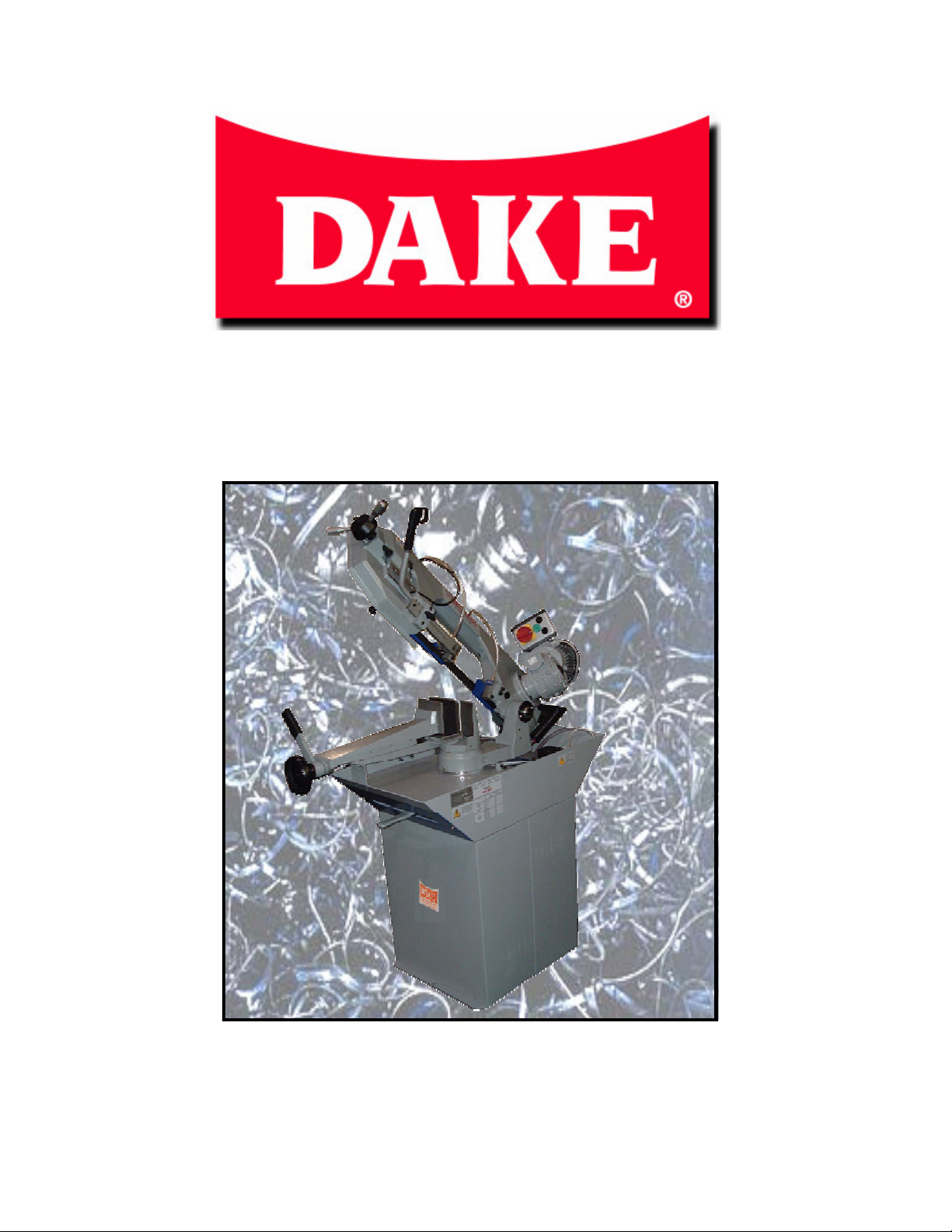
ZIP CUT 28 MITER BANDSAW
Bandsaw Operations Manual
DAKE
724 Robbins Rd
Grand Haven MI. 49417
Phone 800-937-3253 Fax 800-846-3253
www.dakecorp.com
Page 2

Section Page
1. Machine placement / set up / installation: 3
1.1 Base set up 3
1.2 Saw Assembly 3
1.3 Anchoring base 3
1.4 Installing saw to base 4
1.5 Power connections 4
1.6 Accessory installation 4,5
2. Component features, functions and adjustments 5,6,7
3. Safety: 7
4. Machine operation: 8
4.1 Set up 8
4.2 Operation 8
5. Changing the blade: 8,9,10
6. Guide and preset calibrations: 9,10
7. Maintenance and routine adjustments 11
7.1 Maintenance Daily 11
7.2 Weekly Maintenance 11
7.3 Monthly Maintenance 11
7.4 Routine Adjustments: 11
8. Blades: 12
8.1 Simplified selection chart 12
8.2 Blade Break In 12
9. Specifications: 14
10. Drawings: Electrical / Exploded Views / Part Numbers 15-18
11. Trouble Shooting: 19-22
TABLE OF CONTENTS
MACHINE MODEL
SERIAL NUMBER
DATE OF PURCHASE
2
Page 3
MACHINE SET UP / INSTALLATION
1. Machine assembly / set up installation:
1.1 Saw base / pedestal:
1. Remove preassembled base from shipping container. Check for loose parts and
discard container.
1.2 Saw assembly:
1. Carefully remove the saw from the shipping container. Take care not to damage any
components, check for any loosen items. Discard container.
1. Machine Placement:
1.3 Anchoring the machine:
NOTE: Machine must be located away from, congested areas, traffic areas, close
proximity to where others will be working!
Bandsaw should always be positioned so operator can be accessible to all sides and
that there are no trip hazards or liquids present. Keep sides of saw area clear so there is
enough room to feed material into the saw. Keep the back of the saw 32” away from
walls.
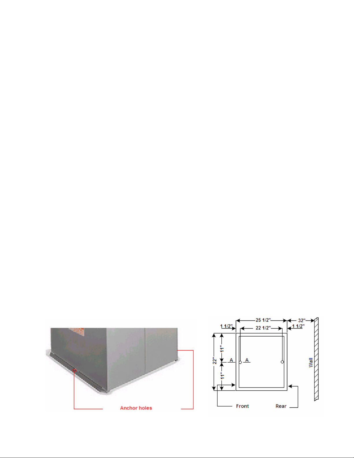
Saw must be anchored on a level hard surface! Machine must be removed from the
pallet. Anchoring of the machine must be done to prevent movement of the unit during
operation. The base is supplied with two mounting holes one on the front and one on the
rear of the saw. (Figure 1) Anchoring must be done in a suitable fashion.
Figure 1 figure 2
3
Page 4
1. Installing machine to base:
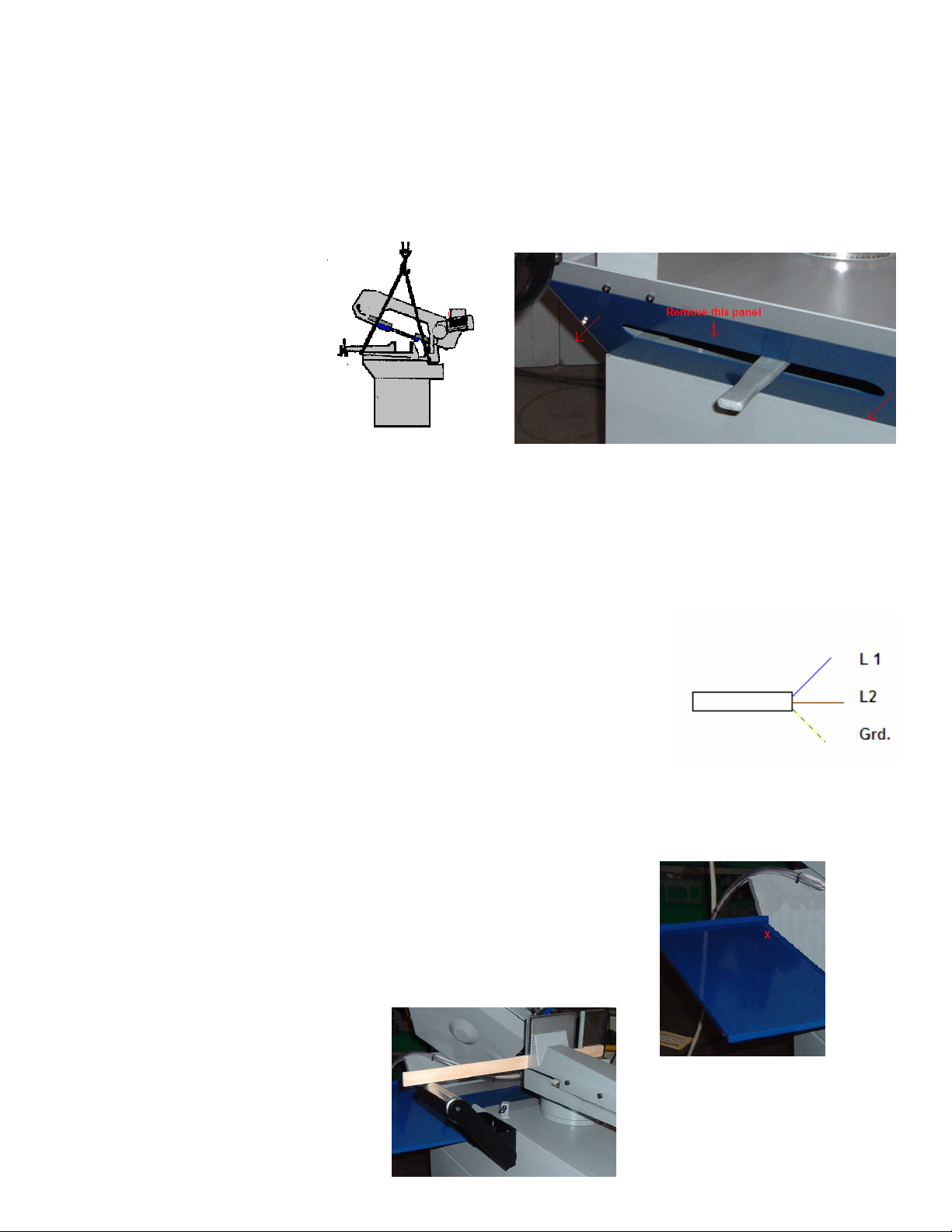
1.4 Carefully strap the saw as shown in drawing figure 3. Lift the saw and set carefully onto the
base that is anchored to the floor. With straps still on the saw remove the front blue access panel.
(Figure 4) With the panel removed and using the 4 supplied bolts, bolt the machine onto the base and
tighten bolts securely.
Replace the access panel.
Figure 3 figure 4
1. Power connections:
NOTE: before connecting power make sure main power is OFF and make sure there are no
damaged parts on the machine, and that all components move freely and are not rubbing,
binding etc.!
1.5 Connection of power to this machine must be done by a qualified electrician. Machine
is supplied with a power cord that can have a plug (20 amp) installed or can be hardwired into a
suitable power source. Minimum 20 amp service is recommended for this machine.
1. Accessory installation:
1.6 Installation of the drip tray, roller support and stock stop can be done at this time.
1. The drip tray is mounted to the left rear of the saw to prevent coolant from dripping onto the
floor while cutting miters. On the back left hand side of the saw (Approx. by the red X see figure
5) is a bolt, remove this bolt. Fit the tray with the folded lip over the saw edge and align the hole
in the lip of the tray with the bolt hole. Install bolt and snug up.
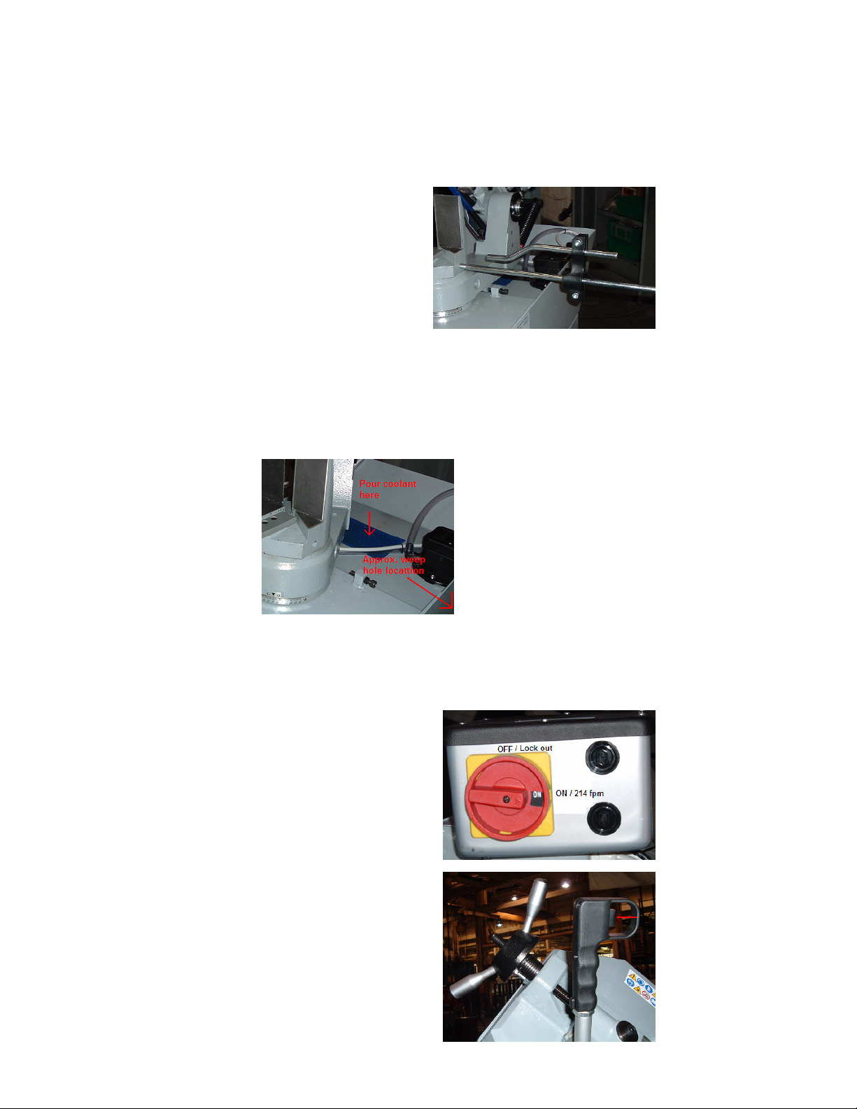
2. Roller assembly is mounted just in front of the drip tray on the
Left hand side of the machine. This roller is bolted to the machine using
The bolts and washers supplied and that are screwed in the saw at the
Mounting point. Remove the bolts and install the roller only figure
tightening the bolts. Using a straight piece of material clamped in the
Vise flat on the table, adjust the roller up to this material and tighten
Bolts. (See figure 6) Check the
Level of the roller both rear and
Front. Both must be at the same
Height.
Figure 5
Figure 6
4
Page 5
3. Stock stop installation can be done at any time. This is used to deadhead your material against
for cutting repeat lengths. This can be removed if not being used. The stock stop screws into the
vise base on the right hand side of the vise. (Figure 7) The stop is measured using a tape or
template from the blade to the face of the stock stop. It is adjusted by loosening the pinch bolts
on the stop block.
Figure 7
4. Add coolant. Mix the coolant as outlined in the instructions furnished with the coolant
concentrate. Usually mixed 10:1. Use only a high quality water soluble coolant. NOTE: Do not
use cutting oils!
Premix the coolant and pour small amounts directly into the blue filter screen on the back of the
saw. (Approx. 3 gallons) Do not over fill because on the right rear side there is a weep hole that
excess coolant will flow out of onto the floor. Slowly add coolant and check in the weep hole
using a small wire or pencil and stop filling when you are about ¼” from the weep hole. (Figure 8)
Figure 8
2. Component features, functions and adjustments:
A. Electrical Box. Off with lock out / on @ 214 fpm.
NOTE: With switch on the motor does not run!
B. Trigger Switch. Dead man style safety switch.
Trigger is pulled to make motor run.
(Both blade and coolant motors)
5
Page 6
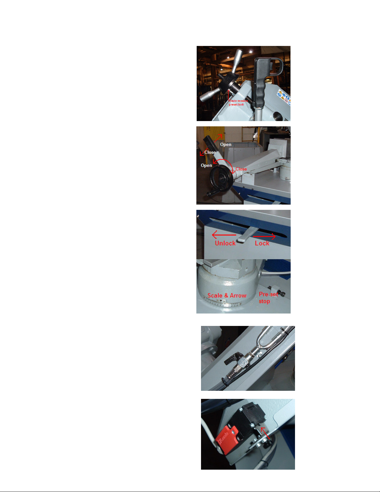
C. Blade tensioning handle. Mechanical
Blade tensioning handle is turned clockwise
To tighten blade; Handle will hit preset bolt
At the proper tension for the blade size.
NOTE: If different size blade is used, length or
Thickness this bolt will need to be re-calibrated
Using a blade pressure gauge to achieve proper
Preset tension.
D. Quick Release Vise. Using the handle wheel
Adjustment of the material can be made by
Opening or closing the vise up to the material.
Once the vise jaws come with-in a 1/16 – 1/8”
Of the material the quick release cam handle
Can be used to open or close the vise to the
Material for fast action.
E. Head Lock Lever. The head lock lever
When released allows the rotation of the
Cutting head up to 60° for mitering. Move
The lever to the left to unlock the head and
Right to lock it at any angle. For angle set
Up align arrow to the angle required on
The scale at the bottom of the rotation
Point of the vise. There is preset
Adjustable stops at 90° (0°) and 60°
These can be calibrated by turning the
Stop bolts in or out to get correct angle.
F. Coolant Flow Control. This valve is located on the
Bandsaw cutting head on the top of the casting
Towards the rear of the saw head. This valve controls
The amount of coolant distributed during cutting.
When adjusting be sure coolant flow is sufficient to
Both guides.
G. Interlock. This interlock is mounted on the rear of
The cutting head and will disable the saw when the
Blade cover is open. This prevent accidental starting
Or running of the machine during blade changes.
6
Page 7

H. Guide Arms. The guide arms are horizontally
Opposed for great rigidity. The outward arm is
Adjustable in and out allowing for close proximity
To the material when cutting different diameters.
By loosen the locking bolt knob the guide will
Slide in and out for the different size materials being
Cut. You always want the guides as close to the
Material as possible. NOTE: When moving this
Arm make sure the arm rail is seated into the way
Fully before tightening locking knob.
I. Throat Filler Plate. This filler plate is bolted to the
V groove in the vise. This filler plate takes up
Room in the V when straight cutting, allowing for
Cutting shorter lengths without the part falling
Under the blades path, and giving a larger support
Area. When miter cutting this filler plate can be
Unbolted and removed to allow cutting of miters
Without damaging the plate.
3. Safety:
NOTE: Do not operate this machine until all adjustments have been made and you have
read the safety instructions!
1. Wear approved safety glasses with side shields..
2. Wear non-slip foot ware. Do not over reach! Keep a safe footing.
3. Wear a dust mask if material being cut is dusty or lets off particles such as fiberglass.
4. Wear hearing protection.
5. Keep guards in place and in good condition. Lock machine out if guards or components are
broken or missing. Replace any worn or broken parts without delay.
6. Make sure the incoming power supply is up to codes and kept in good condition.
7. Always wait until blade has stopped completely before opening covers / doors, reaching into
point of operation or making adjustments.
8. Use good quality blades of the correct tooth configuration for the material being cut and of
the right size. Change blades when needed. If the blades are worn, burnt, cracked, and
missing teeth they must be changed. Dispose of discarded blades properly.
9. Handle blades with care! They can cut, even through gloves.
10. Keep hands away from the blade and parts of material being cut? The parts may be hot and
can burn you.
11. Keep all work clean. Monitor coolant regularly and replenish or change as necessary.
12. Keep area of machine well lit.
13. Keep all visitors and children a safe distance from machine.
14. Anchor the machine to a solid level floor.
15. Do not wear loose clothing, jewelry, neck ties, rings, loose long hair, and gloves.
16. Do not force the work. Too much pressure or hard jabs can cause injury, ruin the blade,
create excessive heat.
17. Do not operate the machine if under the influence of drugs, alcohol, or medications.
18. Do not use machine for purposes that it was not intended for. Do not force the material.
19. Do not leave the machine running unattended. Always turn off machine and wait for it to
stop before walking away.
NOTE: Turn off power and lock out when ever changing or installing the blade
Always use high quality blades of the correct size!
7
Page 8

WARNING: Never let the pull down handle go at the end of the cut. The cutting head is under
spring tension and will return upward rapidly and could cause serious injury. Always keep
hands on the pull down handle.
Always cut with arm extended, never put face over the cutting head return path!
4. Machine operation:
4.1 Set-up
1. Select cutting speed by placing the switch on control box to the ON position. (Paragraph A in
section 2)
2. Set length. Using the stock stop, tape measure or line on the material place the part under
the blade at desired length. (Figure 4)
3. Clamp the material into the vise. Make sure material is supported and level with the cutting
table using the hand wheel run the vise jaw just up to the material leaving approx. 1/16” –
1/8” gap. Move the quick release vise lever down until part is firmly held in place. (Paragraph
D in section2)
4. If miter is required loosen the head lock lever and rotate cutting head to desired angle and
lock in place. NOTE: For some miters the throat filler plate must be removed. Do so before
material is clamped. (Paragraph E , I in section 2)
5. Adjust guide arm distance if needed. You want to maintain close proximity to the material if
possible. (Paragraph H in section 2)
4.2 Operation:
1. With all set up complete, turn the start switch to the ON position making sure you have a
firm footing and a comfortable grasp of the pull down handle, squeeze the trigger to start the
blade. Take note while the blade is running but not in the work of the coolant flow. You want
a steady but not excessive flow from both guides. If flow is not suitable adjust the flow
control valve before continuing. (Paragraph F in section 2)
2. Slowly pull the cutting head down allowing the rotating blade to make light contact with the
material. When contact with material is made increase the pressure and continue with the
cut. When the cut is finished with the blade still running raise the blade up just past the
material and release trigger to stop the blade. Keeping the blade running while raising the
blade prevents the blade from catching the material and damaging the blades teeth.
Continue to lift the head all the way back up keeping control of the cutting heads return rate.
NOTE: Never let go of the pull down handle before it reaches its up most rest position!
NOTE: New blades must be broke in properly for best performance and blade life. See the
blade selection section in this manual for break in and optimum cutting hints.
5. Changing the blade:
Handle blades with caution they are sharp and can cause serious injuries!
1. Turn power off and lock out machine. (Paragraph A in section 2)
8
Page 9

2. Remove four knobs that hold blade cover in place. (Figure 9) Hold onto the cover to
prevent it from falling. Remove the cover and
Set out of your way.
3. With the cover removed, remove blade
Guard from the moveable guide arm and
Set it aside. (Figure 10)
Figure 9
Figure 10
4. Using a pair of heavy gloves that are not prone to snagging, hold the top of the blade
while loosening (counter-clockwise) the blade tension handle, until blade is slackened.
(Paragraph C in section 2)
Slowly and carefully lower the top of the blade downward (off the wheels) in the direction
it will want to go. (Figure 11) While holding the top of the blade and it being laid
downward, push the blade downward out of the guides. (Figure 11) Remove, coil and
discard safely.
Figure 11
5. Install new blade in reverse order. Carefully uncoil the blade. NOTE: Do not toss the
blade on the ground to uncoil. This is a very dangerous and
Damaging practice! Read the instructions on the blade box.
Remove the plastic teeth protection strip from blade if so
Equipped. With blade laid flat insert the blade between the
Guide rollers and push upward until the fully seat into the
Guides and guide pads. Make sure the blade contacts
The upper blade guide. See photo
9
Page 10

With the blade being held in the guides, loop the blade over the drive wheel and front idle
wheels. Apply a slight amount of tension to the blade with the blade tensioning handle,
enough to hold the blade onto the wheels. Check that the blade is still fully in the guides
and push the blade up against the back lips of the wheels. Tighten blade tensioning
handle until it dead heads the preset bolt. (Paragraph C in section2)
NOTE: Before installing the blade check the blade because at times the blade will
reverse it self while uncoiling, make sure teeth are facing the rear of the machine
or in the direction the blade travels. If blade is reversed carefully twist the blade to
reverse the teeth direction.
6. Replace the blade guard; make adjustments so it does not rub on the blade.
7. Replace rear blade cover. Make sure interlock switch in engaged. (Paragraph G in
section 2)
8. Restore power to the machine and jog the blade a few times to make sure the blade is
seated into the guides.
6. Calibrating blade guides and tensioning preset bolt for different size blades.
NOTE: It is recommended that the same size of blade be used as originally equipped. Dake is
not responsible for any of the following changes that may be required for blades of different
specifications.
1. The machine is calibrated for a bi-metal blade that is 97 ½” long, 1” wide and 0.035 thick.
Never use blades that are wider than 1” or narrower than 1”. Damage may occur to guides
and blade.
If a blade is used that is either longer, shorter or of a different thickness re-calibration may
be necessary to the preset bolt or blade guides.
2. Preset tension bolt can be adjusted inward or outward for shorter or longer blades. To
calibrate the bolt should be screw inward to allow installation on the new blade. With the
blade installed is should be tensioned according to the manufactures specifications using
a tension gauge. With proper tension applied adjust the preset bolt out until it dead heads
the tensioning handle. Lock in place with the jam nut. (Paragraph C in section 2)
3. For a blade of a different thickness, thinner or thicker the guide pads may require
adjustment.
Loosen nut C, screw B and set screw D
Widening the distance between pads.
Loosen nuts H, and set screws I and
Rotate the eccentric pins E-G to widen
Clearance between bearings F.
Mount new blade and place the blade
Against pad A, adjust set screw D until
You have approx. 0.010 – 0.015 of
Clearance to blade. Lock screw a in place
with nut C.
Rotate eccentric pins E-G until bearings have a slight drag on the blade then tighten nuts
H and set screws I. Do not place too much drag on these bearings.
10
Page 11

7. Maintenance and routine adjustments.
7.1 Maintenance Daily:
1. Top off coolant as needed.
2. General cleaning of machine. Clean chips and debris from machine.
3. Check condition of the saw blade.
4. Check all guards and interlocks.
7.2 Weekly Maintenance:
1. Clean all chips from coolant filter cover. (Blue cover on top rear of machine)
2. Clean band wheels.
7.3 Monthly Maintenance:
1. Check tightness of band wheel bolts.
2. Check guides for wear debris for adjustment.
3. Check guards and interlocks.
4. Replace coolant. Clean coolant reservoir and pump pick up screen.
NOTE: Gear box is maintenance free.
7.4 Routine Adjustments:
1. If slop develops in vise, tighten vise slide screws.
2. Calibration of guides or preset tensioning bolt. (See 6.1 –3)
3. Head height and depth of cut.
Per photo on the right there are two
Adjusting screws with lock nuts. One
Bolt in the back is for setting max.
Height of the head return. This can
Be set so the head does not go up
As high, if material being cut is
Smaller diameters. The other bolt
In the front limits the depth of cut,
And can be set to prevent cutting
Into the vise casting. Simply loosen
Lock nuts adjust bolts to where you need them and tighten lock nuts down.
4. Angle stop calibration see paragraph E in section 2.
5. If head lock lever is loose and will not tighten head in position remove from access panel
(As you did during mounting of saw to base) set the lever in the tighten position. With the
lever all the way to the right loosen the large clamp bolt on the locking lever casting. Drop
handle down slightly on the shaft and move toward the left a very small amount. (A
couple of teeth on the shaft are sufficient), push the lever back up onto the shaft and
tighten clamp bolt. Reinstall access panel.
11
Page 12

8. Blades:
8.1 Simplified selection chart at right.
1. Rules of thumb for blade selection
Four important numbers to keep in mind are the
Rule of thumb numbers. These numbers are
3, 6, 12 and 24:
Number 3: Represents the minimum
Number of teeth you want working at one
time. If the blade is too coarse for the work,
The teeth can straddle the work; this will strip
Teeth from the blade.
Number 24: The maximum number of teeth you would want in the cut at one time. Too fine a
tooth blade will clog with chips again resulting in stripped teeth.
Number 6 to 12: The ideal number of teeth working at one time.
8.2 Blade breaks in:
1. It is recommended that the blade manufactures break procedure is followed.
Proper blade break-in is as important to good blade life as choosing the right blade. The best
analogy I have heard for blade break-in is the pencil story. If you sharpen a pencil to a nice
sharp point and attempt to write with it, the lead breaks off because it is too sharp to glide
over the paper. If you take the same pencil with the same sharp point and lightly rub it over
the paper you hone or soften the point, resulting in a pencil that can be used for a long period
of time.
The same is true with a bandsaw blade.
When it is new it has very sharp point over
the length of the blade that will tear the
material, chatter and chip or round off the
teeth in a hurry. Breaking in the blade
allows for tips of the teeth to be honed into
a usable tooth that produces good cuts and
longevity.
Blade break-in will vary depending on the
type of material you are cutting. Softer
materials such as carbon steel or aluminum
will require a longer break-in cycle than that of harder materials. Structurals and pipe will
require a longer break-in period because the actual square inches are reduced due to the
interruptions of the material. From the charts listed earlier you can determine if the break-in
will be for softer or harder material
A simplified rule of thumb break-in procedure that applies to most applications:
1. Set blade speed to normal cutting fpm.
12
Page 13

2. Figure out number of square inches the material is, e.g. 4” x 4” solid = 16 sq inches.
3. Decrease your head feed pressure to ½ of normal cutting rate - “soft material” and ¾ of the
normal cutting rate for “hard material”.
4. Start machine cutting. Increase speed slightly when blade has cut distance equal to the width
of the blade.
5. Increase speed again slightly as the blade reaches the halfway point of the cut. Finish the
cut without increasing feed again.
6. Start the next cut with the same feed rate as you ended the last cut. Increase the feed rate
again before reaching the halfway point.
7. Repeat step 7 until the blade has cut the recommended number of square inches determined
from the graph below. The cutting time at this point should be at the recommended cutting time,
but adjust if needed.
Total area required for blade break-in can be figured using this
graph, e.g. 4” x 4” = 16 sq. inches of 1020 mild steel cut at 214 fpm
requires 30 square inches of material to be cut at break-in speeds
(dotted line). Dividing the recommended square inches of material
area needed for break-in by the square inches of material will tell
you how many pieces to cut at the break-in speeds. Approximately
2 pieces will need to be cut at break-in speeds in this example.
Determine cutting speeds and feeds by the chip.
1. Look at the sample chip drawing to determine optimum cutting parameters.
Long spiral-shaped chips indicate ideal cutting.
Very fine or pulverized chips indicate lack of feed
And/ or cutting pressure.
Thick and/ or blue chips indicate overload or the
Blade or too much cutting pressure.
13
Page 14

9. Specifications:
Capacities:
@ 90° 8 ¾” 7 ¾” 10” x 6”
@45° 6 ¼” 6” 10 ¼” x 3 1/8”
@60° 4” 4” 4” x 4”
Horse Power 2 HP max.
Gear Reduction 28:1
Wheel Dia. 11 ½”
Blade Size 97 ½” x 1” x 0.035
Blade Speed 214 fpm
Max. Vise Opening 10 ½”
10. Drawings: Electrical / Exploded Views / Part Numbers
Contactor Part number 301457
14
Page 15

Ref #
Dake Part #
1 010A0009
2 99200002
3 99200003
4 99200004
5 NOT AVAILABLE
6 9920006
7 86005005
8 84320017
9 D80A0011
Ref #
Dake Part #
10 99200010
12 88140020
13 88600000
14 69501000
15 49001003
16 D80A1006
17 99200017
18 99200018
15
Page 16

Ref #
101 99200101
102 99200102
103 99200103
104 99200104
105 99200105
106 86002004
107 AFC10047
108 230B0001
109 AFC40109
Dake Part #
Ref #
111 050B0012
113 99200113
114 99200114
115 AGB80031
116 84310015
117 NOT AVAILABLE
118 99200118
119 9920019
120 99200120
Dake Part #
16
Page 17

Ref # Dake Part #
201 99200201
202 99200202
204 99200204
205 81700035
206 53500112
207 53500128
208 D80C0083
209
210 76200003
Ref # Dake Part #
212 99200212
213 82502082
214 82502082
215 84101054
216 AFC40052
217 AGC40051
218
219
220 99200220
Ref # Dake Part #
221 99200221
222 99200222
223 99200223
224 82505101
225 99100046
226 AFC40144
227 44600001
228 99200228
229 AFC40146
17
Page 18

Ref # Dake Part #
230 99200230
231 86005005
232 84320014
233 81700025
234 44114512
235
236 99200236
237 AF750030
238 99200238
Ref # Dake Part #
239 72212000
240
241
242
243 160C0030
244 100C0005
245 AF750147
246 AF750147
247 AF750146
Ref # Dake Part #
248 AF75B148
249 AF750148
250 84113010
252 AFC40145
18
Page 19

11. Trouble Shooting:
19
Page 20

20
Page 21

21
Page 22

NOTES:
22
 Loading...