

Page 1

DAKE VDL-18
ASSEMBLY AND INSTRUCTIONAL MANUAL
WARNING! Read and understand all instructions and responsibilities before
operating. Failure to follow safety instructions and labels could result in
serious injury.
Dake Corporation Phone: 800.937.3253 www.dakecorp.com
1809 Industrial Park Dr. customerservice@dakecorp.com
Grand Haven, MI 49417
Page 2

Dake Corporation
1809 Industrial Park Dr
Grand Haven, MI 49417
www.dakecorp.com
Table of Contents
DAKE Standard Limited Warranty ..................................................................................................... 3
Finished Machines ............................................................................................................................ 3
Parts .................................................................................................................................................. 3
Sale of Service (Repairs)................................................................................................................... 3
Warranty Process .............................................................................................................................. 3
Warranty Exceptions ......................................................................................................................... 4
Return & Refund Policy ...................................................................................................................... 4
Returns .............................................................................................................................................. 5
Refunds ............................................................................................................................................. 5
Specifications ...................................................................................................................................... 6
Machine Specifications ...................................................................................................................... 6
Safety Warnings .................................................................................................................................. 7
Safety Labels: .................................................................................................................................. 10
Introduction - Assembly of components-Before starting……………………………………………….11-25
Blade install - tracking - tensioning ………………………………………………………………….26-28
Ceramic Guide Adjustment …..……………………………………………………………………….29-33
General Instructions: ....................................................................................................................... 33
Blade Guidepost Adjustment: .......................................................................................................... 34
Table Tilt: ......................................................................................................................................... 34
Fence Assembly Adjustment: .......................................................................................................... 35
Maintenance ...................................................................................................................................... 35
Trouble Shooting: ....................................................................................................................... 36-37
Parts List....................................................................................................................................... 38-57
Parts list & Exploded diagrams …………………………………………………………..…………..38-57
1VDL-18 Wiring Diagram:................................................................................................................ 58
Order Information ............................................................................................................................. 59
Part# VDL-18 2 REV#082020
Page 3

DAKE Standard Limited Warranty
Finished Machines
- Dake warrants to the original purchaser the finished machine manufactured or distributed
by it to be free from defects in material and workmanship under normal use and service
within 1 year (12 months) from the delivery date to the end user.
Parts
- Dake warrants to the original purchaser the component part manufactured or distributed
by it to be free from defects in material and workmanship under normal use and service
within 30 days from the delivery date to the end user.
- The standard limited warranty includes the replacement of the defective component part
at no cost to the end user.
Sale of Service (Repairs)
- Dake warrants to the original purchaser the component part repaired by Dake
Corporation at the manufacturing facility to be free from defects in material and
workmanship under normal use and service within 90 days from the return date to the
end user, as it pertains to the repair work completed.
- The standard limited warranty includes repair of the defective component part, at no cost
to the end user.
Warranty Process
- Subject to the conditions hereinafter set forth, the manufacturer will repair or replace any
portion of the product that proves defective in materials or workmanship. The
manufacturer retains the sole right and option, after inspection, to determine whether to
repair or replace defective equipment, parts or components. The manufacturer will
assume ownership of any defective parts replaced under this warranty.
- All requested warranty claims must be communicated to the distributor or representative
responsible for the sale. Once communication has been initiated, Dake Customer Service
must be contacted for approval:
Part# VDL-18 3 REV#082020
Page 4

• Phone: (800) 937-3253
• Email: customerservice@dakecorp.com
When contacting Dake, please have the following information readily available:
- Model #
- Serial #
- Sales Order #
Purchasers who notify Dake within the warranty period will be issued a Case number and/or a
Return Material Authorization (RMA) number. If the item is to be returned per Dake’s request,
the RMA number must be clearly written on the exterior packaging. Any item shipped to Dake
without an RMA will not be processed.
Warranty Exceptions
The following conditions are not applicable to the standard limited warranty:
(a) Part installation or machine service was not completed by a certified professional,
and is not in accordance with applicable local codes, ordinances, and good trade
practices.
(b) Defects or malfunctions resulting from improper installation or failure to operate or
maintain the unit in accordance with the printed instructions provided.
(c) Defects or malfunctions resulting from abuse, accident, neglect, or damage outside
of prepaid freight terms.
(d) Normal maintenance service or preventative maintenance, and the parts used in
connection with such service.
(e) Units and parts which have been altered or repaired, other than by the manufacturer
or as specifically authorized by the manufacturer.
(f) Alterations made to the machine that were not previously approved by the
manufacturer, or that are used for purposes other than the original design of the
machine.
Return & Refund Policy
- Thank you for purchasing from Dake! If you are not entirely satisfied with your
purchase, we are here to help.
Part# VDL-18 4 REV#082020
Page 5

Returns
- All Dake manufactured / distributed machines, parts and couplings include a 30-day return
option. These policies are valid from the date of final shipment to the end user. To be
eligible for a return, the item must be unused and in the same condition as received. All
requested warranty claims must be communicated to the distributor or representative
responsible for the sale. Once communication has been initiated, Dake Customer Service
must be contacted for approval:
- Phone: (800) 937-3253
- Email: customerservice@dakecorp.com
- Once the return request has been approved by Customer Service, a representative will
supply a Return Material Authorization (RMA) number.
- The returned item must have the provided RMA number clearly marked on the outside
packaging. Any item received without an RMA number clearly visible on the packaging
will not be processed.
- An RMA number can only be provided by the Dake Customer Service team and must
be obtained prior to the return shipment.
Refunds
- Once the item has been received and inspected for damages, a representative will
notify the requestor referencing the provided RMA number. If the return is approved, a
refund will be issued to the original method of payment, less a 20% restocking fee.
- The restocking fee may be waived if an order is placed at the time of return with like-
value merchandise. Transportation costs are the responsibility of the end user and will
not be credited upon return approval.
- Any item that is returned after the initial 30 days or has excessive/obvious use will not
be considered for a full refund.
Part# VDL-18 5 REV#082020
Page 6

Specifications
VDL-18 Bandsaw
Description
Dimensions
Motor Voltage/HP
115/ 230V (prewired 115V)/ 1-3/4HP
Breaker
15 amp for both 115V and 230V
Throat
18 7/32" (463mm)
Table cast iron
20" x 26" (508mm x 660mm)
Front table to center of blade
11" (280mm)
Table tilt
- 6 degrees + 45 degrees
Miter slot
3/8" x 3/4" (9.525mm x 19.05mm)
Table height
38" (965mm)
Fly wheel
Cast iron
Resaw capacity
16" (406.4mm)
Minimum blade length
143 3/4" (3,651mm)
Maximum blade length
145 1/2" (3,695mm)
Maximum blade width
1-1/4" (31.75mm)
Minimum blade width
1/8" (3mm)
Guides
Laguna ceramic
Blade speeds (FPM)
Variable speeds
Low: 100-290
High: 1200-3500
Dust chute diameter (OD)
4" x 2
Height
77 3/4" (1,975mm)
Machine dimensions (W x D) Base
footprint
36 3/16" x 36" (919mm x 915mm)
27" x 19 2/3" (688mmx500mm)
Machine dimensions with mobility kit (W
x D)
Base footprint with mobility kit
43" x 36" (1093mm x 915mm)
37 3/8" x 24 11/32" (949mm x 618mm)
Weight gross
515 lbs (234 kg)
Weight net
480 lbs (218 kg)
Package size (W x D x H)
81 1/2" x 33 7/8" x 30-1/4"
(2070mm x 860mm x 770mm)
Variable Foot Brake
Disk Rotor
Mobility kit
Optional
Industrial work-light
Optional
Machine Specifications
Part# VDL-18 6 REV#082020
Page 7

- In the space provided record the serial number and model number of the machine. This
information is only found on the black Dake tag. If contacting Dake this information must be
provided to assist in identifying the specific machine.
Model No:
Part No:
Serial No:
Date of Purchase:
Safety Warnings
BEFORE USE, ALL SAFTEY INSTRUCTIONS MUST BE READ
- As you know, the vertical bandsaw is a universal saw for contour cutting. Blade selection is
important and by choosing the right blade, you can make most any pattern cutting on most any
material with this machine. However, the most important thing is to realize how to operate it in
a safe and correct way and how to maintain it.
- We have tried to supply you all the information about these. Please be sure to look
through all the contents in this manual so that you may obtain the maximum efficiency
and the longest machine life with minimum expense.
Part# VDL-18 7 REV#082020
Page 8

- The specifications and information in this manual were current at the time this
manual was approved for printing. Dake, whose policy is one of continuous
improvement, reserves the right, however, to change specifications or design at any
time without incurring obligations.
- Always include the part number, model number, and parts description, for parts
orders or correspondence concerning your bandsaw, so we can supply you a
rapidly after-sales service.
▲WARNING
1. Read the operator’s manual carefully. Learn the tools applications and limitations, as
well as the specific potential hazards peculiar to it.
2. Always wear approved safety glasses/face shields while using this machine.
3. Make certain the machine is properly grounded.
4. Before operating the machine, remove tie, rings, watches, other jewelry, and roll up
sleeves above the elbows. Remove all loose clothing and confine long hair. DO NOT
wear gloves when operating.
5. Keep the floor around the machine clean and free of scrap material, oil and grease.
6. Always keep machine guards in place when the machine is in use. If removed for
maintenance purposes, use extreme caution, and replace the guards immediately.
7. DO NOT overreach! Always maintain a balanced stance. Do not fall or lean against
blades or other moving parts.
8. Use only sharp blades. Dull blades are dangerous.
9. Make all machine adjustments or maintenance with the machine unplugged from the
power source.
10. Use the right tool. DO NOT force a tool or attachment to do a job which it was not
designed for.
11. DO NOT make cuts requiring more power than is available on the machine.
12. Replace warning labels if they become obscured or removed.
13. Make certain the motor switch is in the OFF position before connecting the machine to
power.
14. Give your work undivided attention. Looking around, carrying on a conversation. And
“horse-play” is careless acts that can result in serious injury.
Part# VDL-18 8 REV#082020
Page 9

15. Make a habit of checking to see that keys and adjusting wrenches are removed before
▲ WARNING
All electrical connections must be done by a qualified electrician. Failure to comply
may cause serious injury!
All adjustment or repairs must be done with the machine disconnected from the power
source. Failure to comply may result in serious injury!
turning on the machine.
16. Keep visitors a safe distance from the work area.
17. Use recommended accessories; improper accessories may be hazardous.
18. Never place hands directly in line with the saw blade.
19. Always use push sticks when cutting small material.
20. Raise or lower the blade guide only when the machine has been turned off and the blade
has stopped moving.
21. Read and understand warnings posted on the machine.
22. DO NOT use attachments for any other purpose than for what they were designed for.
Failure to comply with all these warnings could lead to serious injury.
This is the safety alert symbol.
- When you see this symbol on your press be alert to the potential for personal injury.
Part# VDL-18 9 REV#082020
Page 10

Safety Labels:
Label Part # 84605 Label Part # 84395 Label Part # 84605
Label Part # 84604 Label Part # 82199
Part# VDL-18 10 REV#082020
Page 11

This bandsaw is designed to give you years of safe service. Read this owner’s
Introduction to Bandsaws.
manual in its entirety before assembly or use.
The bandsaw is generally defined as a saw blade in the form of an endless steel band
that rotates around two or more wheels. This blade is a continuous metal band with
teeth on one side. As the wheels rotate, so does the band, which creates the
continuous sawing action.
Because the direction of the blade is always downward toward the table, there is little
danger (except for special cuts) that the material will be thrown back at the operator,
which is called a kickback.
The unique feature of the bandsaw is that the work piece can be rotated around the
blade creating a curve. It is the tool most often used when curves have to be cut in
Part# VDL-18 11 REV#082020
Page 12

wood or metal.
What you will receive with your Bandsaw.
Because the bandsaw blade is fairly thin, it can cut thick stock with a minimum of
horsepower. For this reason, the bandsaw is often the machine of choice.
Fence
Fence parts
Part# VDL-18 12 REV#082020
Page 13

Fence guide bar
Table ratchet handles & washers Rubber feet and hardware
Fence stop
Table
Part# VDL-18 13 REV#082020
Fence guide bar attachment parts
T bar
Page 14

Note: The mobility kit and light are optional.
1. Tension indicator window
10. Rip fence assembly
2. Switch
11. Dust port 4”
3. Motor
12. Quick-release blade tension lever
4. Frame
13. Blade tracking knob
5. Blade tension handle
14. Optional mobility kit
6. Blade tracking window
15. 110v power socket
7. Cast iron table
16. Blade guide shaft lock
8. Blade guide adjustment hand wheel
17. Flywheel
9. Blade guide
18. Brake foot pedal
Parts of the Bandsaw.
The bandsaw has many parts. The major parts are discussed in this manual. If you are not familiar
with the bandsaw, take the time to read this section and become familiar with the machine.
Part# VDL-18 14 REV#082020
Page 15

4. Frame.
1.
Tension indicator
Tension indicators are designed to indicate the compression of a
spring. As a rule, the greater the spring compression, the
greater the tension on the blade. The tension scale does not
register until the blade is relatively taut and is located on the
inside of the body of the bandsaw. The tension scale is a
general reference and not a rule. The tension indicator is visible
with the upper door closed by looking through the tension
indicator window.
2.
Switch.
To start the machine press the "I" button on the start stop
switch. To shut off the machine press the "O" on the start stop
switch. When the safety switch is pressed it stops the power to
the motor. To reset it, twist and it will pop out and allow power to
be supplied to the motor.
3.
Motor.
The bandsaw is supplied with a 120V motor. It drives the lower
flywheel through a drive belt.
Emergency stop button
Start / Stop buttons
The frame of the bandsaw is a U-shaped frame, which houses all the parts of the
machine. This is the heart of the bandsaw and must be very rigid, as it takes the
strain of the blade being tensioned.
5. Blade tension handle.
The blade tension handle moves the blade tension and tilt assembly vertically. The
vertical action compresses a spring that ensures that the blade tension is constant
and will not change dramatically as the blade length increases due to the heat
generated by the cutting action.
Part# VDL-18 15 REV#082020
6. Blade tracking window.
There is a blade tracking window on the side of the frame that allows the edge of
the upper flywheel to be viewed. This allows the tracking of the blade to be
achieved with the door closed.
7. Cast iron table.
The table supports the work piece and can tilt (-6 degrees to +45 degrees) to produce
cuts at various angles. It has a groove to the right-hand side of the blade, which is
used to guide the miter gauge. In the center there is a table insert which the blade
passes through. Should the blade wander off center, this table insert will protect the
Page 16

blade from damage, as it is soft and should not damage the blade. The table also
supports the adjustable fence, which is used for parallel cuts. There is a nut and bolt
that joins both sides of the table and stops the table from warping. The nut and bolt
must always be fitted in the table and only removed when removing or fitting a blade.
8. Blade guide adjustment hand wheel.
The upper blade guides are attached to the blade guide shaft. The shaft is vertically
adjustable with a hand wheel. The guides should be adjusted so the guides are just
above the wood being cut. This gives the blade maximum stability and is also the
safest way to operate the bandsaw.
9. Blade guides.
There are two sets of blade guides, one above and one below the table. The function
of the guides is to give the blade stability and ensure that the blade movement
left/right, forward/back is kept to a minimum. The guides above the table are fitted to a
shaft that has vertical adjustment. The upper guides are adjustable so that the guides
are held just above the job being cut. This gives the blade the maximum amount of
stability and also keeps the amount of blade that is exposed to a minimum. The
guides have ceramic inserts that can be adjusted for almost zero clearance.
10. Rip fence assembly.
The rip fence assembly consists of a guide rail, cast knuckle, fence attachment
casting, rule and a high-low fence. The guide rail is attached to the table side. It guides
the fence assembly across the table. The cast knuckle slides on the guide rail and is
lockable in any position to suit the width of cut. The fence attachment casting is
attached to the cast knuckle with three screws that when loosened allow the fence to
be adjusted for drift. The fence is attached to the fence attachment casting with two
studded knobs that allow the fence to be adjusted laterally across the table to suit the
job being cut. The fence can be fitted in the low position or the vertical (7 1/4" height)
position.
There is a rule that is fitted to the side of the table and can be used as a quick guide
on the distance that the fence is from the blade. The Fence Stop can be used for non
through cuts and can be set on any length of the fence with the quick release handle.”
Note. The rule will have to be adjusted each time the fence is adjusted for drift, as this will
change the distance the fence is from the blade
11. Dust ports 4".
The bandsaw produces a lot of sawdust, so extraction is very important. This is
achieved by connecting a 4" dust extraction hoses with a minimum capacity of 1,000
CFM to the two dust ports located at the back of the machine. The stronger the suction
Part# VDL-18 16 REV#082020
Page 17

from the dust collector, the better for you and the machine.
12. Quick-release blade tension lever.
There is a quick-release tension lever at the back of the bandsaw. The lever is a
convenient way of quickly releasing the tension on the blade and speeds up blade
change dramatically.
13.Blade-tracking knob.
The blade-tracking knob is located at the back of the bandsaw and is used to adjust the blade
tracking. The knob must be locked once the adjustment is completed
14. Optional mobility kit.
The optional mobility kit is fitted to the base of
the bandsaw and consists of two fixed wheels at
the front of the bandsaw and a swivel wheel at
the back of the band saw. The swivel wheel is
activated and deactivated with a foot lever. With
the swivel wheel deactivated, the bandsaw sits on
two rubber feet.
15. Optional light.
The optional light is fitted with four screws through
pre-drilled holes at the top of the bandsaw.
The bandsaw is provided with a 120V socket that
the light can be connected to.
16. Blade guide shaft lock
The upper blade guide is fixed to the blade guide shaft, which is vertically adjustable. Once the
guides have been adjusted vertically; the shaft is locked in position with the lock knob
17. Flywheel.
The blade is suspended over two wheels that are covered with rubber called a "tire". The tire
cushions the blade and protects the teeth from coming in contact with the metal of the
flywheel. The lower wheel is the drive wheel and is attached to the motor with a rubber drive
belt. The lower flywheel powers the blade and pulls the blade down through the work piece.
The top wheel has two functions. One function is to balance or track the blade on the wheels,
and the second one is to tension the blade. Both functions are adjustable.
Part# VDL-18 17 REV#082020
Page 18

18. Brake.
Assembly and set up.
Assembling the rubber feet.
The bandsaw is provided with a brake that is operated by
applying the foot pedal. When the foot pedal is applied, the
power is interrupted from the motor and the flywheel is slowed
by the disc brake.
19.Guards
When running, the blade can be very dangerous, and the
amount of blade that is exposed must be kept to a minimum.
Disc brake on flywheel
The machine is supplied with a number of guards, all of which MUST be installed and used
while the machine is running. There is a guard that is attached to the lower door and is
adjustable vertically once the door is closed. There is a guard on the guide vertical adjustment
shaft
20. Blade tilt and tension mechanism.
The upper wheel is attached to the tilt and tension mechanism. This mechanism adjusts the
wheel so that the bandsaw blade can be adjusted for blade tracking. This is achieved by a
screwed handle at the back of the machine that pushes on the mechanism and adjusts the
axis of the wheel so that it runs true with the lower wheel. The second function is to tension the
blade, which is achieved by adjusting the upper flywheel vertically. A handle is located below
upper flywheel and, when rotated, will move the wheel up or down. The machine has a quickacting blade release mechanism that is located at the back of the machine and will remove the
tension from the blade to speed the removal and fitting of blades. The mechanism has a
spring, which helps to keep the tension constant as the blade expands and contracts with the
heat generated by the cutting action.
21. Electrical connection.
The bandsaw is provided with a cord and a 120v plug.
Part# VDL-18 18 REV#082020
Page 19
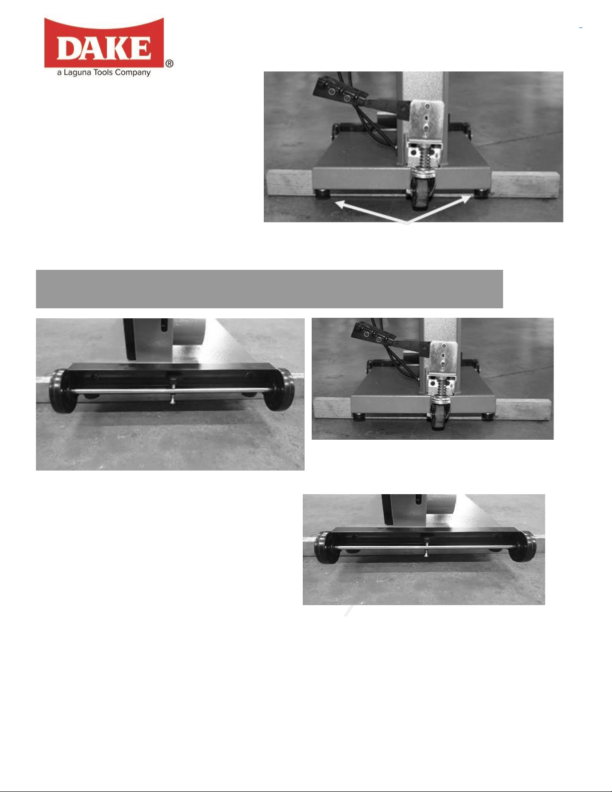
Rear swivel wheel
Front wheels Locking screw
Bandsaw supported on wooden block
Method 1.
Assembling the optional mobility kit
Fit the rubber feet to the bandsaw
prior to removing it from the
packaging.
Method 2.
1.Support the bandsaw on
wooden blocks.
2.Assemble the rubber feet with
the hardware provide both at front and Rubber feet
back of the bandsaw.
1.
Support the bandsaw on wooden blocks.
2.
Fit the swivel assembly to the back
of the bandsaw with the provided
bolts.
3.
Fit the front wheels to the front of the
bandsaw with the bolts provided and
remove the two rubber feet that are
close to the front wheels.
Note. Never operate the bandsaw with
the mobility kit engaged or the front wheel
assembly locking screw engaged.
Part# VDL-18 19 REV#082020
Page 20

.
Trunion clamp stud
Tilt stop bolt
Fitting the table.
It is possible to fit the table to the bandsaw with one person but far easier if you have two people, one to lift
the table and one to guide the trunion clamp studs
Tilt blanking disc Table tilt hole
Tilt stop bolt Tilt blanking disc
The table has a reference stop bolt that is used to quickly align the table after tilting.
The stop bolt hits the tilt-blanking disc when it is positioned over the table tilt hole.
When the tilt blanking disc is moved away from the hole, it allows the tilt stop bolt to
pass through the table tilt hole, and the table can be moved to the maximum amount
of tilt (-6 degrees).
Part# VDL-18 20 REV#082020
Page 21

Table mounted to the bandsaw
Trunion clamp stud
Ratchet handle
With the table fitted to the trunions, assemble the two ratchet handles and flat washers.
How to adjust the table for square to the blade. This will be detailed later in the manual.
Table rule with fixings
Table with rule mounted
Attach the rule to the table with the hardware supplied. Do not
fully tighten the bolts, as the position of the rule will have to be
adjusted to suit the blade, which will be detailed later in the
manual.
Rule adjustment slot
Part# VDL-18 21 REV#082020
Page 22

1. Fit the fence bar to the table with the screws and spacers supplied.
Note. The distance between the fixing holes and the end of the bar is not symmetrical, and
the end that has the longest distance must be at the back of the bandsaw (closest to the
column).
2. Slide the fence support onto the fence bar and fit the fence support clamp screw.
3. Slide the fence onto the clamping strip.
4. Lift the fence just clear of the table and secure it in position with the clamping screws.
Spacer
Fence bar
Fence support
Fence support
Fence support lock knob
Lock knob
Fitting the fence.
Fence in low position Fence clamped in low position
Part# VDL-18 22 REV#082020
Page 23
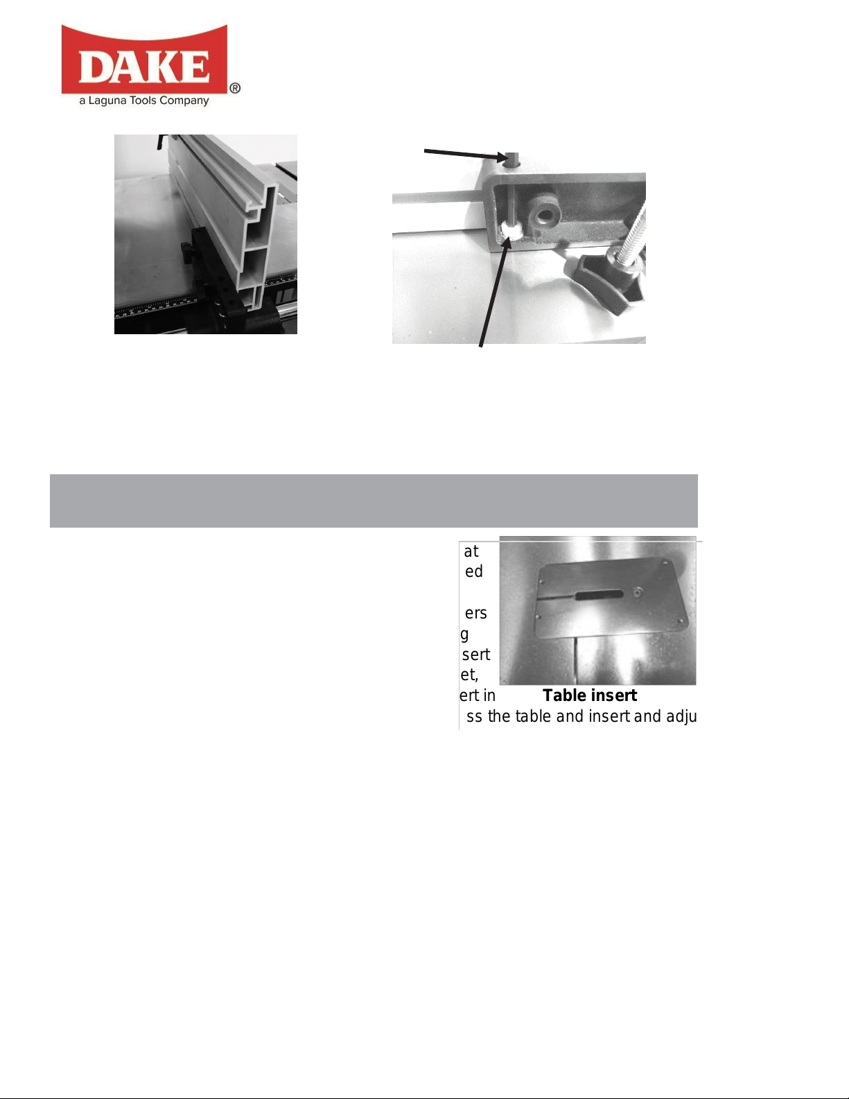
The fence support and the fence are held off the table with a nylon-support Allen
Fence in high position
Allen key
Support Allen screw
Fitting the table insert and Fence Stopper
screw. This screw ensures that the fence and the fence support do not damage the
table. The screw is adjustable to compensate for wear.
The machine is supplied with a removable table insert that
is held in position with a screw. The table insert is removed
when blades are removed or fitted to the machine. The
insert is made of soft aluminum so that if the blade wanders
and contacts the insert, there is less chance of damaging
the blade. Adjusting screws are provided to adjust the insert
vertically level with the table. The insert comes factory set,
but should adjustment become necessary, place the insert in Table insert
the table with the screw fitted. Place a straight edge across the table and insert and adjust the screws
so that the table insert is level with the top of the table.
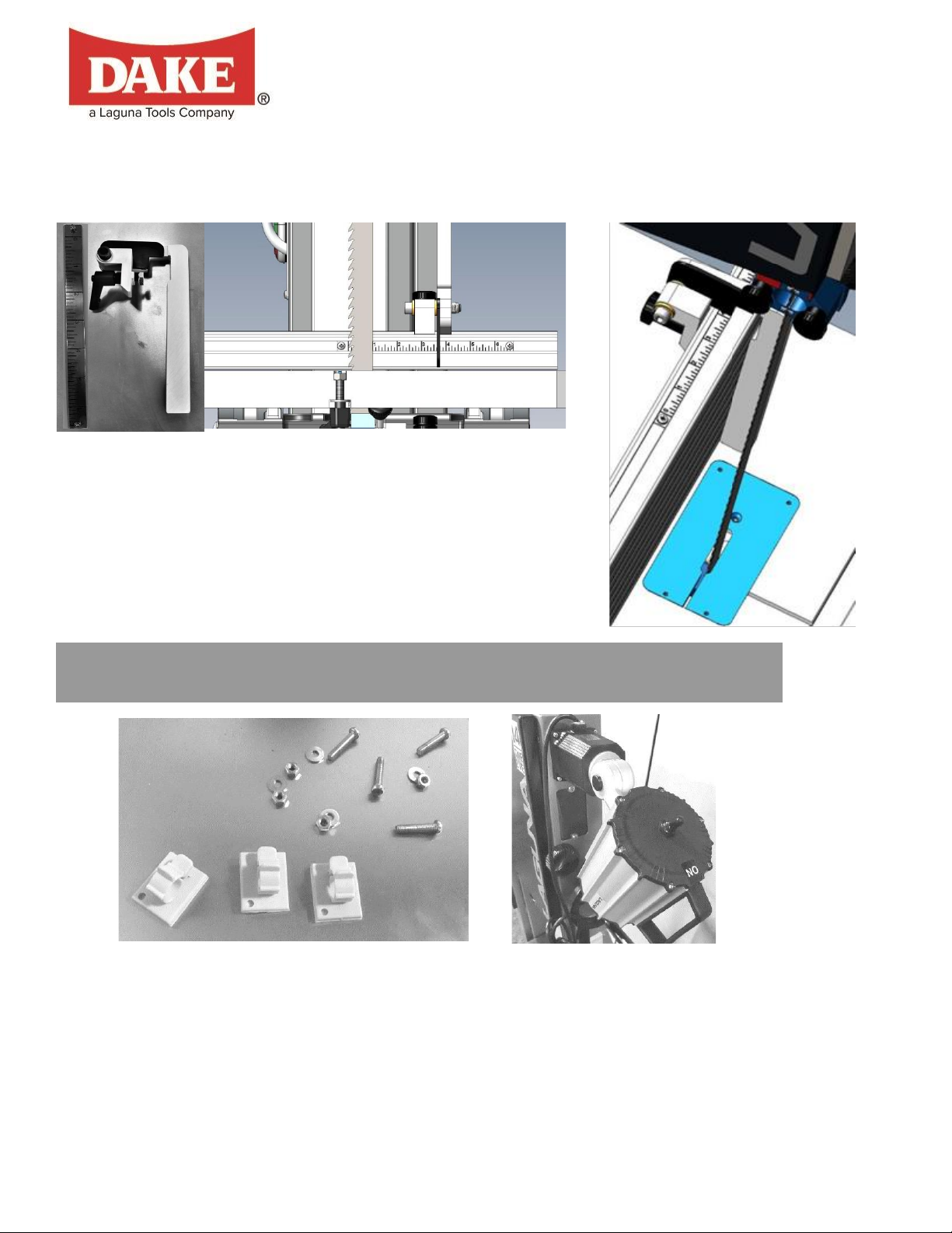
Fitting the Fence Stop
The fence stopper can be used to control the length of cut for non through cuts. To set the stop in
place, the scale should be attached into the T-slot on top of the fence when it is on the vertical
position. The “0” on the scale should be adjusted and set to be align up to the front tip of the blade.
Then refer to the scale, slide the fence stopper to the desired cutting length behind the front tip of the
blade as shown in the scale, then fix the fence stopper in place by tightening down the quick release
handle.
Part# VDL-18 23 REV#082020
Page 24
Fixing screws and cable clips Light fitted in position
Fitting the optional light.
Part# VDL-18 24 REV#082020
Page 25

Suggested cable route
Light plugged into
socket
The light is fitted to the top of the bandsaw as shown. The light is supplied with a plug 120V. The
Before starting the bandsaw.
cable must be held in position with the clips provided and positioned so that the cable is safe and will
not in any way come close to the blade or cabinet door. Above is the suggested cable route. Use the
sticky cable clamps to secure the cable along the top of the bandsaw. Ensure that the cable is not
over the vertical shaft hole, as it could be damaged when the shaft exits the hole.
Read and understand the instruction manual before operating the saw.
1.
If you are still not thoroughly familiar with the operation of the bandsaw, get
advice from a qualified person.
2.
Make sure the machine is properly grounded and that the wiring codes are followed.
3.
Do not operate the bandsaw while under the influence of drugs, alcohol or
medicine or if tired.
4.
Always wear eye protection, safety glasses or a safety shield, and hearing protection.
5.
Wear a dust mask; long-term exposure to the fine dust created by the
bandsaw is not healthy.
6.
Remove your tie, rings, watch and all jewelry. Roll up your sleeves; you do
not want anything to get caught in the saw.
7.
Make sure that the guards are in place and use them at all times. The guards
protect you from coming in contact with the blade.
8.
Make sure that the saw blade teeth point downward toward the table.
9.
Adjust the upper blade guard so that it is just clearing the material being cut.
10.
Make sure that the blade has been properly tensioned and tracked.
11.
Stop the machine before removing the scrap piece from the table.
12.
Always keep your hands and fingers away from the blade.
Part# VDL-18 25 REV#082020
Page 26

13.
A lot of people do not like to change the blades and go to great lengths to avoid doing it. To
use the bandsaw to its greatest advantage, you will have to use the appropriate blade and
track it quickly. This is a habit that can be easily developed. If you use a step-by-step method
of tracking and tensioning, the procedure should only take a minute or two. Be careful when
using blades, especially wide ones. Always use gloves and safety glasses.
Clamp screw
Throat plate
Table split clamp screw
Table split clamp slot
Blade in table split
Plastic blanking block
Make sure that you use the proper size and type of blade.
14.
Hold the work piece firmly against the table. Do not attempt to saw stock that
does not have a flat surface facing down, unless a suitable support is used.
15.
Use a push stick at the end of a cut. This is the most dangerous time because
the cut is complete, and the blade is exposed. Push sticks are commercially
available.
16.
Hold the wood firmly and feed it into the blade at a moderate speed.
17.
Turn off the machine if you must back the material out of an uncompleted or
jammed cut.
Disconnect the power from
the bandsaw.
1.
Remove the throat plate
by removing the clamp
screw.
Part# VDL-18 26 REV#082020
Page 27

2.
Tracking the blade.
Remove the table split clamp
ratchet handle.
3.
Remove the plastic blanking plate.
4.
Adjust the side guide and back guide out as far as they will go (both upper and lower guides).
This will ensure that they do not interfere with the blade while you are installing, tracking and
tensioning the blade.
5.
Uncoil the blade. Remember to use gloves and safety glasses. The blade may have dirt or oil
on it, so use a clean rag to clean the blade by pulling rearwards so that the cloth does not hook
on the teeth
6.
Inspect the teeth and the general condition of the blade. If the teeth are pointing in the wrong
direction when you hold the blade up to the machine, you will have to turn it inside out. To do
this, hold the blade with both hands and rotate.
7.
Slide the blade through the table split.
8.
Open the blade guard door. Slide the blade over the top flywheel and feed through the slot at
the side of the vertical column. Then feed the blade into the blade guard slot and close the
blade guard door.
9.
Deactivate the quick action blade tension lever and rotate the blade tension wheel so that the
blade can fit over the lower flywheel.
10.
Activate the quick action blade tension lever.
11.
Apply light tension to the blade with the blade tension wheel.
1.
To track the blade, start rotating the wheels by hand in the normal direction. As you do this,
watch the blade to determine where the blade wants to track. If the blade is tracking too far
forward or backward, make small adjustments with the tracking adjustment knob located at the
back of the bandsaw while still rotating the wheel. Once the blade is tracking in the correct
position, fully tension the blade and re-track. Lock the tracking adjustment handle.
Note: The blade must be fully tensioned for final tracking.
Note: Never track the blade with the saw running.
Part# VDL-18 27 REV#082020
Page 28

Lock knob
Tensioning the blade.
Blade guard door
Tracking window
Tracking knob Blade in column slot
Blade tension wheel
1.Deactivate the quick action blade tension lever and
rotate the blade tension wheel so that the blade can fit
over the lower flywheel.
2. Activate the quick action blade tension lever.
3. Apply light tension to the blade with the blade tension
wheel.
4.The scale inside the top half door of the bandsaw is
a good reference to use determining what tensions are
good based off the width of the blades for many
applications Quick action tension lever (activated)
.
Blade tension indicator
.
Part# VDL-18 28 REV#082020
Page 29

Introduction.
Welcome to a new era in bandsawing. You have purchased a bandsaw with a revolutionary blade
guide system that is designed to give you years of safe, high-quality bandsawing. Most blade guides
are designed to support the blade on the sides and either above or below the side guides at the back
of the blade. This can allow the blade to twist as pressure from the material being cut pushes against
the back-blade guide. The Ceramic Guide eliminates this by supporting the blade above and below
the back blade guide, giving the blade unsurpassed stability. The Ceramic Guide also incorporates
patented ceramic as the blade support material. The advantage of this material is its ability to resist
wear, and with care it should give years of safe service.
Please read the following notes as they will assist you in getting the optimum performance
from your ceramic guide system.
As with the roller guide systems, the ceramic guide system will damage your blade if it is not adjusted
correctly. The guide blocks must not come in contact with the teeth of the blade. It is advisable to run
the blade by hand with the guide blocks completely clear of the blade, and only when you are
completely sure that the blade is running consistently in the correct position, you may then adjust the
surround guide blocks as detailed in this manual.
Note on using the ceramic guide system.
1.
When fitting a blade to your bandsaw, adjust the guide blocks as detailed later and run the
blade by hand through the guide blocks for at least two complete revolutions.
2.
The weld on a new blade may not be perfectly aligned, and the misalignment could hit the
ceramic blocks (side and back), causing damage to the blocks or the blade. If the blade has a
bad weld, return it to your blade supplier or side dress and file the back of the blade as needed.
3.
The back blade guide is manufactured from ceramic, so as the blade pushes against it, friction
between the blade and the ceramic occurs. This action generates a certain amount of sparks.
This is normal and will become less with time as the back of the blade guide smoothes out the
back of the blade.
4.
The back blade guide will slowly form a small grove as the blade is used (this is normal). It is
recommended that for approximately every 8 hours of use, the guide be rotated 15 degrees.
Part# VDL-18 29 REV#082020
Page 30

This will ensure that the groove does not become too deep and will greatly extend the life of
your guide.
5.
The ceramic guide system can be used with 1/8” to 1-1/4” blades.
6.
The ceramic guide system uses ceramic to support and guide the blade. This has
many advantages (very poor conductor of heat, very resistant to wear, etc.). The
disadvantage is that it is very brittle, so the guides must never be dropped, exposed
to hard knocks, hit with hard objects or used with badly welded blades. Any of the
above actions may cause the ceramic to chip or break and will detract from the
performance of the ceramic guide system. Any mistreatment of the guide system
will render the warranty void.
7.
The side guide blocks must be tightened before running the machine to avoid
jamming the blade and damaging the machine and/or guide blocks.
8.
When cutting gummy material, the blade can become covered with resin. You will
find that the surround guide system ceramic blocks remove the resin as the blade is
moved through the guide blocks and keep that part of the blade clean. For this
reason, it is recommended that the blocks be adjusted as close to the gullet as
possible, but the teeth must not come in contact with the blocks, as they will become
damaged. Although the guide blocks clean the blade, some materials will still gum
the blade and the resin will have to be removed with solvent.
Side guide clamp screw
The blade should run through the
center of the rear blade guide, and the
side guides should be parallel with the
blade. If they have been moved out of
adjustment, adjust as follows:
Top Upper Side Guides Parallel Adjustment.
Loosen the side guides and move out as far as
possible. Loosen the guide assembly and
move back away from the blade.
Move the back blade guide forward so it just
touches the back of the blade and lock in
position.
Back guide clamp screw
Part# VDL-18 30 REV#082020
Page 31

Loosen the guide clamp screw that allows the
side guides to move forward and back. Adjust
so that the ceramic blocks are just behind the
gullet of the teeth and are parallel to the blade.
Retighten the clamp screws.
Gently push one side guide so that it touches
the blade and lock it in position. Bring the other
guide toward the blade so that there is minimal
clearance between the blade and the guide. You
can put a thin piece of paper to put between the
blade and the guide to obtain the correct. Back guide touching back of the blade
clearance until you gain experience. Tighten the
clamp screws and remove the paper. Rotate the
blade by hand, ensuring that the weld of the
blade does not hit the ceramic blocks, as this
will cause damage.
Lower blade guide
The lower blade guides have two locking screws
that, when released, allow the guide assembly to
be moved forward and back. Rotate the blade by
hand and ensure that it is tracking consistently
in the correct position
Loosen the side guides and move out from the
blade. Loosen the two clamp screws that allow
the guide assembly to move forward and back.
Adjust it so that the ceramic blocks are just
behind the gullet of the blade and retighten the
clamp screws.
Place a dollar bill or piece of paper of similar thickness
between the guide blocks and the blade. Gently bring both side
guides toward the blade so that slight pressure is exerted
on the blade. Tighten the clamp screws and remove the
paper.
Rotate the blade by hand, ensuring that the weld of the
blade does not hit the ceramic block
Part# VDL-18 31 REV#082020
Page 32

Loosen the rear guide clamp screw and push
the guide forward so that it just touches the
back of the blade. Tighten the guide in position.
Rotate the blade by hand and check to see that the
back of the blade does not hit the blade guide with a
bad weld..
Note: You will probably find that the guides can be
adjusted more easily by tilting the table to 45
degrees.
Note: Rotate the back guide by approximately 15
degrees after every 8 hours of use. This will greatly
extend the life of the back-blade guide, as it will
even out the wear
Before you cut any metal or wood, read the safety
rules at the front of this manual
Table tilted 45 degree
Part# VDL-18 32 REV#082020
Page 33

General Instructions:
Below are some basic instruction to properly operate the VDL-18 bandsaw machine.
1. Make sure the blade is properly adjusted for tension and tracking.
2. Adjust blade guide assembly so that the guide guides are just above the workpiece (about
3/16”) allowing minimum exposure to the blade.
3. If using the fence, move it into position and lock it to the guide rail. If you are using the miter
gauge for a crosscut, the fence should be moved safely out of the way.
4. Turn the machine on and wait a few seconds for the machine to fully get up to speed.
5. Place the straightest edge of the workpiece against the fence and push the workpiece slowly
into the blade. Do not force the workpiece into the blade. Let the blade do the work.
NOTE: (DO NOT over feed that bandsaw blade. This will reduce blade life and have a greater
chance of breaking the blade).
6. When cutting long stock, the operator should use roller stands, support tables, or an assistant
to help stabilize the workpiece.
7. When cutting at an angle with a tilted table, provide a guide against which the material being
cut can rest. Freehand cutting at an angle can result in injury, and maintaining an accurate cut
is difficult.
9. Deactivate the quick action blade tension lever and rotate the blade tension wheel so that the
blade can fit over the lower flywheel.
10. Activate the quick action blade tension lever.
11. Apply light tension to the blade with the blade tension wheel.
12.The scale inside the top half door of the bandsaw is a good reference to use determining what
tensions are good based off the width of the blades for many applications.
High to Low Setting & FPM setting:
- First will explain the procedure to change the VDL-18 from high gear to low gear or vice versa.
The same procedure applies both ways.
Disconnect the machine from the power source before making any adjustments.
1. Turn the machine off and unplug from the power source.
NOTE: (The motor MUST BE OFF before going to the next step)
2. Once the motor is completely off, slide the lever to the desired high to low setting. You
may run into situations where the lever does not fully go into low or high. If so, carefully
Part# VDL-18 33 REV#082020
Page 34

rotate the blade while trying to put the motor into gear. The lever will fully go into to
Blade Speed Ranges (FPM)
High Gear Range
1200 – 3500 FPM
Low Gear Range
100 – 290 FPM
gear.
- Below is the procedure to change the FPMs of the bandsaw (SAW ON, AND RUNNING).
-
1. To change to the desired RPM on the bandsaw, the bandsaw MUST be on and the
blade rotating in the required gear prior changing the speed.
2. Locate the motor locking level located on the back side if the bandsaw near the bottom
by the motor. Loosen the lever handle.
3. The adjuster hand wheel located on the bottom right of the bandsaw adjusts the blade
speed. referencing to the dial located on the back of the motor.
4. Slowly rotate the handwheel CW to increase the blade speed, or CCW to decrease the
blade speed.
5. Tighten the motor locking lever back in place immediately.
USE CAUTION: Never start the VDL-18 bandsaw with any slack in the drive belt. Doing so
can cause machine damage as the belt is forced to pull through the slack.
Blade Guidepost Adjustment:
- The following steps are to properly adjust the Blade Guidepost height on the VDL-18 Bandsaw.
1. Locate the guidepost locking screw located on the rear top half go the bandsaw. To make
any adjustments, loosen the locking screw to allow the blade guidepost to freely move
horizontally.
2. The hand wheel located above the blade guidepost on the side of the machine adjusts the
horizontal movement of the guidepost.
NOTE: (Maintain a clearance of 3/16 inch between the blade guidepost and the
workpiece to allow minimum exposed blade to prevent injury).
3. After correctly adjusting the height of the blade guidepost, ALWAYS tighten the guidepost
screw for the guide will stay in the desired position.
Table Tilt:
- The following steps are to properly adjust the Table Tilt angle on the VDL-18 Bandsaw.
1. For tilting the table to right (max. 45º), you have to loosen the two ratchet handles, then tilt
the table to your desired angle.
Part# VDL-18 34 REV#082020
Page 35

2. For tilting the table to left (max. -6º), the table has a reference stop bolt that is used to
quickly align the table after tilting. The stop bolt hits the tilt-blanking disc when it is
positioned over the table tilt hole. When the tilt blanking disc is moved away from the hole,
it allows the tilt stop bolt to pass through the table tilt hole, and the table can be moved to
the maximum amount of tilt (-6 degrees).
Tilt stop bolt Tilt blanking disk
Tilt blanking disc Table tilt hole
Fence Assembly Adjustment:
- The following steps are to properly adjust the Fence Assembly Adjustment on the VDL-18
Bandsaw. This will change the accuracy length cut of the workpiece. Check the clearance
between the table and the fence. The fence should not rub against the table surface but be
slightly above it. This gap should be the same at the front of the table as it is at the rear.
1. Loosen the fence locking wheel located on the fence assembly.
2. The fence is now free to move vertically along the worktable.
3. Once in the desired spot, lock the fence in place by tightening the locking screw.
Maintenance
Before performing any maintenance to the machine, make sure to unplug the cord from
the power source before cleaning.
- Maintain bearing guides clean and free of build-up.
- Check that the cleaning brush over the band wheel is working properly and remove any
deposits from the band wheels to avoid vibration and blade breakage.
- The table surface should be always kept clean and free of rust for best results. talcum powder
applied with a blackboard eraser rubbed in vigorously once a week; this will fill casting pores
and form a moisture barrier. This method provides a tabletop that is slick and allows rust rings
to be easily wiped from the surface.
Part# VDL-18 35 REV#082020
Page 36

- Clean and grease all mechanical movement components such as gears, bars, if it becomes
Item
Action
Interval
Maintenance
Saw Blade
Listen for sound of missing
teeth.
Whenever
operating saw
Replace blade when teeth are
broken.
Observe cutting action for
cleanness and accuracy.
Whenever
operating saw
Replace blade when bent or worn;
use a wider blade for more accurate
straight cuts.
Listen for a poor weld – a “click”
as it passes through the guide
bearings.
When changing
blade
Use a different blade or dress the
weld with a grinder.
Watch for signs of slippage on
the drive wheels (blade
occasionally slows or comes to
a stop while sawing).
Whenever
sawing
Be sure you are using the correct
blade tension; check rubber tires for
cleanliness and adherence to drive
wheel – replace if necessary.
Lower Drive
Wheel
Check bearing area for leakage
of lubricant.
Monthly
Replace bearing if leakage occurs.
Upper Drive
Wheel
Check bearing area for leakage
of lubrication.
Monthly
Replace bearing if leakage occurs.
Drive Wheel
Rubber Tires
Check for cleanliness.
Daily and when
changing blade
Wipe or brush clean.
Drive Belt
Check for smooth surfaces and
adherence to drive wheel.
Check for glazing.
Monthly or when
blade slippage
occurs Monthly,
or when slippage
occurs
(squealing belt)
Clean when necessary – replace if
damaged or excessively worn.
Replace a glazed belt – DO NOT
USE BELT DRESSING.
difficult to adjust.
- Clean and oil the tensioning mechanism if it becomes difficult to adjust.
- Check the drive V-belt for cracks overtime. Replace if any irregular wear is present.
Trouble Shooting:
Part# VDL-18 36 REV#082020
Page 37

Part# VDL-18 37 REV#082020
Gearbox
Check sight glass for level –
should be to halfway point on
sight glass.
Daily
Annually
Fill up to halfway point on sight glass
with 90 wt. gear oil.
Drain and refill.
Blade Support
Bearings
Check for wear, damage, or
lubricant leakage.
Monthly and
when changing
blade
Replace when necessary.
Carbide Blade
Guides
Check for excessive wear.
When changing
blade
Replace if excessively worn.
Page 38
Parts List
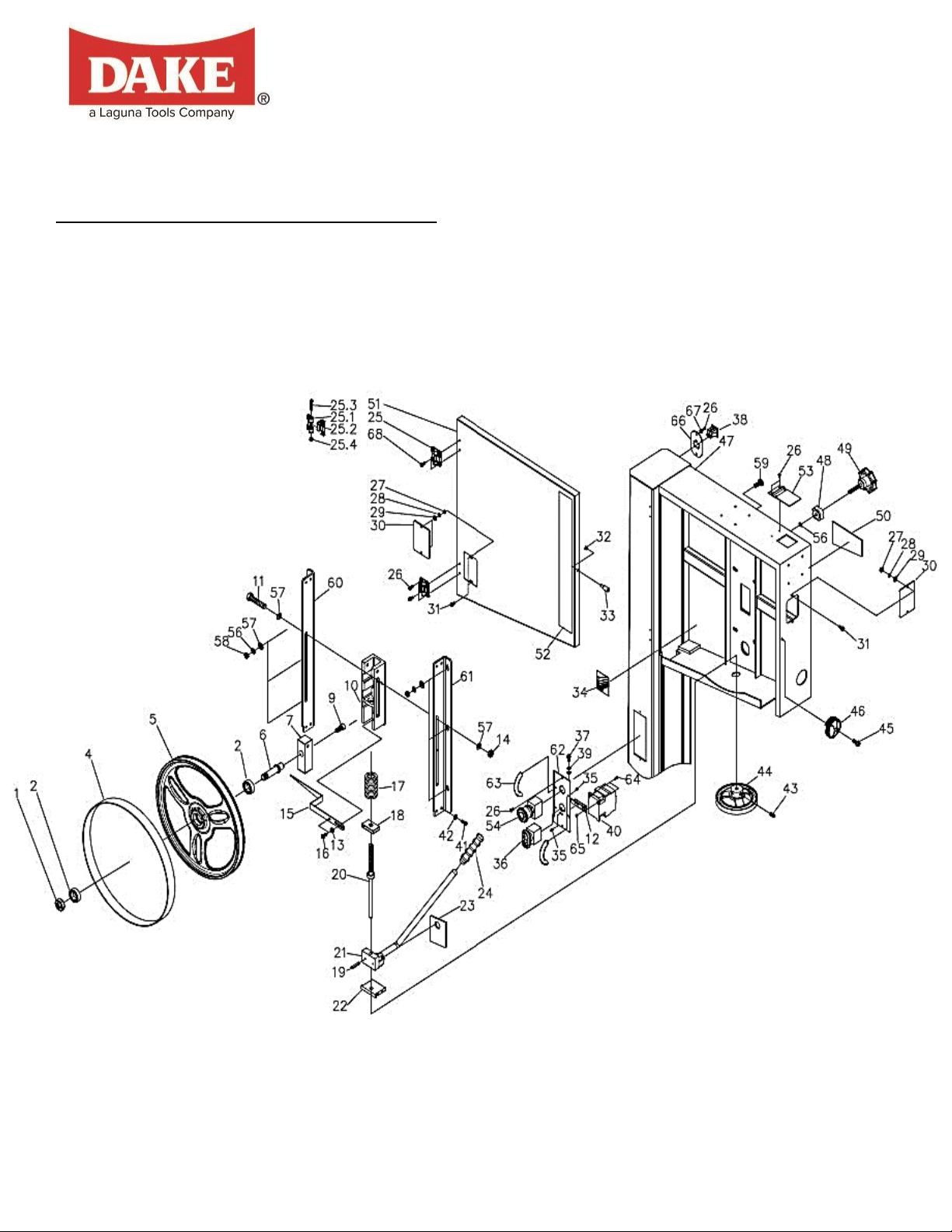
Upper Wheel Assembly: (Parts List Below)
Part# VDL-18 38 REV#082020
Page 39

Part# VDL-18 39 REV#082020
Upper Wheel Assembly
Index
Part Number
Item
Description
Specifications
Quantity
Dake Part
Number
1
PBAND18BX2203-1
Hex Nut
5/8-18UNF-LH
1
2
PBAND18BX2203-2
Ball Bearing
6204LLU
2
4
PBAND18BX2203-4
PU Tire
1
5
PBAND18BX2203-5
Upper Wheel
1
6
PBAND18BX2203-6
Upper Wheel
Shaft
1
7
PBAND18BX2203-7
Upper Wheel
Shaft Bracket
1
9
PBAND1412-175-9
Socket Head
Cap Screw
3/8”-16x5/8"
1
10
PBAND18BX2203-10
Sliding Bracket
1
11
PBAND18BX2203-11
Hex Cap Screw
M8x80
1
12
PBAND1412-175-170
Switch Plate
1
13
PBAND18BX2203-13
Bushing
1
14
PBAND18BX2203-14
Nylon Inserted
Lock Nut
M8
1
15
PBAND18BX2203-15
Pointer
1
16
PBAND18BX2203-16
Special Bolt
2
17
PBAND18BX2203-17
Spring
1
18
PBAND18BX2203-18
Bracket
1
19
PBAND1412-175-19
Pin
Ø4x20
1
20
PBAND18BX2203-20
Adjusting Screw
1
21
PBAND18BX2203-21
Blade Tension
Arm Assembly
1
22
PBAND18BX2203-22
Support Block
1
23
PBAND1412-175-23
Plate
1
24
PBAND1412-175-24
Handle
1
25
PBAND1412-175-25
Door Hinge Set
2
25.1
PBAND1412-175-25-
1
Door Hinge,
Left
2
25.2
PBAND1412-175-25-
2
Door Hinge,
Right
2
Page 40

25.3
PBAND1412-175-25-
3
Socket Head
Cap Screw
M5x0.8x35
2
25.4
PBAND1412-175-25-
4
Nylon Inserted
Lock Nut
M5x0.8
2
26
PBAND1412-175-26
Screw
M3.5x10mm
10
27
PBAND1412-175-27
Hex Nut
#10-24
4
28
PBAND1412-175-28
Lock Washer
#10
4
29
PBAND1412-175-29
Flat Washer
#10
4
30
PBAND1412-175-30
Tracking
Window
2
31
PBAND1412-175-31
Screw
#10-24×1/2"
4
32
PBAND1412-175-32
Hex Nut
1/4”-20
1
33
PBAND1412-175-33
Door Stud
1
34
PBAND18BX2203-34
Tension Gauge
1
35
MBAND14BX110-
175-35
Phillips Flat
Head Screw
M3x6
6
36
MBAND14BX110-
175-36
ON/ OFF
Switch
1
37
PBAND1412-175-37
Screw
M5x0.8x16
2
38
PBAND1412-175-38
Outlet
1
39
PBAND1412-175-39
Washer, Lock-
Int. Tooth
M5
3
40
MBAND14BX110-
175-40
Contactor
1
41
PBAND1412-175-41
Hex Cap Screw
1/4"-20x5/8"
4
42
PBAND1412-175-42
Lock Washer
1/4"
4
43
PBAND1412-175-43
Set Screw
1/4"-20x3/8"
2
44
PBAND18BX2203-44
Handwheel
1
45
PBAND1412-175-45
Screw
1/4"-20x3/4"
1
46
PBAND1412-175-46
Lock Knob
1
47
PBAND18CX110175-
47
Saw Body
1
48
PBAND1412-175-48
Lock Knob
1
49
PBAND1412-175-49
Adjusting Knob
1
50
PBAND1412-175-50
Tension Label
1
51
PBAND18BX2203-51
Upper Door
1
52
PBAND18CX110175-
52
Logo Label
1
53
PBAND1412-175-53
Hinge Cover
1
Part# VDL-18 40 REV#082020
Page 41

54
MBAND14BX110-
175-54
Emergency
Stop
1
55
PBAND1412-175-55
Warning Label
1
56
PBAND1412-175-2-
13
Lock Washer
5/16"
7
57
PBAND1412-175-2-
11
Flat Washer
5/16"
8
58
PBAND1412-175-3-
38
Hex Nut
5/16"-18
6
59
PBAND18BX2203-59
Carriage Bolt
5/16-18x1"
6
60
PBAND18BX2203-60
Upper Wheel
Bracket- Left
1
61
PBAND18BX2203-61
Upper Wheel
Bracket- Right
1
62
PBAND18CX110175-
62
Control Panel
1
63
MBAND14BX110-
175-63
Handle
2
64
MBAND14BX110-
175-64
Hex Cap Screw
M4x0.7x12
2
65
MBAND14BX110-
175-65
Hex Nut
M4x0.7
2
66
MBAND14BX110-
175-66
Plate
1
67
MBAND14BX110-
175-67
Washer, Lock-
Int. Tooth
M4
2
68
MBAND14BX110-
175-68
Screw
M4x0.7x8
4
Part# VDL-18 41 REV#082020
Page 42

Table and Fence Assembly: (Parts List Below)
Part# VDL-18 42 REV#082020
Page 43

Table & Fence Assembly Parts List
Index
Part Number
Dake Part
Number
Item
Description
Specifications
Quantity
1
PBAND18BX2203-
3-1
Aluminum
Fence
1
2
PBAND1412-175-3-
2
Plastic
Adjusting
Screw
1
3
PBAND1412-175-3-
3
Fence Body
1
4
PBAND1412-175-3-
4
Lock Knob
2
5
PBAND1412-175-3-
5
Socket Head
Cap Screw
5/16"-18x3/4"
3
6
PBAND1412-175-2-
13
Lock Washer
5/16"
10
7
PBAND1412-175-3-
7
Fence Head
1
8
PBAND18BX2203-
3-8
Lock Knob
1
9
PBAND1412-175-3-
9
Lock Bar
1
10
PBAND1412-175-3-
10
Set Screw
M4x0.7x4
4
11
PBAND1412-175-3-
11
Table Insert
1
12
PBAND18BX2203-
3-12
Table
1
13
PBAND18BX2203-
3-13
Scale
1
14
PBAND18BX2203-
3-14
Scale Plate
1
15
PBAND1412-175-3-
15
Hex Cap
Screw
M5x0.8x10
2
16
PBAND1412-175-29
Flat Washer
M5
2
17
PBAND1412-175-3-
17
Bushing
2
18
PBAND1412-175-3-
18
Socket Head
Cap Screw
5/16"-18x2-
1/2"
2
Part# VDL-18 43 REV#082020
Page 44

19
PBAND18BX2203-
3-19
Steel Tube
1
20
PBAND1412-175-3-
20
Scale
1
21
PBAND1412-175-3-
21
Trunnion
2
22
PBAND1412-175-3-
22
Hex Cap
Screw
M10x1.5x50
2
23
PBAND1412-175-3-
23
Slide Block
2
24
PBAND1412-175-3-
24
Flat Washer
1/4"
6
25
PBAND1412-175-2-
42
Lock Washer
1/4"
6
26
PBAND1412-175-3-
26
Socket Head
Cap Screw
M6x1x16
6
27
PBAND1412-175-3-
27
Pointer
1
28
PBAND1412-175-3-
28
Screw
M5x0.8x8
1
29
PBAND1412-175-3-
29
Bracket
1
30
PBAND1412-175-2-
42
Flat Washer
3/8"
2
31
PBAND1412-175-3-
31
Lock Handle
2
32
PBAND1412-175-3-
32
Hex Cap
Screw
5/16"-18x1-
1/4"
3
33
PBAND1412-175-3-
33
Set Screw
5/16"-18x5/8"
2
34
PBAND1412-175-3-
34
Hex Cap
Screw
5/16"-18x1-
3/4"
3
35
PBAND1412-175-3-
35
Hex Cap
Screw
3/8"-16×2"
1
36
PBAND1412-175-3-
36
Hex Nut
3/8"-16
1
37
PBAND1412-175-3-
37
Phillips Flat
Head Screw
M4x0.7x8
1
38
PBAND1412-175-3-
38
Hex Nut
5/16"-18
1
Part# VDL-18 44 REV#082020
Page 45

Part# VDL-18 45 REV#082020
39
PBAND1412-175-2-
11
Flat Washer
5/16"
1
40
PBAND1412-175-3-
40
Lock Handle
1
41
PBAND18BX2203-
3-41
Nylon Inserted
Lock Nut
5/16-18UNC
1
42
PBAND1412-175-3-
42
Set Screw
1/4"-20x1/4"
2
43
PBAND18BX2203-
3-43
Fence Stop
Hinge
1
44
PBAND18BX2203-
3-44
Lock Handle
1
45
PBAND18BX2203-
3-45
Fence Stop-A
1
46
PBAND18BX2203-
3-46
Fence Stop-B
1
47
PBAND1412-175-6-
26
Bushing
2
48
PBAND18BX2203-
3-48
Socket Head
Cap Screw
5/16-
18UNCx2"
1
49
PBAND18BX2203-
3-49
Square Nut
1/4-20UNC
1
50
PBAND18BX2203-
3-50
Screw
M3x0.5x4
2
51
PBAND18BX2203-
3-51
Scale
1
Page 46

Upper & Lower Blade Guides Assembly: (Parts List Below)
Part# VDL-18 46 REV#082020
Page 47

Part# VDL-18 47 REV#082020
Upper & Lower Blade Guides Assembly Parts List
Index
Part Number
Dake Part
Number
Item
Description
Specifications
Quantity
1
PBAND1412-175-
4-1
Lock Knob
1
2
PBAND1412-175-
2-8
Set Screw
5/16"-18x3/8"
2
3
PBAND1412-175-
43
Set Screw
1/4"-20x3/8"
1
4
PBAND1412-175-
4-4
Hand wheel
1
5
PBAND1412-175-
4-5
Handle
1
6
PBAND18BX2203-
4-6
Pointer
1
7
PBAND1412-175-
4-7
Screw
1/4"-20x3/8"
1
8
PBAND18BX2203-
4-8
Upper Blade
Guard
1
9
PBAND18BX2203-
4-9
Height Scale
1
10
PBAND18BX2203-
4-10
Magnet
1
11
PBAND1412-175-
4-11
Guide Bar
Bracket
1
12
PBAND1412-175-
4-12
Socket Head
Cap Screw
5/16"-18x1-
1/4"
2
13
PBAND1412-175-
4-13
C-Ring
S12
2
14
PBAND1412-175-
4-14
Worm
1
Page 48

Part# VDL-18 48 REV#082020
15
PBAND1412-175-
4-15
E-Ring
E8
2
16
PBAND1412-175-
4-16
Gear Base
1
17
PBAND1412-175-
4-17
Bushing
1
18
PBAND1412-175-
4-18
Shaft
1
19
PBAND1412-175-
4-19
Gear
1
20
PBAND1412-175-
4-20
Plate
1
21
PBAND1412-175-
4-21
Socket Head
Button Screw
5/16"-18x1/2"
4
22
PBAND18BX2203-
4-22
Guide Bar
1
23
PBAND1412-175-
4-23
Socket Head
Cap Screw
1/4"-20x5/8"
4
24
PBAND1412-175-
42
Lock Washer
1/4"
2
25
PBAND1412-175-
4-25
Lock Knob
4
26
PBAND1412-175-
4-26
Ceramic
Guide
8
27
PBAND1412-175-
4-27
Adjusting
Block
4
28
PBAND1412-175-
4-28
Fixed Block
2
29
PBAND1412-175-
4-29
Lock Knob
1
30
PBAND1412-175-
4-30
Ceramic
Guide
2
31
PBAND1412-175-
4-31
Support Shaft
1
32
PBAND1412-175-
4-32
Guide Bracket
1
33
PBAND1412-175-
4-33
Lock Handle
1
34
PBAND1412-175-
4-34
Support Shaft
1
Page 49

35
PBAND1412-175-
4-35
Lock Knob
1
36
PBAND1412-175-
4-36
Socket Head
Button Screw
1/4"-20x1/2"
2
37
PBAND18BX2203-
4-37
Base
1
38
PBAND1412-175-
4-38
Special Bolt
2
39
PBAND1412-175-
2-11
Flat Washer
5/16"
4
40
PBAND1412-175-
4-40
Hex Cap
Screw
5/16"-18x1"
4
41
PBAND1412-175-
2-13
Lock Washer
5/16"
4
Part# VDL-18 49 REV#082020
Page 50

Lower Wheel & Motor Assembly: (Parts List Below)
Lower Wheel & Motor Assembly Parts List
Part# VDL-18 50 REV#082020
Page 51

Part# VDL-18 51 REV#082020
Index
Part Number
Dake Part
Number
Item
Description
Specifications
Quantity
1
PBAND18BX2203-1
Hex Nut
5/8-18UNF-LH
1
2
PBAND18BX2203-2
Ball Bearing
6204LLU
2
3
PBAND18BX2203-2-3
Plate
1
4
PBAND18BX2203-4
PU Tire
1
5
PBAND18BX2203-2-5
Lower Wheel
1
6
PBAND18CX110175-
2-6
V-Belt
1
7
PBAND18CX110175-
2-7
Motor
Pulley,Variable
Speed
1
7A
PBAND18CX110175-
2-7A
Motor
Pulley,Cover
1
7B
PBAND18CX110175-
2-7B
Motor
Pulley,Holder
1
7C
PBAND18CX110175-
2-7C
Motor
Pulley,Slide
1
7D
PBAND18CX110175-
2-7D
Motor
Pulley,Spring
1
7E
PBAND18CX110175-
2-7E
Motor
Pulley,Bushing
1
7F
PBAND18CX110175-
2-7F
Motor
Pulley,Coupling
1
7G
PBAND18CX110175-
2-7G
Motor
Pulley,Plastic
Support Post
3
7H
PBAND1412-175-2-8
Motor
Pulley,Set
Screw
5/16"-18x3/8"
4
7I
PBAND18CX110175-
2-7I
Motor
Pulley,Pin
6x16
2
7J
PBAND18CX110175-
2-7J
Motor
Pulley,Pin
5x10
1
7K
PBAND18CX110175-
2-7k
Motor
Pulley,Pin
6x12
2
8
PBAND18CX110175-
2-8
Hex Cap Screw
3/8-16UNCx1-
3/4"
1
9
PBAND18CX110175-
2-9
Key
7x7x100
1
Page 52

10
MBAND14BX110-
175-2-10
Flat Washer
1/4"
2
76
PBAND1412-175-2-
11
Flat Washer
5/16"
2
12
PBAND18CX110175-
2-12
Spindle Pulley
1
13
MBAND14BX110-
175-2-13
Plate
1
14
MBAND14BX110-
175-2-14
Phillips Flat
Head Screw
5/16"-18x1-
1/2"
3
15
PBAND18BX2203-2-
15
Lower Spindle
1
16
PBAND1412-175-2-
16
Hex Cap Screw
M5x0.8x30
2
17
PBAND1412-175-29
Flat Washer
M5
6
18
PBAND1412-175-2-
18
Brush
1
19
PBAND1412-175-2-
19
Hex Nut
M5x0.8
4
20
PBAND1412-175-2-
20
Insert Block
1
21
PBAND1412-175-2-
21
Shelf
1
22
PBAND1412-175-2-
22
Hex Cap Screw
M5x0.8x12
2
23
PBAND1412-175-26
Screw
M3.5x10mm
6
24
PBAND18BX2203-2-
24
Lower Door
1
25
PBAND1412-175-25
Door Hinge Set
2
25.1
PBAND1412-175-25-
1
Door Hinge,
Left
2
25.2
PBAND1412-175-25-
2
Door Hinge,
Right
2
25.3
PBAND1412-175-25-
3
Socket Head
Cap Screw
M5x0.8x35
2
25.4
PBAND1412-175-25-
4
Nylon Inserted
Lock Nut
M5x0.8
2
26
PBAND1412-175-2-
26
Lock Knob
2
Part# VDL-18 52 REV#082020
Page 53

Part# VDL-18 53 REV#082020
27
PBAND18BX2203-2-
27
Lower Blade
Guard
1
28
PBAND1412-175-2-
28
Screw
1/4"-20x3/4"
1
29
PBAND1412-175-2-
29
Plate
1
30
PBAND1412-175-32
Hex Nut
1/4”-20
1
31
PBAND1412-175-33
Door Stud
1
32
PBAND1412-175-2-
32
Flat Washer
1/4”
1
33
PBAND1412-175-2-
33
Nylon Inserted
Lock Nut
1/4”-20
1
34
PBAND1412-175-46
Lock Knob
1
35
PBAND1412-175-45
Screw
1/4"-20x3/4"
1
36
PBAND1412-175-2-
36
Plate
1
37
PBAND1412-175-2-
37
Screw
#10-24×3/8"
2
38
PBAND1412-175-2-
38
Strain Relief
6N-4
4
39
MBAND14BX110-
175-2-39
Motor Cord
1
40
MBAND14BX110-
175-2-40
Power Cord
1
41
MBAND14BX110-
175-2-76
Bushing
2
42
PBAND1412-175-2-
42
Flat Washer
3/8"
7
43
PBAND1412-175-8
Lock Washer
3/8"
5
44
PBAND18BX2203-2-
44
Hex Nut
3/4"-16UNF
1
45
PBAND18CX110175-
2-45
Motor
1
MBAND14BX110-
175-2-45MF
Motor Fan (not
shown)
1
MBAND14BX110-
175-2-45MFC
Motor Fan
Cover (not
shown)
1
MBAND14BX110-
175-2-45JB
Junction Box
(not shown)
1
Page 54

Part# VDL-18 54 REV#082020
MBAND14BX110-
175-2-45JBC
Junction Box
Cover (not
shown)
1
46
PBAND1412-175-2-
46
Spindle Holder
1
47
PBAND1412-175-2-
47
Adjusting
Screw
4
48
PBAND1412-175-2-
48
Hex Cap Screw
3/8"-16×1-3/4"
5
49
PBAND18BX2203-2-
49
Flat Washer
3/4"
1
50
PBAND18BX2203-2-
50
Switch Cover
1
51
MBAND14BX110-
175-2-51
Hex Nut
M6x1.0
2
52
MBAND14BX110-
175-2-52
Limited Switch
Cord
1
53
MBAND14BX110-
175-2-53
Hex Cap Screw
3/8"-16×3/4"
3
54
MBAND14BX110-
175-2-54
Hex Cap Screw
M6x1.0x35
2
55
PBAND1412-175-3-
36
Hex Nut
3/8"-16
4
56
PBAND18CX110175-
2-56
Foot Brake
1
57
MBAND14BX110-
175-2-57
Hex Cap Screw
5/16-
18UNCx1/2
1
58
MBAND14BX110-
175-2-58
Hex Cap Screw
3/8-16UNCx1-
1/4"
1
59
MBAND14BX110-
175-2-59
Spring
1
60
MBAND14BX110-
175-2-60
Limited Switch
1
61
MBAND14BX110-
175-2-61
Screw
M3×20mm
2
62
MBAND14BX110-
175-2-62
Screw
1/4"-20x3/8"
2
63
MBAND14BX110-
175-2-63
Brake
Assembly
1
Page 55

MBAND14BX110-
175-2-63P
Brake Pad (not
shown), 2
pieces
64
MBAND14BX110-
175-2-64
Disc
1
65
MBAND14BX110-
175-2-65
Inner Cable
1
66
MBAND14BX110-
175-2-66
Housing
1
67
MBAND14BX110-
175-2-67
Plate
1
68
MBAND14BX110-
175-2-68
Socket Head
Button Screw
3/8"-16 x1"
4
69
MBAND14BX110-
175-2-69
Rubber Pad
4
70
MBAND14BX110-
175-2-70
Socket Head
Button Screw
M5x0.8x12
3
71
MBAND14BX110-
175-68
Screw
M4x0.7x8
4
72
MBAND14BX110-
175-2-72
Spacer
2
73
MBAND14BX110-
175-2-73
Plate
1
74
PBAND1412-175-4-
40
Hex Cap Screw
5/16-
18UNCx1"
4
75
PBAND1412-175-2-
13
Lock Washer
5/16"
4
76
PBAND1412-175-2-
11
Flat Washer
5/16"
4
77
PBAND18CX110175-
2-77
spacer sleeve
1
78
PBAND18CX110175-
2-78
Phillips Flat
Head Screw
3/8-16UNCx1-
1/2"
2
79
PBAND18CX110175-
2-79
Gear Plate
1
80
PBAND18CX110175-
2-80
Carriage Bolt
3/8-16UNCx1-
1/4"
1
81
PBAND18CX110175-
2-81
Flat Washer
3/8"
7
Part# VDL-18 55 REV#082020
Page 56

82
PBAND18CX110175-
2-82
Lock Handle
1
83
PBAND18CX110175-
2-83
Gear Box
Assembly
1
84
PBAND18CX110175-
2-84
Nylon Inserted
Lock Nut
3/8-16UNC
3
85
PBAND1412-175-43
Set Screw
1/4"-
20UNCx3/8"
1
86
PBAND18CX110175-
2-86
Handwheel
1
87
PBAND18CX110175-
2-87
Knob
1
88
PBAND18CX110175-
2-88
Hex Cap Screw
5/16-
18UNCx5/8"
4
89
PBAND18CX110175-
2-89
Flat Washer
5/16"
4
90
PBAND18CX110175-
2-90
Pointer
1
91
PBAND18CX110175-
2-91
Worm Gear
Assembly
1
91A
PBAND18CX110175-
2-91A
Worm
1
91B
PBAND18CX110175-
2-91B
Ball Bearing
6801ZZ
3
91C
PBAND18CX110175-
2-91C
spacer sleeve
2
91D
PBAND18CX110175-
2-91D
Gear
1
91E
PBAND18CX110175-
2-91E
spacer sleeve
1
91F
PBAND18CX110175-
2-91F
Key
4x4x8mm
1
91G
PBAND18CX110175-
2-91G
Key
4x4x18mm
1
91H
PBAND18CX110175-
2-91H
Shaft
1
91I
PBAND18CX110175-
2-91I
Ball Bearing
6802ZZ
1
91J
PBAND18CX110175-
2-91J
Gear Bracket
1
Part# VDL-18 56 REV#082020
Page 57

91K
PBAND18CX110175-
2-91K
Nylon Inserted
Lock Nut
M12x1.75
1
92
PBAND18CX110175-
2-92
Gear
1
93
PBAND18CX110175-
2-93
Plate
1
94
PBAND18CX110175-
2-94
Speed Label
1
Part# VDL-18 57 REV#082020
Page 58

VDL-18 Wiring Diagram:
Part# VDL-18 58 REV#082020
Page 59

Order Information
- Please contact factory for current prices
- Parts are available for direct purchase from Dake or through a distributor. When placing a
parts order, you will need to provide the part number, name of part, and model number. All
parts shipped F.O.B. Factory in Grand Haven, MI.
- If a customer has any questions or concerns regarding a Dake product that was purchased,
please email customer service at customerservice@dakecorp.com
Part# VDL-18 59 REV#082020
 Loading...