

Page 1

DAKE VERTICAL BAND SAW
Model V-16
INSTRUCTION MANUAL
Please record your saws information
DAKE (Division of JSJ)
724 Robbins Road
Grand Haven, Michigan 49417
616.842.7110 Phone 800-937-3253
616.842.0859 Fax 800-846-3253
Web: www.dakecorp.com
E-mail : customerservice@dakecorp.com
technicalsupport@dakecorp.com
Page 2

- 1 -
DAKE V-16 TABLE OF CONTENTS
Forward ................................................................................................ 2-3
Installation and setup............................................................................ 3-4
Specifications ....................................................................................... 4-5
Operational Controls ............................................................................. 6-7
Operation: Blade installation ... ............................................................ 7
Blade Tracking...................................................................................... 8
Guide Post Adjustment......................................................................... 8
Guide Adjustment / Holder and Guide.................................................. 9-10
Blade Selection / Type of Blades ......................................................... 10-11
Tooth Shapes ....................................................................................... 11
Set Types .............................................................................................. 11
Blade Selection Chart ........................................................................... 12
Saw Speed & Pitch Selector ................................................................. 13
Welder Operation .................................................................................. 14
Blade Cutting / Tooth Spacing............................................................... 14
Welding of the Blade ............................................................................. 15
Annealing (Carbon)................................................................................ 15
Annealing (Bi-Metal) ............................................................................. 16
Blade Dressing (Grinding) ..................................................................... 16
Weld Inspection .................................................................................... 17
Blade Weld Trouble Shooting ............................................................... 17-18
Trouble Shooting Chart / Saw /Blade / Cutting ..................................... 18-20
Maintenance.......................................................................................... 20
Exploded Diagrams and Parts Lists ...................................................... 21-25
Electrical Drawing ................................................................................. 26
Page 3

- 2 -
FOREWARD
First of all, we would like to take this opportunity to thank you for selecting our Dake V-16
model vertical Bandsaw.
As you know, the vertical bandsaw is a universal saw for contour cutting. Blade selection is
important and by choosing the right blade, you can make most any pattern cutting on most
any material with this machine. However, the most important thing is to realize how to
operate it in a safe and correct way and how to maintain it.
We have tried to supply you all the information about these. Please be sure to look through
all the contents in this manual so that you may obtain the maximum efficiency and the
longest machine life with minimum expense.
The specifications and information in this manual were current at the time this manual was
approved for printing. Dake, whose policy is one of continuous improvement, reserves the
right, however, to change specifications or design at any time without incurring obligations.
Always include the part number, model number, and parts description, for parts orders or
correspondence concerning your bandsaw, so we can supply you a rapidly after-sales
service.
1. Read the operator’s manual carefully. Learn the tools applications and limitations, as well
as the specific potential hazards peculiar to it.
2. Always wear approved safety glasses/face shields while using this machine.
3. Make certain the machine is properly grounded.
4. Before operating the machine, remove tie, rings, watches, other jewelry, and roll up
sleeves above the elbows. Remove all loose clothing and confine long hair. DO NOT
wear gloves when operating.
5. Keep the floor around the machine clean and free of scrap material, oil and grease.
6. Keep machine guards in place at all times when the machine is in use. If removed for
maintenance purposes, use extreme caution and replace the guards immediately.
7. DO NOT over reach. Maintain a balanced stance at all times so that you do not fall or
lean against blades or other moving parts.
8. Use only sharp blades. Dull blades are dangerous.
9. Make all machine adjustments or maintenance with the machine unplugged from the
power source.
10. Use the right tool. Don’t force a tool or attachment to do a job which it was not designed
for.
▲WARNING
Page 4

- 3 -
11. DO NOT make cuts requiring more power than is available on the machine.
12. Replace warning labels if they become obscured or removed.
13. Make certain the motor switch is in the OFF position before connecting the machine to
power.
14. Give your work undivided attention. Looking around, carrying on a conversation. And
“horse-play” is careless acts that can result in serious injury.
15. Make a habit of checking to see that keys and adjusting wrenches are removed before
turning on the machine.
16. Keep visitors a safe distance from the work area.
17. Use recommended accessories; improper accessories may be hazardous.
18. Never place hands directly in line with the saw blade.
19. Always use push sticks when cutting small material.
20. Raise or lower the blade guide only when the machine has been turned off and the
blade has stopped moving.
21. Read and understand warnings posted on the machine.
22. DO NOT use attachments for any other purpose than for what they were designed for.
23. Failure to comply with all of these warnings could lead to serious injury.
INSTALLATION
WARNING!!!
The machine table must NOT be used as a lifting point. Damage to the saw could
occur.
UNLOADING: Remove the shrink-wrap covering the machine, careful not to damage
painted surfaces. Carefully inspect the machine for physical damage. If damage is
noted, notify the truck line at once. They may require inspection, and that a claim be
filed. Check that all standard accessories are with the machine. Some accessories may be
boxed or placed behind the rear access door. The band saw is provided with a lifting eye
that is screwed into the top of the machine. This lifting eye may be located in the rear
compartment.
Particular care should be taken in selecting areas of the machine for handling, as electrical
components and adjustment knobs can be marked up or damaged. Remove the mounting
bolts holding the machine to the skid, using the lifting eye, remove the machine from the
skid and set in designated area.
Page 5
- 4 -
CLEANING
1. Remove anti-rust oil.
2. Remove the coating with a clean brush applied with appropriate solvent.
3. When the coating has been softened, remove it with clean rag.
POWER SUPPLY
1. Shut off the main power switch
before connecting cable.
2. Check motor voltage against
supply voltage.
3. Make sure the power supply is
connected to comply with the
local safety regulations.
4. Your saw may be pre-wired with
a power cable attached. This
cable can be hard wired or the
preferred method of installing a
properly rated quick disconnect.
▲ WARNING
All electrical connections must be done by
a qualified electrician. Failure to comply
may cause serious injury!
All adjustment or repairs must be done with
the machine disconnected from the power
source. Failure to comply may result in
serious injury!
5. The leads connect to L1, L2, and L3 and ground. The bandsaw must be grounded.
6. Check that the blade is running in the correct clockwise direction. If the blade runs
backwards, disconnect the power. Then reverse any two of the three L1, L2, and L3
leads. Do not reverse the ground.
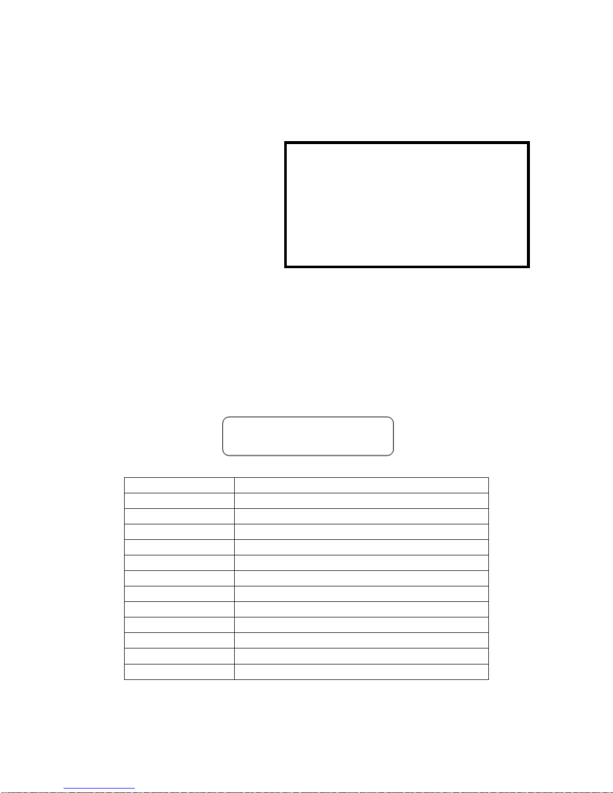
SPECIFICATIONS
Capacity
15 ½” X 10”
Blade Width Cap.
1/8” ~ 5/8”
Blade Speed
82-3,950 fpm
Table Size
21.5" x 24"
Table Tilt
R-15 ゚, L- 12゚, 8 ゚ Each F & B
Main Drive Motor
230 volt 3 Phase, 2 HP
Grinder Motor
110V, 1 Phase, 0.04 KW
Blade Length
123 ½”
Blade Welder Cap
2.4 KVA, 1/8” ~ 5/8”
Band Wheel Diameter
16”
Table Height
39”
Dimension
37” (Length) 26 ½” (Width) 72” (Height)
Mach. Weight
904 lbs.
Page 6
- 5 -
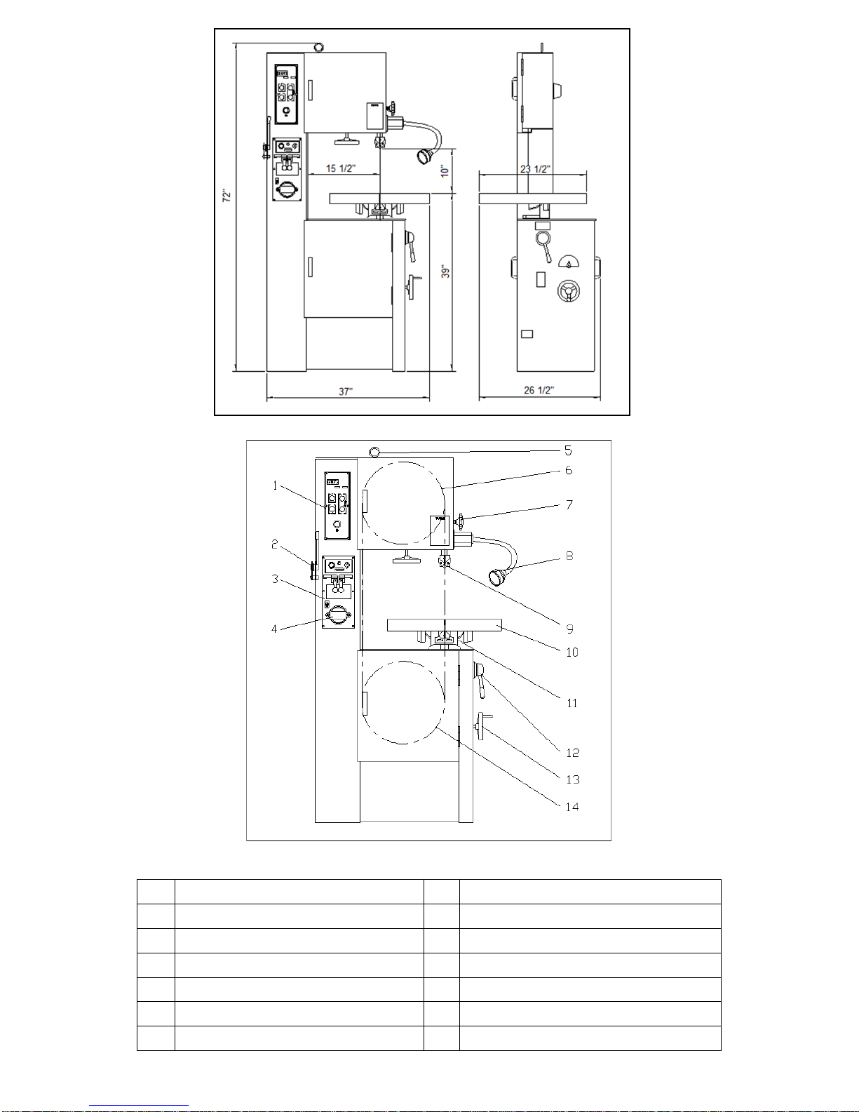
1
Control Panel
8
Work Lamp
2
Blade Shear
9
Blade Guide Supports
3
Welder Panel
10
Work Table
4
Grinding Wheel Motor
11
Table Support Housing
5
Lifting Eye
12
Low/High Range Shift Lever
6
Upper Wheel
13
Variable Speed Hand Wheel
7
Guide Post Lock Knob
14
Lower Wheel
Page 7

- 6 -
Low/High Range Shift Lever –
Located on right side of machine base. Pull toward the front of the machine to shift into the
low speed range. Push toward the rear of the machine to shift into the high-speed range.
Caution: Do not change the speed range while the machine is running. Adjust only when
the machine is stopped NOTE: If the lever will not mesh the speed range, slightly rotate the
band wheel and the lever will go into gear.
Variable Speed Hand Wheel –
Located below the worktable on right side of machine base. Turn clockwise to increase
speed and counter-clockwise to decrease speed.
Caution: Do not turn handle while machine is stopped. Adjust speed only when machine is
running. RPMs will be displayed on the control panels digital readout.
Upper Guide Post Lock Knob –
Located on right side of upper frame. Turn counter-clockwise to loosen and clockwise to
tighten. Always support the guide post when adjusting this knob to prevent unexpected
dropping of the guide post.
Work Lamp Switch – Turn lamp on and off. Caution must be used as light will be hot.
Blade Shear Lever –
Located on upper left hand side of the column. Lever up position allows insertion of the
blade into the shear. Pull lever downward to cut the blade. (This shear unit must be
mounted during set up)
Grinder Toggle Switch –
Located on the blade welder panel found on columns front. Flip switch up to start grinder;
flip down to stop grinder. This motor has temperature protection which will turn off the
power automatically when the motor is over-hearting. Motor will reset once it cools down.
Weld Button –
Located on the blade welders panel found on the front of the column. Depress and hold to
start welding. Shuts off automatically when weld is done. Release when weld is completed
Anneal Button –
Located on the blade welders panel found on the front of the column. Depress and hold to
anneal blade, release to stop.
Blade Clamp Pressure Knob –
Located on the blade welders panel found on front of the column. Sets pressure for different
width blades.
Blade Clamps –
Located on the blade welder panel found on the front of the column. Down position allows
insertion of the blade into the clamp. Up position locks blade
Blade Tension Hand Wheel –
Located on underside of the upper frame. Turn clockwise to tension the blade;
counter-clockwise to release tension on the blade.
Blade Tracking Hand Wheel –
Located at the upper rear of the saw. Turn clockwise to track the blade toward front of the
blade wheel Turn counter-clockwise to track blade toward rear of the blade wheel. (Do not
let the blade ride up onto the wheel lip)
▲CONTROLS
Page 8
- 7 -
.
Table Tilt Mechanism –
Located under worktable. To tilt table left or right, loosen hex cap screws at the rear of the
mechanism. Always tighten table bolts before operating the saw.
Power indicator Light –
Indicates that power to the control panel is on.
Key Lock Switch–
Turn the key to the 12 o’clock position and remove key to lock out power from the control
panel.
System Fuse Holder –
Holds the fuse that renders the saw inoperable when blown.
Main Motor Start Switch –
Depress to start bandsaw.
Main Motor Stop Switch –
Depress to stop bandsaw.
Emergency Stop Switch –
Press to stop the machine. Turn knob 90° to reset.
OPERATIONS
BLADE INSTALLATION
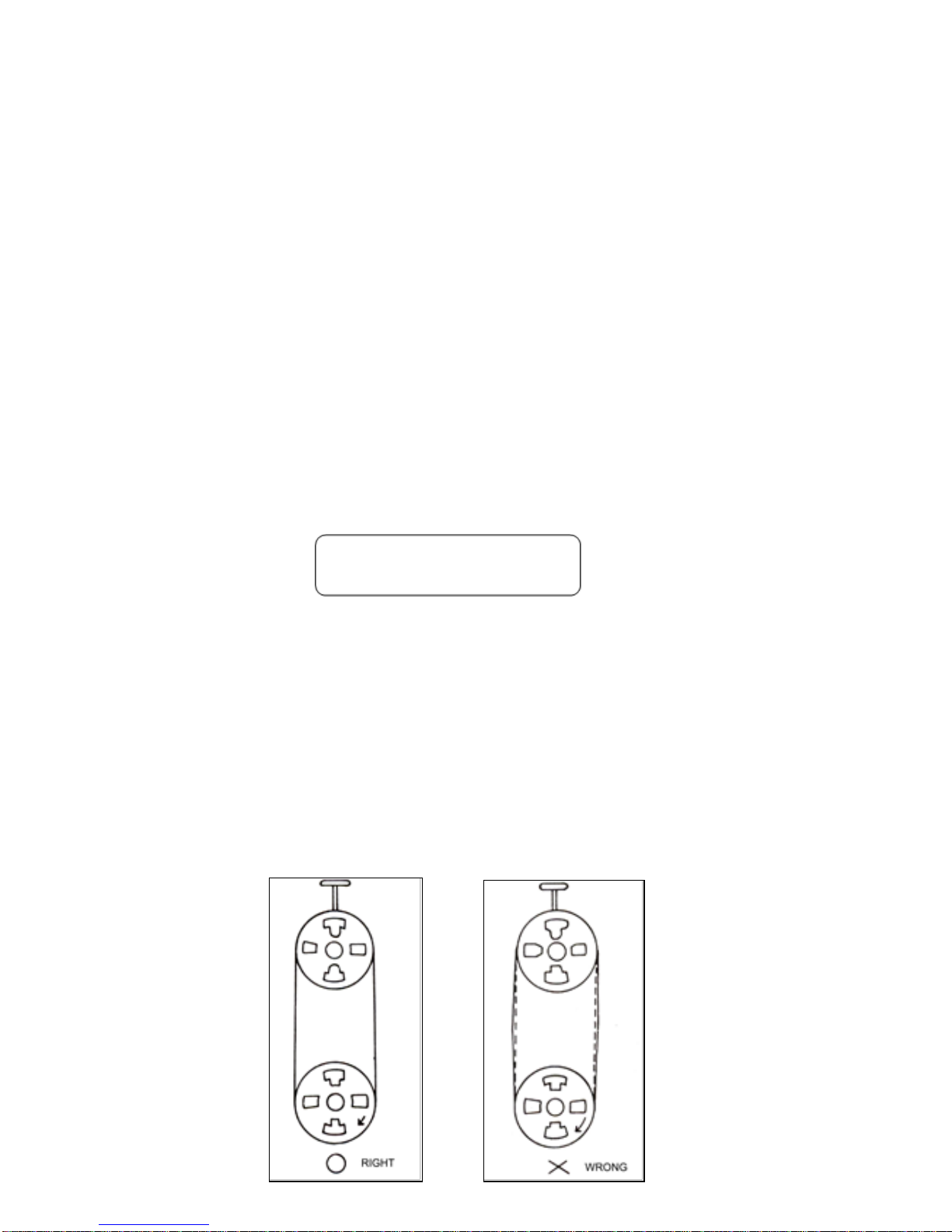
1. Install the blade as illustrated through the guides and onto the upper and lower wheels.
Replace any guarding that was removed after blade is installed.
2. Adjust blade tension per the tension scale by turning the blade tension adjustment hand
wheel. The scale is visible from the rear side.
3. Jog the machine to see if the blade tracks properly, adjust blade tracking by turning the
tracking adjuster when it is necessary. (See blade tracking section on next page for
further details)
Proper tensioning Improper tensioning
Page 9

- 8 -
BLADE TRACKING
Blade tracking may be required from time to time depending on the blade size and tension.
Disconnect the machine from the power source and open both blade wheel doors. Shift the
high-low gearbox lever into the neutral position. Turn the upper blade wheel by hand while
observing blade position on the upper blade wheel to determine if adjustment is necessary:
a. Turn blade tracking knob clockwise to track
blade toward front of blade wheel.
b. Turn counter-clockwise to track blade toward
rear of blade wheel. Blade should be tracked
as close of the center of the top blade wheel
as possible. Do not allow blade to run on the
wheel lip.
▲Note: Upper and lower blade guides should be
moved away and left loose from the blade while
tracking adjustments are being made.
GUIDE POST ADJUSTING
1. Loosen the guide post locking knob. Always
support the guide post when loosening the
guide post to prevent it from unexpectedly
falling. (Figure A next page)
2. The height of the upper guide post setting is in
relationship to the height of the material. The
height between the material and the blade
guide end is suggested to be about 1/4”. (See
figure B illustration on next page)
3. Lock the guide post tightly.
▲ WARNING
All adjustment or repairs to the machine must
be done with the power off and the machine
disconnected from the power source. Failure to
comply may result in serious injury!
Page 10

- 9 -
Figure A Figure B
▲ It may be necessary to open the blade guides, before you adjust the guide post to
allow free movement of the guide post.
GUIDE HOLDER ADJUSTMENT
1. Loosen the inner hex screws
located at the right lower side of
guide post with an “L” shaped allen
wrench.
2. Adjust the guide holder forward or
backward according to the blade
width. The front edge of the blade
guides must be adjusted about 1/8”
behind the blade teeth. (see figure B
next page)
3. Tighten the screws securely.
BLADE GUIDE ADJUSTING
1. Loosen the inner hex screws of the blade guide with an “L” shaped allen wrench.
2. Adjust the blade guides very close to the blade but not touching the guide faces. (approx.
thickness of a business card)
3. With blade tight allow guides to ride up to the blade not forcing them off center. Tighten
the blade guides securely. (See figure A next page)
NOTE: There are a total of four blade guides and two guide holders located above the
table and under the table, all to be adjusted to the same position.
Page 11

- 10 -
Figure A Figure B
The blade guides will wear after time at the
front faces. If the blade guides become hard
to be properly adjusted, turn the left blade
guide over to the right side, as illustrated in
the right illustration, and turn the right-side
blade guide over to the left side as well. The
blade guides can then be used on both sides
getting more mileage out of the guides.
The backup blade guide button will wear over
time as friction from the saw blade may cause
a worn line on its surface. If this is found to
happen, loosen the lower guide holder bolt
and turn it to rotate the button shaft to change
the buttons position on the saw blade.
▲ CAUTION
Blade guide must be properly adjusted
or damage may occur to the blade and/or
the guides.
BLADE SELECTION
To get the most satisfactory work from your saw, it is important to choose a blade that is
correct for the work. Blade life, cut straightness, finishing quality and sawing efficiency is all
related to the choice of blade. Blade breakage, teeth stripping, crooked cuts, and other
common complaints are, in most instances, caused by using the wrong blades. Blades are
classified by materials, tooth shapes, and types of set.
Page 12

- 11 -
TYPES OF BLADES
Bandsaw blades are available in specific sizes, or in 100 feet coils. They are made from
several different metals:
1. Carbon Steel Blade: which are widely used because of their general adaptability for all
types of work and the low cost. They are excellent for cutting nonferrous metals and
plastics.
2. High-Speed Steel Blade: which resist heat generated in cutting to far greater extent than
carbon steel blades. They are best suited for cutting ferrous metals.
3. Alloy Steel Blade: which are tougher and more wear resistant than either of the above.
They will cut faster and longer than blades of carbon or high-speed steel.
4. Carbide-Tipped Blade: which are best used for cutting unusual materials such as
uranium, titanium, and beryllium. These metals are difficult to cut with other types of
blades.
TOOTH SHAPES
The regular or standard tooth is preferred for all ferrous metals and general-purpose cutting.
The skip-tooth blade has widely spaced teeth to provide the added chip clearance needed
for cutting softer nonferrous materials. The hook, or saber tooth blades has a 10°undercut
which permits better feed and chip removal, it is best for the harder nonferrous alloys.
SET TYPES
Regular or rake set is generally furnished on saws that have 2 to 24 teeth per inch. These
blades have one tooth set to left, one to right, and one unset tooth called a rake. This set is
used when material is to be contour cut. Wavy set is furnished on saws that have 8 to 32
teeth per inch. This set has groups of teeth bent alternately to left and right, which greatly
reduce the strain on individual teeth. Saws with wavy set are used where tooth breakage is
a problem, such as in cutting thin stock or where a variety of work is cut without changing
blades.
Of the three common set patterns, only raker and wave are now used in metalworking.
Always use rake set except:
For work of varying cross
section use wave set.
When one blade must be
used for a range of material
sizes use wave set
Page 13

- 12 -
▲ PLEASE NOTE THAT CORRECT BLADE SELECTION IS VERY IMPORTANT TO
BANDSAW OPERATING AT FULL POTENTIAL. ALWAYS SELECT A BLADE
ACCORDING TO THE MATERIAL SHAPE AND THICKNESS OF THE WORK
Always break in the blade per blade manufactures recommendations.
SAW BLADE SELECTION
MATERIAL SHAPE
MATERIAL SHAPE
MATERIAL SHAPE
MATERIAL IN
INCHES
TOOTH SELECTION
TOOTH SELECTION
TOOTH SELECTION
0
14 / 18
14 / 18
14 / 18
.1
14 / 18
14 / 18
14 / 18
.2
14 / 18
14 / 18
14 / 18
.3
10 / 14
14 / 18
10 / 14
.4
8 / 12
10 / 14
8 / 12
.5
8 / 12
8 / 12
6 / 10
.6
6 / 10
8 / 12
5 / 8
.7
6 / 10
6 / 10
5 / 8
.8
5 / 8
6 / 10
5 / 8
.9
5 / 8
5 / 8
5 / 8
1
5 / 8
5 / 8
4 / 6
1 1/4
4 / 6
5 / 8
4 / 6
1 1/2
4 / 6
4 / 6
4 / 6
1 3/4
4 / 6
4 / 6
4 / 6
2
4 / 6
4 / 6
3 / 4
2 1/4
4 / 6
4 / 6
3 / 4
2 1/2
3 / 4
4 / 6
3 / 4
2 3/4
3 / 4
4 / 6
3 / 4
3
3 / 4
3 / 4
3 / 4
3 1/4
3 / 4
3 / 4
3 / 4
3 1/2
3 / 4
3 / 4
3 / 4
3 3/4
3 / 4
3 / 4
2 / 3
4
3 / 4
3 / 4
2 / 3
5
2 / 3
3 / 4
2 / 3
6
2 / 3
3 / 4
2 / 3
7
2 / 3
2 / 3
1.4 / 2.5
8
1.4 / 2.5
2 / 3
1.4 / 2.5
9
1.4 / 2.5
2 / 3
1.4 / 2.5
10
1.4 / 2.5
1.4 / 2.5
1.4 / 2.5
11
1.4 / 2.5
1.4 / 2.5
1.4 / 2.5
12
1.4 / 2.5
1.4 / 2.5
1.4 / 2.5
Page 14

- 13 -
Please refer to the “Speed & Pitch Selector wheel that is supplied on your saw for speeds
and feeds, radius cutting and blade pitch selection.
Select saw blades in relationship to the thickness of materials. The following suggestions
are a rule of thumb to consider when selecting a blade.
A. Select a larger pitch blade for a thicker material.
B. Select a smaller pitch blade for a thicker material.
C. Use a smaller pitch blade to obtain a smooth cutting surface.
D. Use a larger pitch blade to obtain a faster cutting speed.
E. It is important to have different blades for different applications
Page 15

- 14 -
WELDER OPERATION
This welder is for occasional use for blade repair and is not intended for welding blades on a regular basis
from bulk stock. This welder is best suited for carbon bands but with practice both carbon and bi-metal can
also be welded.
BLADE CUTTING
1. Cut the blade to the length of the
machine. Using the blade shear will insure
that the blade ends are cut flat, square and
smooth.
2. Place the back edge of blade against the
square cutting guide of the shear and firmly
pull the cutting lever down to shear the
blade. Both ends of the blade must be
sheared to allow for a good butt weld.
3. Keep the shear blade clean and free from
blade end pieces that can get trapped in the
shear.
Using the Blade Shear.
TOOTH SPACING
1. On fine-pitched blades, one or more teeth on each side of the cut must be removed by
grinding so that the cross section of the weld area of the blade is uniform. Following
these guidelines will help make the teeth uniformly spaced after the weld.
Page 16

- 15 -
▲CAUTION: If the saw blade is rusty, the rust must be ground off before the blade is welded.
WELDING
1. Turn pressure knob to “0” position.
2. Butt blade ends together and locate joint in the center between the two
electrodes.
3. Set pressure knob to blade width. (Due to the different materials and thickness of
blade, please pay especial attention to the pressure adjustment. Thicker the
blade higher the pressure setting.)
4. Press and hold welder button. Do not release until the blade joint is “red” hot.
The switch is automatic and will shut welder off after a preset time of 3 or 4
seconds and the blade returns to original color. Note: The weld joint may throw
sparks during welding so wear safety glasses and proper apparel.
ANNEALING (Carbon Blades)
1. Turn pressure knob to “0” position.
2. Release blade and center the weld joint at the front of the electrodes. (At the wider part)
3. Press and jog the annealing switch button until the weld is a “dull cherry” to “cherry red”
color. Allow the blades to cool slowly by decreasing the jogging frequency.
4. Perform the annealing operations 4 or 5 times, gradually reducing the heat each time.
5. Remove any welding dust or scale from the joint and anneal 2 or 3 more times,
successively at lower temperatures. (quicker series of press and release of annealing
button)
Page 17

- 16 -
ANNEALING (Bi-Metal)
Set up blade for annealing as mentioned above for carbon blades steps 1 & 2.
Heat the band slowly by jogging the
annealing switch button until the weld
just begins to emit light (this would be
the dullest red color) or minute puff of
smoke. The desired color may not be
visible in normal room light. Always
shade the weld area with your hand.
Cool the weld quickly by releasing the
annealing button. Repeat this
operation 4 or 5 times.
▲NOTE: This procedure should be followed both before and after grinding
BI-METAL Blades.
GRINDING THE WELDED BLADE
▲ WARNING
Keep hands away from rotating grinding wheel. When not in use make, sure
wheel is covered with built in cover
After welding, the blade must be dressed to remove excess metal or flash from the weld.
Grind the welded area down to the same thickness as the rest of the band. Handle the blade
carefully.
Grind Carefully: do not hit the teeth; or grind deeper than the thickness of the blade; or
overheat the weld area. Be sure to remove flash from the back edge of the blade. Any flash
or “stub” teeth that project beyond the normal set or height of the other teeth must be
ground off.
Anneal the welded area that was ground again. Anneal 2 or 3 times using a lower
temperature. (Just as area starts to emit light)
Page 18

- 17 -
INSPECION OF THE WELD
When the blade is removed from the
welder it should be inspected
carefully.
The spacing of the teeth should be
uniform and the weld should be
located in the center of the gullet.
Major jaw misalignment is easily
noted at this time from the weld
appearance. See the trouble shooting
chapter if the weld is imperfect.
▲CAUTION: This welder is designed for intermittent use. Repeated welding
within a short period of time may cause the welder to overheat.
TROUBLE SHOOTING
MISALIGNED WELD
(1) Dirt or scale on jaws or blade.
(2) Blade ends not cut off square.
(3) Blade ends not correctly aligned when clamped in jaws.
(4) Worn jaws or inserts.
(5) Jaws are not aligned correctly.
Page 19

- 18 -
MISALIGNED WELD-BLADE ENDS ARE OVERLAPPED
(1) Jaw Upset Force Control set for wider blade than used, re-adjust correctly.
(2) Blade ends or jaws not aligned correctly.
WELD BREAKS WHEN USED
(Joint is not complete, “blow holes” in joint)
(1) Weld not annealed correctly.
(2) Weld has been ground too thin.
(3) Weak “Incomplete” weld.
INCOMPLETE WELD (Items 3 – 8 requires welder removal)
(1) Incorrect Initial Set-Up:
(a) Initial jaw gap (weld lever position) not set correctly.
(b) Upset force control not set correctly.
(2) Improper clamping procedures.
(3) Defective cut-off switch may not break the circuit at end of welding operation.
(4) Cut-off Switch not adjusted correctly.
(5) Points of cut-off switch welded together.
(6) Slide Rod sticking because of rust or dirt. Clean and oil the rod.
(7) Slide Rod movement obstructed because the stop screw too tight on the Rod.
(8) Jaw movement obstructed by kinked jaw cable or tangled wires. Bend cable and
untangle wires.
BRITTLE WELDS
Weld has not been annealed correctly; see “Annealing” in operation chapter. Poor
annealing can be caused by:
1. Incorrect annealing heat. Bring weld up to correct color as described under “Annealing”
in welder operations chapter.
2. Scale or oil on weld can cause poor annealing.
TROUBLE SHOOTING
PROBLEM
CAUSE
SOLUTIONS
The Weld could not be made,
the Jaws do not move
A. The wire connection is poor, the
connecting point of welding
switch is bad
B. The transformer is burnt out
C. Some oil is on the blade
D. Some rust is on the blade
ends
E. The adjustment of the welding
pressure is incorrect
A. Change the welding switch.
B. Change the transformer.
C. Remove the oil
D. Grind off the rust
E. Loosen the adjusting screw
that is in center of it
The weld area melts the blade
not welds it when welding
switch is pushed
A. The welding switch cut off too
late
B. The Welding Pressure is too
weak
C. The jaw movement is too slow
A. Screw the welding switch
Connecting Nut tight
B. Turn the welding pressure
adjuster clockwise
C. Put some oil on the rear side
of the welding lever jaws
Page 20

- 19 -
The annealing job cannot be
made when pushing the anneal
button
A. The connection of annealing
switch is loose or broken
B. The fuse is blown
C. The connection of the
electrodes to blade is poor
A. Change an anneal switch
B. Change a fuse
C. Clean electrode surfaces
The grinder is not running when
the grinder switch on
A. The grinder motor is defective
B. The grinder switch is defective
A. Replace the grinder
B. Replace the switch
The blade can not be tightly
clamped with the jaw clamps
A. The jaw clamps are burnt or
defective
B. The lower jaw inserts defective
C. The Jaws are burnt or eroded
A. Change clampers
B. Change lower jaw Inserts
C. Change jaws
The annealing button will not
release to neutral position
Some dust or debris around the
anneal button restricting movement
Release the anneal button by
gently pulling it to the
neutral position
Clean out any dust or debris
Blade tooth broken
A. Incorrect pitch for the application
B. Brittle blade improper annealing
C. Inferior blade
A. Select a right pitch blade
B. Re-weld and anneal
C. Decrease feeding rate
D. Change to high quality blade
Blade damaged
A. Brittle blade improper annealing
B. Blade tension out of adjustment
C. Too Fast feeding
D. Blade teeth hitting guides.
E. Cannot cut radius without blade
twisting.
A. Decrease the annealing
temperature
B. Adjust blade tension
C. Decrease feed rate
D. Adjust a proper gap
between the blade and the
guide insert
E. Change to a narrower blade
PROBLEM
CAUSE
SOLUTIONS
Saw blade is twisted
A. Improper weld
B. Blade installed in improper way
C. Blade tension too loose
D. The blade is being over fed
A. Re-weld the blade again
B. Set the guide inserts closer
C. Increase blade tension
D. Decrease the feeding rate
when starting the cut
E. Use a proper width blade for
radius cutting
The sawing direction deviates
A. The blade tooth is not on even
or warn unevenly.
B. The blade tension is too loose
C. The guide post was set too high
A. Make sure a good blade is
used without damaged teeth
B. Increase blade tension
C. Set the guide post to be
within a ¼” of the work
D. Decrease feeding rate
Saw blade walks off
A. Blade tension is too loose
B. Blade is not tracked properly
A. Increase blade tension
B. Adjust the wheel alignment
Page 21

- 20 -
The blade dulling prematurely
A. The blade speed is too fast
B. The selection of blade is
improper
C. Feeding rate too fast
A. Slow down the blade speed
B. Use a proper blade for the
application
C. Decrease feeding rate
The blade is not cutting straight
vertically
A. The blade dull
B. The guide post is not properly
fixed
C. The blade tension is too loose
D. The blade is not exactly 90°to
the table
A. Change to a new blade
B. Fix the guide post properly ¼”
above material
C. Increase blade tension
D. Adjust it to be 90°
Excessive noise when machine
is running
A. The variable speed pulley is
damaged
C. The saw is not sitting flat on the
floor
A. Change a new pulley
B. Reposition the machine on a
flat even hard floor
MAINTENANCE
PART OR PLACE TO BE
OILDED OR GREASED
TYPE OF OIL
OR GREASE
LUBRICATING
PERIOD
REMARKS
Bearings
Gear oil
every 6 months
Gear Box:
Guide post sliding part
Grease
weekly
#1350 & #1360
Speed Change handle
Grease
every 6 months
#0600,# 0740, #7120 & #7290
Gear and thread
Grease
every 3 months
#7080 & 7110
Variable pulley
Grease
every 100 hours
#9995: V-16 only
Table slide shaft
Machine oil
N/A
Upper wheel slide block
Machine oil
monthly
#3100 & #3110
Blade Tension Screw
Grease
monthly
#3110 & #3120
Welder Jaw
(clean up daily)
Rubber Tire
(clean up daily)
Work Table Assembly
(clean up daily)
Page 22

- -
Page 23

GEAR BOX COMPONENT
GUIDE POST COMPONENT
0500
1
GEAR BOX
1311
1
UPPER GUIDE SUPPORT,
0510
1
GEAR BOX COVER
1312
1
LOWER GUIDE SUPPORT,
0520
1
GEAR
1320
4
BLADE GUIDE
0521
1
GAER
1330
2
BLADE STOPER
0530
1
SCREW NUT
1350
1
BLADE GUIDE POST
0531
1
SCREW NUT
1360
1
GUIDE POST HOUSING
0540
1
GEAR
1361
1
POST CLAMPING SPRING
0550
1
GEAR SHAFT
1370
1
BLADE GUARD, LEFT
0560
1
SHAFT COVER
1381
1
BLADE GUARD, RIGHT CE TYPE
0570
1
GEAR
1390
1
POST HOUSING PIN
0580
1
MAIN SHAFT
9015
1
GUIDE POST LOCKER
0591
1
MAIN SHAFT COVER
9210
1
HANDLE KNOB
0600
1
SPEED CHANGING SHAFT
0610
1
SPEED CHANGING ARM
0611
1
SHAFT STOPPER
0612
1
SPRING
0620
1
SLIDE BLOCK
MAIN DRIVE
0630
1
CRUTCH
0631
2
BRASS BRACKET
2000
1
MAIN DRIVE MOTOR
0632
1
BRASS BRACKET
2010
1
MOTOR PULLEY
0700
1
SPEED CHANGING LEVER
2020
2
MOTOR SUSPENSION ARM
0740
1
SHAFT HOUSING
B3310
1
V-BELT, 2010+VARIATOR
0790
1
SPEED LEVER RIGHT
BM22
1
V-BELT, 2010+4040
7070
1
PULLEY
9220
1
LEVER KNOB
B3520
1
V-BELT, 7070+VARIATOR
G6008
1
BALL BEARING
G6206
1
BALL BEARING
WHEEL COMPONENT
G6303
1
BALL BEARING
G6304
1
BALL BEARING
3010
1
LOWER WHEEL
L4030
1
OIL SEAL
3020
2
RUBBER TIRE
L5230
1
OIL SEAL
3030
1
TAPER SLEEVE
L5840
1
OIL SEAL
3040
1
WHEEL LOCKING NUT
3050
1
UPPER WHEEL
3060
2
UPPER WHEEL LOCKOR
WORK TABLE COMPONENT
3080
1
SLIDE BLOCK HOUSING
3090
1
SLIDE BLOCK SEAT
1010
1
WORK TABLE
3100
2
SLIDE BLOCK GUIDE
1021
1
TABLE SUPPORT FRAME
3110A
1
UPPER WHEEL SLIDER
1031
2
TABLE BRACKET
3116
1
SLIDER SCREW SHAFT
1060
2
WASHER, 1/2”
3120
1
WHEEL ELEVATE SHAFT
1071
4
TUBE SCREW
3121
1
SPRING
1080
2
BLADE GUARD
3150
1
WASHER
1090
1
TABLE SUPPORT HOUSING
3180
3
INDICATOR RING
1100
1
GUIDE SUPPORT HOUSING
3190
1
TENSION INDICATOR
1550
1
RIP FENCE + LOCKER
3200
1
WHEEL TILT ADJUSTER
3220
1
WHEEL TILT CONNECTER
3240
1
CONNECTER WASHER
3250
1
CONNECTER HOUSING
9030
1
HANDWHEEL
9060
1
TILT ADJUST HANDWHEEL
G6205
2
BALL BEARING
3100A
1
UPPER WHEEL SLIDER
3111
1
SLIDER COVER
3116
1
SLIDER SCREW SHAFT
3120
1
WHEEL ELEVATE SHAFT
3121
1
SPRING
Page 24

AIR PUMP COMPONENT
VARIATOR COMPONENT
4010
1
AIR PUMP HOUSING
7400
1
SPEED CHANGE SHAFT
4020
1
AIR PUMP COVER
7410
1
SHAFT BLOCK
4030
1
AIR PUMP SHAFT
7420
1
SPEED INDICATE SHAFT
4040
1
AIR PUMP PULLEY
7430
1
GEAR SHAFT ARM
4050
4
AIR PUMP LEAVE
7440
1
INDICATE GEAR SHAFT ARM
4060
1
AIR PUMP SEAT
7450
1
SPEED SHAFT HOUSING
4140
1
AIR OUTLET
7451
1
WASHER TUBE
4150
1
AIR INLET
7460
1
PUELLY SHAFT ARM
4170
1
AIR NOZZLE
7470
1
VARIABLE PULLEY SHAFT
4180
1
AIR NOZZLE CLIPPER
7500A
1
VARIABLE PULLEY
BM22
-
V-BELT, 2010 + 4040
9030
1
HAND WHEEL
G6201
2
BALL BEARING
9230
1
HAND WHEEL KNOB
9995
1
GEAR NOZZLE
B3310
-
V-BELT, 2010+VARIATOR
MAIN BODY & MISCELLANCEOUS
B3520
-
V-BELT, 7070+VARIATOR
5000
1
MAIN BODY
5100
1
REAR DOOR, RIGHT
5120
1
LOWER DOOR
8200
1
SPEED AND PITCH SELECTOR
5140
1
UPPER DOOR
8201
1
SPEED AND PITCH SELECTOR
8092
1
LUBRICATE INSTRUCTION
8202
1
SPEED AND PITCH SELECTOR
8111
1
CONTROL PLATE
8203
1
BRASS BOLT
8204
1
BRASS HANDLE
8422
1
GEAR BOX INSTRUCTION
8205
1
SELECTOR BUSHING
8712
1
INDICATOR PLATE
8743
1
TILT INDICATOR, L & R
8771
1
TILT INDICATOR, F & B
9300
2
UPPER DOOR HINGE
9310
4
HINGE
9500
6
SPRING PLATE
9590
3
HANDLE ARM
9600
1
CHIP STOPPER
9700
2
INDICTOR NEDDLE
9900
1
MAGNIFIYING GLASS
9780
1
BRUSHER BRACKET
9790
1
CHIP BRUSHER
9999
1
EYE BOLT
CONTROL SWITCH COMPONENT
6600
1
PUSH BUTTON, ON
6602
1
PUSH BUTTON, OFF,
6610
1
EMERGENCY SWITCH
6650
1
KEY SWITCH
6713
1
MAGNETIC SWITCH
6723
1
OVERLOAD STARTER
6741
1
PILOT LIGHT
6745
1
VOLTAGE REDUCER
6750
1
FUSE SEAT
6755
1
FUSE
6772
1
WIRE HOUSING
6773
2
WIRE HOUSING
6799
1
WIRING PLATE
6620
2
LIMIT SWITCH
7310
1
SPEED READOUT DETECTOR
7330
1
DIGITAL TACHOMETER
Page 25

-
Page 26

WELDER COMPONENT
6800 WORK LAMP COMPONENT
6010
3
LIMIT SWITCH
6802
1
WORK LAMP COMPONENT
6011
1
INSULATOR
Bulb - MR 16 12v 20w
6020
1
GUIDE BLOCK
6021
1
SPRING BRACKET
6030
1
GUIDE CASTING
6040
1
HOUSING
6050
1
STATIONARY JAW
6051
1
INSULATOR
6052
3
INSULATING TUBE
6053
3
WASHER, INSULATE
6054
3
SPACER
6060
2
ECCENTRIC SHAFT
6070
1
CLAMP LEVER, RIGHT
6071
1
CLAMP LEVER, LEFT
6100
1
CLAMP SUPPORT, RIGHT
6101
1
CLAMP SUPPORT, LEFT
6110
1
CLAMP PLATE, RIGHT
6111
1
CLAMP PLATE, LEFT
6120
2
CAM
6130
1
MOVING JAW
6150
1
WELD BUTTON
6161
1
LIMIT SWITCH BRACKET
6170
1
PRESSURE ADJUST KNOB
1900 SHEAR COMPONENT
6180
1
SHAFT
6200
1
CAM
1910
3
SPINDLE BUSHING
6210
1
WELD TENSION ARM
1920
1
SPINDLE LIFT
6211
1
BUSHING
1930
1
BLADE SHAFT
6220
1
SPRING, SHORTER
1940
2
VANED IRON PLATE
6230
1
SPRING, LONGER
1950
2
LOWER BLADE
6240
1
TRANSFORMER
1960
1
UPPER BLADE
6250
1
SWITCH
1970
1
JOINT PLATE, LEFT
6260
1
GRINDER MOTOR
1980
1
CHAIN JOINT, RIGHT
6270
1
SPACER
1990
1
HANDLE BAR
6280
1
GRINDER WHEEL
9210
1
KNOB
6281
1
1/4" WASHER, FLAT
6282
1
6 mm-1.0 HEX NUT
6290
1
GRINDER GUARD
6291
1
GRINDER COVER
6330
1
WELDER NAME PLATE
6340
1
INSTRUCTION LABLE
6350
1
GRINDER LABLE
6420
1
ANNEAL BUTTON
9290
2
KNOB
6170
1
PRESSURE ADJUST KNOB
6180
1
SHAFT
Page 27

 Loading...