

Page 1
Phone: 800.937.3253
www.dakecorp.com
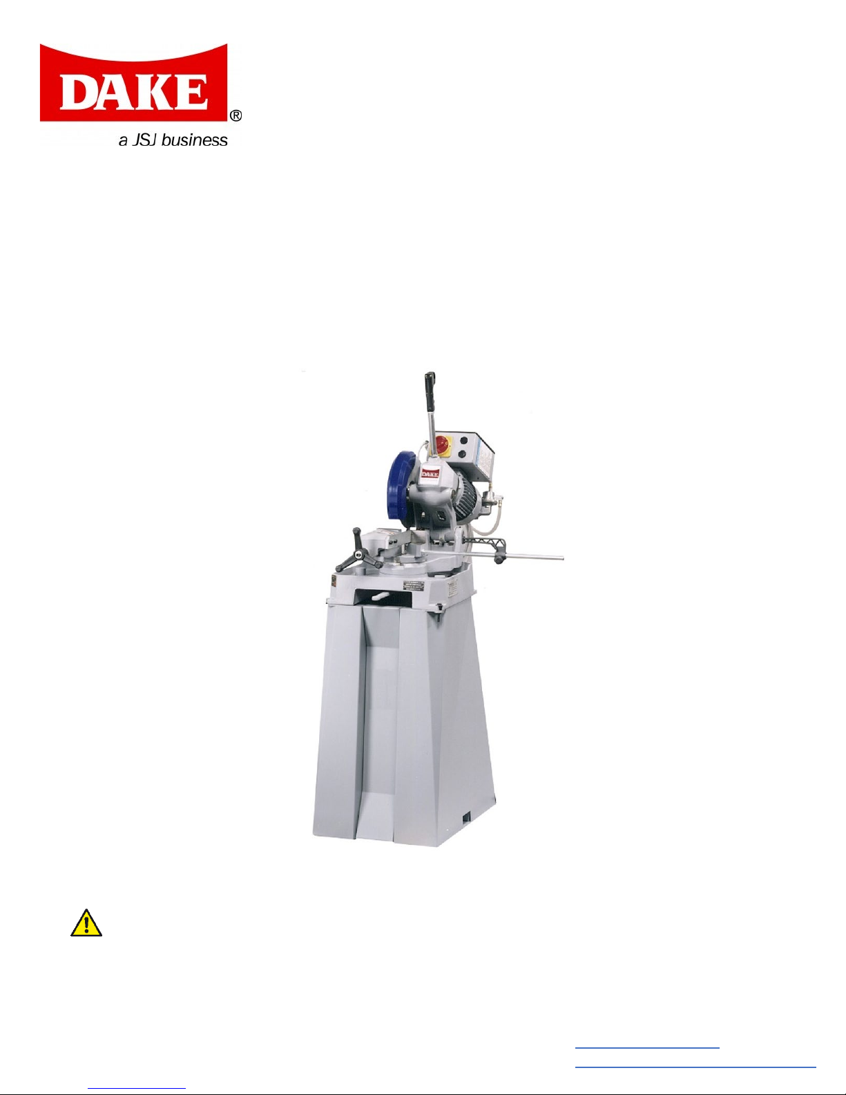
DAKE MANUAL COLD SAW
Technics 250
INSTRUCTIONAL MANUAL
WARNING!
Read and understand all instructions and responsibilities before operating. Failure to follow
safety instructions and labels could result in serious injury.
Dake Corporation
724 Robbins Road
Grand Haven, MI 49417
Fax: 800.846.3253
customerservice@dakecorp.com
Page 2

Dake Corporation
724 Robbins Road
Grand Haven, MI 49417
www.dakecorp.com
TABLE OF CONTENTS
DAKE STANDARD LIMITED WARRANTY ............................................................ 2
RETURN & REFUND POLICY .............................................................................. 3
SPECIFICATIONS ................................................................................................ 4
CUTTING CAPACITY .................................................................................. 4
SAFETY ................................................................................................................ 5
SET UP ................................................................................................................. 7
TRANSPORTING AND MOUNTING ............................................................ 7
ASSEMBLING THE MACHINE .................................................................... 7
ELECTRICAL CONNECTION ...................................................................... 8
CHOOSING A BLADE .................................................................................. 8
OPERATION ......................................................................................................... 8
STARTING THE SAW .................................................................................. 9
CHANGING THE BLADE ........................................................................... 10
MAINTENANCE .................................................................................................. 12
DAILY MAINTENANCE .............................................................................. 12
WEEKLY MAINTENANCE ......................................................................... 12
MONTHLY MAINTENANCE ....................................................................... 12
SIX MONTH MAINTENANCE .................................................................... 12
CHANGING THE GEAR BOX OIL ............................................................. 13
TROUBLESHOOTING ........................................................................................ 14
EXPLODED VIEW............................................................................................... 16
ELECTRICAL DIAGRAM .................................................................................... 17
PART LIST .......................................................................................................... 18
ORDERING INFORMATION ............................................................................... 19
1 REV012019
Page 3

Dake Corporation
724 Robbins Road
Grand Haven, MI 49417
www.dakecorp.com
DAKE STANDARD LIMITED WARRANTY
Finished Machines
Dake warrants to the original purchaser the finished machine manufactured or distributed by it to be free
from defects in material and workmanship under normal use and service within 1 year (12 months) from
the delivery date to the end user.
Parts & Couplings
Dake warrants to the original purchaser the component part or coupling manufactured or distributed by it
to be free from defects in material and workmanship under normal use and service within 30 days from
the delivery date to the end user.
The standard limited warranty includes the replacement of the defective component part or coupling, at
no cost to the end user.
Warranty Process
Subject to the conditions hereinafter set forth, the manufacturer will repair or replace any portion of the
product that proves defective in materials or workmanship. The manufacturer retains the sole right and
option, after inspection, to determine whether to repair or replace defective equipment, parts or
components. The manufacturer will assume ownership of any defective parts replaced under this
warranty.
All requested warranty claims must be communicated to the distributor or representative responsible for
the sale. Once communication has been initiated, Dake Customer Service must be contacted for
approval:
Phone: (800) 937-3253
Email: customerservice@dakecorp.com
When contacting Dake, please have the following information readily available:
- Model #
- Serial #
- Sales Order #
Purchasers who notify Dake within the warranty period will be issued a Case number and/or a Return
Material Authorization (RMA) number. If the item is to be returned per Dake’s request, the RMA number
must be clearly written on the exterior packaging. Any item shipped to Dake without an RMA will not be
processed.
Warranty Exceptions:
The following conditions are not applicable to the standard limited warranty:
(a) Part installation or machine service was not completed by a certified professional, and is not
in accordance with applicable local codes, ordinances and good trade practices.
(b) Defects or malfunctions resulting from improper installation or failure to operate or maintain
the unit in accordance with the printed instructions provided.
(c) Defects or malfunctions resulting from abuse, accident, neglect or damage outside of prepaid
freight terms.
(d) Normal maintenance service or preventative maintenance, and the parts used in connection
with such service.
(e) Units and parts which have been altered or repaired, other than by the manufacturer or as
specifically authorized by the manufacturer.
(f) Alterations made to the machine that were not previously approved by the manufacturer, or
that are used for purposes other than the original design of the machine.
2 REV012019
Page 4

Dake Corporation
724 Robbins Road
Grand Haven, MI 49417
www.dakecorp.com
RETURN & REFUND POLICY
Thank you for purchasing from Dake! If you are not entirely satisfied with your purchase, we are
here to help.
Returns
All Dake manufactured / distributed machines, parts and couplings include a 30-day return
option. These policies are valid from the date of final shipment to the end user.
To be eligible for a return, the item must be unused and in the same condition as received.
All requested warranty claims must be communicated to the distributor or representative
responsible for the sale. Once communication has been initiated, Dake Customer Service must
be contacted for approval:
Phone: (800) 937-3253
Email: customerservice@dakecorp.com
Once the return request has been approved by Customer Service, a representative will supply a
Return Material Authorization (RMA) number. The returned item must have the provided RMA
number clearly marked on the outside packaging. Any item received without an RMA number
clearly visible on the packaging will not be processed.
An RMA number can only be provided by the Dake Customer Service team and must be
obtained prior to the return shipment.
Refunds
Once the item has been received and inspected for damages, a representative will notify the
requestor referencing the provided RMA number.
If the return is approved, a refund will be issued to the original method of payment, less a 20%
restocking fee. The restocking fee may be waived if an order is placed at the time of return with
like-value merchandise.
Transportation costs are the responsibility of the end user and will not be credited upon return
approval.
Any item that is returned after the initial 30 days or has excessive/obvious use will not be
considered for a full refund.
3 REV012019
Page 5

SPECIFICATIONS
Model
Maximum feed vise opening
Number
974250E-1
Slotting
No
Voltage
110V
Maximum angle
45° right/ left
Phase
1
Weight
378 lbs
Horsepower
1.2
Work Height
37”
Speeds
44 rpm
Height
61”
Max blade diameter
10”
Base
22” x 36”
90°
1-1/8”
2-3/4”
2-1/2”
3-1/2” x 1-3/4”
45°
1”
2-3/8”
2-1/8”
2-1/2” x 2”
Serial No.
Model No.
Date Purchased:
CUTTING CAPACITY
Technics 250
Dake Corporation
724 Robbins Road
Grand Haven, MI 49417
www.dakecorp.com
4”
In the space provided record the serial number and model number of the machine. If contacting
Dake this information must be provided to assist in identifying the specific machine.
4 REV012019
Page 6

Dake Corporation
Label Part No.
84605
Label Part No.
84395
Label Part No.
76462
Label Part No.
82199
724 Robbins Road
Grand Haven, MI 49417
www.dakecorp.com
SAFETY
This is the safety alert symbol. When you see this symbol on your machine be alert to
the potential for personal injury.
Carefully read all safety messages in these instructions and on your machine safety
signs. Keep safety labels in good condition. Replace missing or damaged labels.
Employer is responsible to perform a hazard/PPE assessment before work activity.
Additional Safety Warnings:
• This machine is intended to be operated by one person. This person should be conscious
of the machine movement not only for themselves but also for persons on the immediate
area of the machine.
• This machine has been built to comply with national accident prevention regulations.
Improper use and/or tampering with the safety devices will relieve the manufacturer of all
responsibility.
• Check that the voltage indicated on the plate, normally fixed to the machine motor, is the
same as the line voltage.
• Check the efficiency of your electric supply making sure the machine has its own
grounded circuit.
5 REV012019
Page 7

Dake Corporation
724 Robbins Road
Grand Haven, MI 49417
www.dakecorp.com
• Do not operation machine without safety guards or with the electrical panel cover
removed.
• Always disconnect the machine from the power socket before changing the disk or
carrying out any maintenance job, even in the case of abnormal machine operation.
• Do not operate this machine without the handle and/or handle switch disconnected.
• Always wear OSHA approved safety glasses when operating this machine.
• Never put your hands or arms into the cutting area while the machine is operating.
• Do not shift or move machine while the machine is in operation.
• Do not wear loose clothing with sleeves that are too long, gloves, bracelets, rings,
watches, chains, or any other object that could get caught in the machine during
operation; tie back long hair.
• Keep the machine bed free from tools or any object, while the machine is in operation.
Locations of shields:
• Metal shield screwed onto the disk head. (REF. A)
• Self-regulating mobile blue plastic shield fitted coaxially with the fixed shield. (REF. B)
• Black plastic cover, covering the electrical supply box.
*picture may vary by model*
Electrical Equipment:
According to European Standard “CENELEC EN 60 204-1” which simulates modification,
publication (IED 204-1)
• The electrical equipment ensures protection against electric shock as result of direct or
indirect contact. The active parts of this equipment are housed in a box so that access is
limited. The screws can only be removed with a standard screwdriver.
• This equipment is protected against splashes of water and dust.
• This machine has been tested in conformity with EN 60204.
6 REV012019
Page 8

Dake Corporation
Shipping Bolt
Lever in closed position
724 Robbins Road
Grand Haven, MI 49417
www.dakecorp.com
SET UP
TRANSPORTING AND MOUNTING
When you receive your machine, you will need a forklift for transporting. When lifting the
machine, a sling needs to be used.
Position the machine on a firm cement floor, keeping a minimum distance from 2-1/2 feet from
any wall.
ASSEMBLING THE MACHINE
The following parts will be with your machine upon receiving: Handle and stock stop.
Removing the shipping bolt and screw the handle in the hole. There is a white plug that comes
out of the handle, plug this into its receptacle located on the side of the electrical box. There is a
lever in this attachment, move it to the closed position.
7 REV012019
Page 9

Dake Corporation
L1
L2
Ground
724 Robbins Road
Grand Haven, MI 49417
www.dakecorp.com
ELECTRICAL CONNECTION
Before connecting the machine to the main power, make sure that the installation has a
disconnected box.
The machine is not equipped with an electrical plug, the customer must provide a suitable plug
for the machine. See diagram below for wire connection. (Green/Yellow wire = Ground)
CHOOSING A BLADE
First the pitch of the teeth must be chosen, suitable for the material to be cut, according to these
criteria:
• Parts with a thing and/or variable section such as profiles, pipes, and plates, need fine
toothing, so the number of teeth used simulations cut.
• Parts with solids sections need wide spread toothing penetration.
• Material made of soft plastic, light alloys and mild bronze also require coarse toothing.
• Attached to the on/off switch on the machine you will find a blade pitch calculator (part
number 71756) with instructions on how to use.
OPERATION
Use recommendations:
• This machine has been designed to cut metal building materials with different shapes,
profiles used in workshops and mechanical structural work.
• Only one operator is needed to use the machine.
• Before starting each cutting operation, ensure that the part is firmly gripped in the vice
and that the end is suitably supported.
• Do not use cutting blades of a different size from those states in the cutting capacity
section.
• If the cutting blade gets stuck in the work piece, release the blade ON button
immediately, switch off the machine and open the vise slowly. Remove the part and make
sure that the cutting blade and/or teeth are not damaged or broken.
• Before carrying out any repairs on the machine, consult the distributor or DAKE.
8 REV012019
Page 10

STARTING THE SAW
Dake Corporation
724 Robbins Road
Grand Haven, MI 49417
www.dakecorp.com
• Mix the coolant that comes with the machine at a 10:1 ratio. Add about a half-gallon of
mixed coolant in the machine bed.
• Place material to be cut in the vice (1) and clamp the material in place by turning the
hand wheel (2) clockwise.
• Turn the power switch clockwise to the on position.
• Be sure that the blade is rotating in the correct direction indicated (the blade will rotate
clockwise, be sure the blade is on correctly, also see “changing the blade”) and check to
make sure the coolant is on.
• When the machine is now ready to cut the material. Keep in mind that the cutting speed
and the type of blade, combined with a suitable descent of the head are important for
cutting quality and machine performance.
• When starting to cut with a new blade, be sure to take out the back lash (see “changing
the blade”) on the blade in order to safeguard the blade life and efficiency. The first two or
three cuts must be made while exerting a slight pressure on the part, so that the time
taken to cut is about double the normal time.
• Grip the handle and press the button, slowly move the head in the down position and
begin to cut the material. When you are done cutting the material, release the blade and
move the head in the up position.
9 REV012019
Page 11

Grand Haven, MI 49417
www.dakecorp.com
CHANGING THE BLADE
Refer to the pictures below for part identifications.
WARNING! Before changing the blade, electrical supply must be LOCKED OUT!
Always use gloves while handling loose blades.
Dake Corporation
724 Robbins Road
1. Move the head of the saw into its upright position.
2. Using a 5mm hex wrench to remove the safety guard bolt and move the safety guard
back out of the way.
3. Using a 10mm hex wrench, turn the blade bolt clockwise to loosen. When loosened
completely remove the blade bolt and flange that holds the blade on.
a. This is a left-hand threaded bolt, to loosen clockwise turning is required.
4. Take off the old blade.
10 REV012019
Page 12

Dake Corporation
724 Robbins Road
Grand Haven, MI 49417
www.dakecorp.com
5. Clean both sides of the flange that are on either side of the blade and return the inside
flange to its place.
6. Clean all surfaces of the new blade before putting the new blade on.
a. Make sure the teeth are in the downward position, and blade turns clockwise.
b. Line up the holes of the blade with the flange pinholes of the first flange half.
7. Making sure the flange pins are lined up with the pinholes through the blade put the
second half of the flange back on to hold the blade in place.
8. Start to thread the blade bolt back on.
9. While tightening the blade bolt (counter-clockwise to tighten), pull the blade up in reverse
direction and hold it in place as tightening the bolt until it is secure.
a. This is important to remove the back lash.
10. Return safety guard back in position and secure it by screwing the safety guard bolt back
in to place.
11 REV012019
Page 13

Dake Corporation
724 Robbins Road
Grand Haven, MI 49417
www.dakecorp.com
MAINTENANCE
DAILY MAINTENANCE
• Check/fill coolant.
• Check blade wear.
• Check functionality of safety shields.
• Make sure emergency stops are working properly.
• General cleaning and removal of accumulated material.
• Move head to the full upright position when not in use, helps avoid stress on the return
spring.
WEEKLY MAINTENANCE
• Sharpen blade.
• Clean blade housing.
• Make sure the gearbox is full of oil.
• Check power chord for any damage.
• Clean and grease the screw and sliding guide vice.
MONTHLY MAINTENANCE
• Check tightness of the screws on the motor, pump, jaws, and safety guard.
• Check safety shields are not broken.
• Grease the head hinge pin.
SIX MONTH MAINTENANCE
• Change gear box oil.
• Flush coolant tank. This can be done by removing the tank cover on the back of the tank.
And remove the filter screen on the deck of the saw.
• Check all electrical components and connections in the electrical box. Saw vibration may
have loosened items wires or connections.
• Change the gearbox fluid. Drain all oil out and wipe down box and all gears before
refilling. Use 90 weight synthetic gear oil.
12 REV012019
Page 14

Dake Corporation
724 Robbins Road
Grand Haven, MI 49417
www.dakecorp.com
CHANGING THE GEAR BOX OIL
80/90 Synthetic Gear Oil, we recommend MOBIL SHC635.
Refer to pictures below for further help.
1. Disconnect machine from its power supply.
2. Remove the handle and the plug coming out of the handle that goes to the electrical
box.
3. Use a bucket to collect the old oil; unscrew sight level gauge drain the oil into the
bucket.
4. Once all oil is drained screw the bolt back in.
5. Using the hole where the handle was connected pour in oil until it is visible half way up
the sight level gauge.
6. Screw the handle back on and reconnect the plug.
7. Follow local rules and regulations to dispose of oil properly.
13 REV012019
Page 15

TROUBLESHOOTING
SYMPTOM
CAUSE
SOLUTION
Too fast of an advance on the
material
Decrease the level of
downward feed
Change the blade speed or
the diameter of the blade
Use the blade calculator to
consult your blade provider
Speak with blade provider
and sharpener
Check the material for
Check the condition of the
Check the level of coolant in
coolant.
Use the blade calculator to
consult your blade provider
Wrong cutting speed or feed
Check the level of coolant in
coolant
Too fast of an advance on the
material
Decrease the level of
downward feed
Cutting speed too slow
Increase blade speed
Use the blade calculator to
consult your blade provider
Check the level of coolant in
coolant
Dake Corporation
724 Robbins Road
Grand Haven, MI 49417
www.dakecorp.com
Wrong cutting speed
Tooth Breakage
Premature Blade Wear
Wrong tooth pitch
Low quality and/or dull blade
Poor clamping pressure
causing the part to move
Insufficient coolant or
incorrect type of coolant
Wrong blade being used
Insufficient coolant or
incorrect type of coolant
determine the correct pitch or
tightness before cutting
jaw faces
tank and increase the flow of
Talk to your coolant provider
determine the correct pitch or
tank and increase the flow of
Talk to your coolant provider
Blade sticks in the cut
14 REV012019
Wrong blade
Stick accumulation of material
on blade
Insufficient coolant
determine the correct pitch or
Use a higher quality of blade
Check the blend of coolant
tank and increase the flow of
Talk to your coolant provider
Page 16

SYMPTOM
CAUSE
SOLUTION
Control power indicator light
Emergency switch is
depressed
Pull switch out and make sure
contacts are operating
Wait 10-15 for motor to cool,
rewound
Check the incoming and the
should be 24 volts
Check voltages to relay
replaced
Socket and/or plug
Check the plug connections
Make sure there is incoming
Check to see if it spins freely
voltage from the connector.
does not work
Dake Corporation
724 Robbins Road
Grand Haven, MI 49417
www.dakecorp.com
Bad fuses Check and/or change fuses
Faulty power supply Check incoming power
Short circuit Test for short and repair
Bad light bulb Replace light bulb
Speed switch is off Turn switch to desired speed
check for continuity on the
Thermal overload tripped
two thermal overload wires, if
none, change motor or it have
Motor will not work bit the
indicator light is on
Transformer
Auxiliary Relay
connecting the switch handle
to the electrical box
Switch inside the handle
Main connection
outgoing voltages which
terminals, should be 24 volts.
If not check for loose wires, if
none relay should be
and the wire connections
inside the handle switch
Make sure the switch makes
the connection when pressed
power and outgoing when the
handle switch is made, no
shorts if so, change the
connector
*All electrical troubleshooting should be done by a qualified electrician or a technician with a
working knowledge for machine electrical systems.
15 REV012019
Motor
and it is not burnt, may need
to be changed or rewound.
Check to see if it is receiving
Page 17

EXPLODED VIEW
Dake Corporation
724 Robbins Road
Grand Haven, MI 49417
www.dakecorp.com
16 REV012019
Page 18

ELECTRICAL DIAGRAM
Dake Corporation
724 Robbins Road
Grand Haven, MI 49417
www.dakecorp.com
17 REV012019
Page 19

PART LIST
1
Pedestal
302983
65
Vise Jaw Washer
AFB8B037
Socket Head Bolt
(M12-1.75 x 25mm)
3
Revolving Arm Lock Pin
303041
67
Bearing (6031)
84101027
Revolving Arm Lock
Bushing
Revolving Arm Lock
Lever
Screw (M8-2.25 x
20mm)
7
Pin (Ø 6mm x 36mm)
82504217
79
Head Return Spring
AFC10021
10
Stock Stop Rod
AFC10047
82
Head
303291
11
Stock Stop
ANC10046
83
Rear Motor Flange
AHH80005
12
Quick Lock Vise
302823
84
Motor Fan
74310007
14
Screw M12
81110133
85
Eccentric Bearing (609)
84101016
15
Vise Jaw Washer
AFB8B037
86
Fan Cover
AHH8006
16
Screw M12
81110133
87
Retaining Ring (M10)
303289
Vise Adjusting
Handwheel
Socket Cap Screw
(M8-1.25 x 20mm)
Socket Head Cap
Screw (M6-1.0 x 20mm)
Filter Support Flange
Assembly
Socket Head Cap
Screw (M5 x 12mm)
Socket Head Cap
Screw (M6-1.0 x 20mm)
Washer
(8.5mm ID x 21mm OD)
Coolant Flow Control
Valve
Motor to Gear Box
Gasket
32
Screw (M6-1.0 x 60mm)
303043
96
Spring Connector
AFC10024
Hex. Cap Screw
(M10-1.5 x 30mm)
Hex Cap Bolt
(8mm x 1.25 x 55mm)
Motor Fly Wheel
Washer
Socket Head Bolt
(M12-1.75 x 25mm)
37
Spring Tie-Rod
302851
115
Vice Jaw
303040
Socket Head Bolt
(M12-1.75 x 25mm)
40
Head Pull Handle
AF190052
117
Lever Bushing
AFB80032
41
Hex. Nut (M16)
81600016
118
Quick Lock Vice Lever
AGB80031
Dake Corporation
724 Robbins Road
Grand Haven, MI 49417
www.dakecorp.com
Item Part Name Part No.
2 Revolving Arm AG190046
4
5
6
18
22
303042
AG160022
80521
47100000
80521
Item Part Name Part No.
66
68 Ring Nut (M15 x 1) 81700015
69 Bearing 302901
70 Front Motor Flange 302899
88 Coolant Pump Housing AG190044
89
303039
64179
24-27
28
29
30
31 Coolant Feed Tube 69102002
33 Coolant Reservoir AFB80044
34
35
36 Hinge Pin 303011
39 Hinge Pin Bushing 303290
ANC10071
64180
82100000
88600000
302413
D80C0083
90 Coolant Pump 8814100
91
92 Oil Plug 88302002A
93 Worm Screw AF180015
94
100
112 Quick Lock Vice 302823
113 Vice Jaw Washer AFB8B037
114
116
64179
ANC10002
81505
303039
303039
18 REV012019
Page 20

Dake Corporation
42
Handgrip
44600001
119
Bearing
84500001
O-Ring
(ID 30mm x OD 40mm)
44
Oil Plug
88302002
121
Pin (Ø6mm x 36mm)
82504217
45
Spindle
AFC10010
122
Vice Handwheel
47100000
Washer
(8.5mm ID x 21mm OD)
Vice Came Lever
Spring
Socket Cap Screw
(M12-1.75 x 35mm)
Fixed Upper Blade
Guard
51
Set Screw (M6 x 10mm)
78828
131
Remote Control Switch
302961
52
Coolant Nozzle
AFC10091
132
Fuse Holder
73142005
53
Lower Blade Guard
AHC20086
133
Transformer 30VA
73327011
54
External Snap Ring
82600000
134
Socket Connector
73600005
Blade Guard Mounting
Pin
Socket Cap Screw
(M6 x 12mm)
57-60
Blade Guard Support
AFC10088
137
Reset Button
716812
61
Elastic Pin (Ø 5mm)
82504189
138
Emergency Stop
716538
Socket Cap Screw
(M8-1.25 x 20mm)
63
Worm Gear
ABC10016
140
Electrical Box Cover
N/A
Socket Cap Screw
(M8-1.25 x 20mm)
Motor, 110V Single
Phase
-
Hex Socket Plug
302020
724 Robbins Road
Grand Haven, MI 49417
www.dakecorp.com
Item Part Name Part No.
43
47 Drive Pins AFC10013
48 Blade Flange AFC10011
49
50
55
56
86001049
S1110136
AGC20085
AF190092
80625
Item Part Name Part No.
120 Vice Jaw Washer AFB80033
124
125
126 Vice Screw 99300126
127 Anti-Burr Arm 302961
135 Plug Connector 73600052
136 Main Power Shut Off 70201011
82100000
AFB80035
62
64
80521
80521
139 Electrical Box 230E0017
-
302933
Please contact factory for current prices.
ORDERING INFORMATION
Parts are available for direct purchase from Dake or through a distributor. When placing a parts
order, you will need to provide the part number, name of part, and model number. All parts
shipped F.O.B. Factory in Grand Haven, MI
19 REV012019
 Loading...