

Page 1

Phone: 800.937.3253
www.dakecorp.com
DAKE DRILL PRESS
TB16, SB16, SB25, & SB32
INSTRUCTIONAL MANUAL
WARNING!
Read and understand all instructions and responsibilities before operating. Failure to follow
safety instructions and labels could result in serious injury.
Dake Corporation
724 Robbins Road
Grand Haven, MI 49417
Fax: 800.846.3253
customerservice@dakecorp.com
Page 2

Dake Corporation
724 Robbins Road
Grand Haven, MI 49417
www.dakecorp.com
TABLE OF CONTENTS
DAKE STANDARD LIMITED WARRANTY ............................................................ 2
RETURN & REFUND POLICY .............................................................................. 4
SPECIFICATIONS ................................................................................................ 5
SAFETY ................................................................................................................ 6
SET UP ................................................................................................................. 8
UNCRATING AND INSTALLATION ............................................................. 8
GROUNDING INSTRUCTIONS ................................................................... 9
OPERATION ......................................................................................................... 9
DRILL/CHUCK INSTALLATION ................................................................... 9
INSTALLATION OF DRILL BIT .................................................................. 10
TOOLING REMOVAL................................................................................. 10
TABLE HEIGHT ADJUSTMENT ................................................................ 10
TABLE SWING ADJUSTMENT .................................................................. 11
FEED DEPTH ADJUSTMENT .................................................................... 11
WORK HOLDING ....................................................................................... 12
SPEED ADJUSTMENT .............................................................................. 12
SAFETY FEATURES ................................................................................. 14
MAINTENANCE .................................................................................................. 15
TROUBLESHOOTING ........................................................................................ 16
ELECTRICAL DIAGRAMS .................................................................................. 17
EXPLODED VIEWS & PART LISTS .................................................................... 18
ORDERING INFORMATION ............................................................................... 23
1 REV012019
Page 3

Dake Corporation
724 Robbins Road
Grand Haven, MI 49417
www.dakecorp.com
DAKE STANDARD LIMITED WARRANTY
Finished Machines
Dake warrants to the original purchaser the finished machine manufactured or distributed by it to
be free from defects in material and workmanship under normal use and service within 1 year
(12 months) from the delivery date to the end user.
Parts & Couplings
Dake warrants to the original purchaser the component part or coupling manufactured or
distributed by it to be free from defects in material and workmanship under normal use and
service within 30 days from the delivery date to the end user.
The standard limited warranty includes the replacement of the defective component part or
coupling, at no cost to the end user.
Warranty Process
Subject to the conditions hereinafter set forth, the manufacturer will repair or replace any portion
of the product that proves defective in materials or workmanship. The manufacturer retains the
sole right and option, after inspection, to determine whether to repair or replace defective
equipment, parts or components. The manufacturer will assume ownership of any defective
parts replaced under this warranty.
All requested warranty claims must be communicated to the distributor or representative
responsible for the sale. Once communication has been initiated, Dake Customer Service must
be contacted for approval:
Phone: (800) 937-3253
Email: customerservice@dakecorp.com
When contacting Dake, please have the following information readily available:
- Model #
- Serial #
- Sales Order #
Purchasers who notify Dake within the warranty period will be issued a Case number and/or a
Return Material Authorization (RMA) number. If the item is to be returned per Dake’s request,
the RMA number must be clearly written on the exterior packaging. Any item shipped to Dake
without an RMA will not be processed.
2 REV012019
Page 4

Grand Haven, MI 49417
Warranty Exceptions:
The following conditions are not applicable to the standard limited warranty:
(a) Part installation or machine service was not completed by a certified professional, and
is not in accordance with applicable local codes, ordinances and good trade practices.
(b) Defects or malfunctions resulting from improper installation or failure to operate or
maintain the unit in accordance with the printed instructions provided.
(c) Defects or malfunctions resulting from abuse, accident, neglect or damage outside of
prepaid freight terms.
(d) Normal maintenance service or preventative maintenance, and the parts used in
connection with such service.
(e) Units and parts which have been altered or repaired, other than by the manufacturer
or as specifically authorized by the manufacturer.
Dake Corporation
724 Robbins Road
www.dakecorp.com
(f) Alterations made to the machine that were not previously approved by the
manufacturer, or that are used for purposes other than the original design of the
machine.
3 REV012019
Page 5

Dake Corporation
724 Robbins Road
Grand Haven, MI 49417
www.dakecorp.com
RETURN & REFUND POLICY
Thank you for purchasing from Dake! If you are not entirely satisfied with your purchase, we are
here to help.
Returns
All Dake manufactured / distributed machines, parts and couplings include a 30-day return
option. These policies are valid from the date of final shipment to the end user.
To be eligible for a return, the item must be unused and in the same condition as received.
All requested warranty claims must be communicated to the distributor or representative
responsible for the sale. Once communication has been initiated, Dake Customer Service must
be contacted for approval:
Phone: (800) 937-3253
Email: customerservice@dakecorp.com
Once the return request has been approved by Customer Service, a representative will supply a
Return Material Authorization (RMA) number. The returned item must have the provided RMA
number clearly marked on the outside packaging. Any item received without an RMA number
clearly visible on the packaging will not be processed.
An RMA number can only be provided by the Dake Customer Service team and must be
obtained prior to the return shipment.
Refunds
Once the item has been received and inspected for damages, a representative will notify the
requestor referencing the provided RMA number.
If the return is approved, a refund will be issued to the original method of payment, less a 20%
restocking fee. The restocking fee may be waived if an order is placed at the time of return with
like-value merchandise.
Transportation costs are the responsibility of the end user and will not be credited upon return
approval.
Any item that is returned after the initial 30 days or has excessive/obvious use will not be
considered for a full refund.
4 REV012019
Page 6
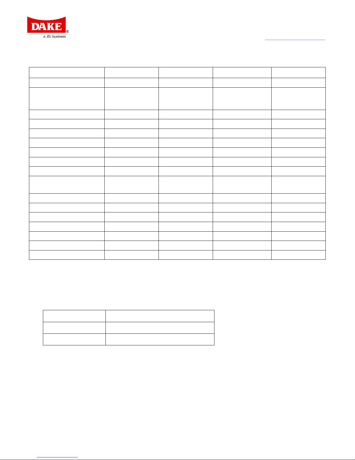
SPECIFICATIONS
Model
TB-16
SB-16
SB-25
SB-32
Number
977100-1
977200-1
977300
977400-2
110V Single
220V 3-Phase
Horsepower
1/2 HP
1/2 HP
2 HP
2 HP
Drill Type
Bench
Floor
Floor
Floor
Max. Drill Capacity
5/8”
5/8”
1”
1-1/4”
Spindle Taper
MT2
MT2
MT3
MT4
Spindle Travel
3-1/8”
3-1/8”
5”
5-1/4”
Max. Work Diameter
14-1/8”
14-1/8”
18”
18”
Speeds (Step Pulley)
9 9 9
9
Range
Column Diameter
3-1/8”
3-1/8”
3-5/8”
4”
Table
11-3/4” x 11-3/4”
11-3/4” x 11-3/4”
13-3/4” x 13-3/4”
15-3/4” x 15-3/4”
Base
17-3/4” x 12-1/4”
19-5/8” x 12-1/2”
23-5/8” x 15”
23-5/8” x 15”
Spindle to Table
16-1/2”
28-1/2”
28-3/8”
26-1/8”
Spindle to Base
26-1/2”
49-1/4”
50”
50”
Overall Height
42-1/2”
64”
71”
71”
Weight
175 lbs.
230 lbs.
397 lbs.
483 lbs.
Serial No.
Model No.
Date Purchased:
Dake Corporation
724 Robbins Road
Grand Haven, MI 49417
www.dakecorp.com
Voltage
Spindle Speed
120V 110V/220V
240-3400 RPM 240-3400 RPM 270-2000 RPM 270-2290 RPM
Phase,
220V
3-Phase
In the space provided record the serial number and model number of the machine. If contacting
Dake this information must be provided to assist in identifying the specific machine.
5 REV012019
Page 7

Dake Corporation
Label Part No.
84395
Label Part No.
76462
Label Part No.
82199
Label Part No.
300168
724 Robbins Road
Grand Haven, MI 49417
www.dakecorp.com
SAFETY
This is the safety alert symbol. When you see this symbol on your machine be alert to
the potential for personal injury.
Carefully read all safety messages in these instructions and on your machine safety
signs. Keep safety labels in good condition. Replace missing or damaged labels.
Employer is responsible to perform a hazard/PPE assessment before work activity.
Additional Safety Warnings:
• Operation of the drill press incorrectly, or on a dangerous fashion can result in serious
injury or death, damage to the machine, it’s components, or cutting tool.
• The drill press is designed for drilling and boring operations. Cautions is required when
operating the drill press because it can be dangerous due to the high spindle rotation
speed.
• Guards such as pully cover and chuck guard must be in place and in working condition to
prevent hazard.
• Switch the power off before setting, inspecting, lubricating, cleaning, or changing the drill
bit.
• Always wear eye protection.
6 REV012019
Page 8

Dake Corporation
724 Robbins Road
Grand Haven, MI 49417
www.dakecorp.com
• Do not wear gloves, neckties, necklaces, rings, or loose clothing. Non-slip footwear is
recommended. Wear protective hair covering to contain long hair.
• To clamp work piece to brace against column to prevent material rotation.
• Using recommended speed for drill bit, and work piece material.
• Remove adjusting key and wrenches. Be in the habit of checking to see that keys and
adjusting wrenches are removed from tool before turning the machine on.
• Keep work area clean. Cluttered areas and benches invite accidents.
• All visitors should be kept a safe distance from work area.
• Make workshop kid proof with padlocks, master switches, or by removing the starter key.
• Do not force tool. Machine will do a better and safer job at the rate for which it was
designed.
• Use the right tool. Do not force the tool or use the machine to do a job for which it was
not designed.
• Use recommended speed for drill accessories and workpiece material.
• Use a face or dust mask if cutting operation is dusty.
• Secure work. Use clamps or a vise to hold work, do not hold part with hands.
• Do not overreach. Keep proper footing and balance at all times.
• Maintain tool with care. Keep tools sharp and clean for best and safest performance.
• Disconnect drill press from power before servicing or changing accessories.
• Reduce the risk of accidental starting. Make sure switch is in off position before plugging
in.
• Use recommended accessories. The use of improper accessories may cause risk of
injury.
• Never stand on machine for risk of serious injury.
• Check for damaged parts. Before further use of machine, a guard or other part that is
damaged should be replaced or repaired. Carefully check to determine that it will operate
properly and perform its intended function. Check alignment of moving parts, binding of
moving parts, breakage of parts, mountings, and any other conditions that affect its
operation.
• Never leave tool running unattended. Turn power off. Do not leave machine until it comes
to a complete stop.
• Adjust the table or depth stop to avoiding drilling into the table, shut off the power.
Remove the drill bit or cutting tool, and clean the table before leaving the machine.
• Do not operate until completely assembled and installed according to the instructions.
• If any part of your drill press is malfunctioning, has been damaged, or broken do not
operate until the part is properly repaired or replaced.
• Never place your fingers in positions where they could contact the drill or other cutting
tool if the work piece should unexpectedly shift.
• Never perform any operation by moving the head or table with respect to one another. Do
not switch machine on or start any operation before checking that the head and table lock
7 REV012019
Page 9

Dake Corporation
724 Robbins Road
Grand Haven, MI 49417
www.dakecorp.com
handle are clamped tight to the column, and head and table support collars are correctly
positioned.
• Before switching the power on be sure the belt cover is down, and the bit is installed
properly in the chuck.
• Lockout the motor switch when leaving the drill press. Don’t perform layout, assembly, or
setup work on the table while the cutting tools rotating.
Voltage Warning:
• Before connecting the machine to a power source know your incoming voltage.
• At power source with voltage greater than that specified for the machine can result in
serious injury to the user and can damage the machine.
• Using a power source with voltage less than that of the machines rating can damage the
motor and other components.
• If you are unsure of the voltage rating do not use the machine.
SET UP
UNCRATING AND INSTALLATION
1. Location of the drill press should be in a well-lit area with correct power supply and that
will not interfere with other machines or operations.
2. Carefully uncrate machine and inspect all packing to make sure no parts are manuals
are thrown out.
3. When transporting the machine please use caution. If using a sling have someone
steady the machine while moving.
4. Install your drill press on a sturdy level floor surface, or workbench. The machine must
be anchored to the floor or workbench securely, the machine is top heavy.
5. Connect appropriate power to the machine. Make sure circuit breakers are suitable for
the machine. Consult local codes for proper installation of machine. Always route power
cables in a safe manner away from traffic areas, damp areas, heat, and moving parts.
6. After installing the drill press, use the kerosene or degreasing product to clean off the
anti-rust oil which was applied at the factory. Then wipe machined surfaces with a light
coating of lubricant oil (way oil).
7. Check for damaged parts before further use of the machine. A guard or other part that is
damaged should be replaced or repaired before use. Carefully check to determine that it
will operate properly and perform its intended function. Check for alignment of moving
parts and binding od moving parts. Breakage of parts or mountings and or any other
conditions that could be affect its operation.
8 REV012019
Page 10

Dake Corporation
724 Robbins Road
Grand Haven, MI 49417
www.dakecorp.com
GROUNDING INSTRUCTIONS
In the event of a malfunction or breakdown, grounding provides a path of least resistance for
electric current to reduce the risk or electrical shock. This machine is equipped with an electric
cord must be used with a matching outlet that is properly installed and grounded in accordance
with all local codes and ordinances.
• Do not modify the plug provided. If it will not fit the outlet have the proper outlet installed
by a qualified electrician.
• Improper connection of the equipment grounding can result in a risk of electrical shock.
The conductor with insulation having an outer surface that is green with yellow stripes is
equipment grounding conductor. If repair or replacement of the electric cord or plug is
necessary, do not connect the equipment grounding conductor to a live terminal.
• Check with a qualified electrician or serviceman if the grounding instructions are not
completely understood, or if in doubt as whether the machine is properly grounded.
• It is not recommended to use an extension cord on the machine. If one must be used,
use only a grounded cord on the machine and length of run needed.
• Repaired or replace damaged or worn cords immediately.
OPERATION
DRILL/CHUCK INSTALLATION
1. Before inserting drill bits, chucks, or arbors always clean out the spindle hole and taper
hole with a clean cloth.
2. Open chuck jaws completely by turning attached chuck key counter-clockwise until the
jaws are fully opened.
3. To install the chuck to the arbor tightly, slide the chuck into the taper forcing it into the
spindle with by handle.
4. Place a block of wood on the table then lower the spindle to contact the wood and press
the chuck tightly into the spindle taper.
5. Install a taper shaft drill into the taper the same way as you would the chuck. If an
adaptor is used it must fit the taper correctly and the bit must fit snug in the adaptor.
9 REV012019
Page 11

Dake Corporation
724 Robbins Road
Grand Haven, MI 49417
www.dakecorp.com
INSTALLATION OF DRILL BIT
A drill bit with a shaft of at least 1” long should be used to allow correct chuck jaw contact. If the
shaft is under 1” do not insert bit as far into the chuck where it allows jaw contact with the drill
flutes.
Center drill bit into the chuck and tighten the chuck securely with the chuck key.
Note: Always use sharp, straight bits. Never use bits with turned down shafts. Never exceed the
maximum shaft diameter bit size for the machine.
TOOLING REMOVAL
1. Before removing the chuck or bit form the machine be sure the spindle has come to
complete stop and power is off.
2. If needed rotate spindle by hand to align the spindle and quill openings.
3. Insert the wedge removal tool while supporting the tooling tap the wedge to remove the
tooling.
TABLE HEIGHT ADJUSTMENT
1. Loosen the clamp bolt then adjusting the table with the bracket handle to desired work
height.
2. Retighten the clamp securely when table is adjusted to desired height.
Note: Keep table adjustment rack clean from debris. Never attempt to move table with clamp
bolt tightened.
10 REV012019
Page 12

Dake Corporation
724 Robbins Road
Grand Haven, MI 49417
www.dakecorp.com
TABLE SWING ADJUSTMENT
1. To swing the table up to 360°, loosen the clamp release bolt and swing the table to the
desired position.
2. After table is in the correct position, tighten clamp release bolt securely.
Note: Never swing the table if any material or fixturing is on it. Only adjust when table is free
of loose articles.
FEED DEPTH ADJUSTMENT
1. Setting the feed depth adjustment is done by loosening the clamp bolt on the spindle
depth index sleeve.
2. Rotate to desired length, and securely tighten the clamp bolt.
Note: Never make this adjustment while machine is running.
11 REV012019
Page 13

Dake Corporation
724 Robbins Road
Grand Haven, MI 49417
www.dakecorp.com
WORK HOLDING
When drilling directly on the table surface it is recommended that a piece of wood or plywood be
clamped securely to the table under the work piece. This will minimize splintering or burring as
the drill breaks through the work. It will minimize drill bit and table damage. Clamp work piece to
the table whenever possible. The table has “T-slots” that allow for many different clamping
configurations. When part cannot be affixed to the table a drill vise that is bolted to the table
must be used to hold the work piece safely.
SPEED ADJUSTMENT
WARNING: Wait until the machine had come to a complete stop and power is
disconnected before proceeding with changing the speed!
1. Open the pulley cover to expose the pulleys and drive belts.
2. Loosen the tension lock handles.
3. Choose the proper speed for drilling operation, refer to “Speed Adjustment Guide”, next
in this manual.
4. Move belt to the correct step pulleys for desired speed.
5. Push the motor backwards until proper blade tension is applied, about 1/2" of deflection,
see illustration below.
6. Retighten belt tension lock handle.
Note: If center pulley bracket does not move freely loosen spring loaded bolts 1/2 to 3/4 of a
turn.
12 REV012019
Page 14

1 – 7
240 RPM
270 RPM
270 RPM
1 – 6
420 RPM
400 RPM
410 RPM
2 – 7
450 RPM
450 RPM
450 RPM
1 – 5
660 RPM
550 RPM
600 RPM
2 – 6
760 RPM
660 RPM
690 RPM
3 – 7
780 RPM
720 RPM
720 RPM
2 – 4
1980 RPM
1270 RPM
1410 RPM
3 – 5
2100 RPM
1460 RPM
1620 RPM
3 – 4
3400 RPM
2000 RPM
2290 RPM
Speed Adjustment Guide:
Dake Corporation
724 Robbins Road
Grand Haven, MI 49417
www.dakecorp.com
Pulley Steps TB-16 & SB-16 SB-25 SB-32
Proper belt tension is approximately 10 lbs, or 1/2" of deflection.
13 REV012019
Page 15

Proper drill speed for a given drill bit size:
Material Type
Alum. &
Copper
Drill Dia.
RPM
1/16”
2,445
3,665
4,890
6,110
12,225
1/8”
1,220
1,831
2,445
3,055
6,110
3/16”
815
1,220
1,630
2,035
4,075
1/4"
610
915
1,220
1,530
3,055
5/16”
490
735
980
1,220
2,445
3/8”
405
610
815
1,020
2,035
7/16”
350
525
700
870
1,745
1/2"
305
460
610
765
1,530
5/8”
245
365
490
610
1,220
3/4"
205
305
405
510
1,020
7/8”
174
261
348
435
762
1”
153
229
306
382
668
1-1/8”
136
204
272
340
595
1-1/4”
122
167
244
306
535
Cast Steel Tool Steel Cast Iron Mild Steel
TB-16
&
SB-16
Dake Corporation
724 Robbins Road
Grand Haven, MI 49417
www.dakecorp.com
SB-15
SB-32
SAFETY FEATURES
14 REV012019
Page 16

Dake Corporation
724 Robbins Road
Grand Haven, MI 49417
www.dakecorp.com
MAINTENANCE
Before performing any maintenance ensure that the machine is LOCKED OUT and
unplugged.
Special maintenance operations must be carried out by skilled personnel. However, we advise
contacting DAKE. The term special maintenance also covers resetting of protection/safety
equipment and devices.
• On a regular basis, blow out any dust that may accumulate inside the motor (frequency
depends on environment the machine is in).
• A coat of automotive wax needs to be applied to the table and column to help keep the
surface clean.
• If the power cord is worn, cut, or damaged in any way have it replaced immediately.
• All ball bearings are packed with grease at the factory and require no further lubrication.
• Periodically lubricate the gear and rack table elevation mechanism, the spindle splines
and rack (teeth on quill).
• After each use the machine should be cleaned.
• Weekly lubrication of all sliding or moving parts with light weight or way oil is
recommended.
15 REV012019
Page 17

TROUBLESHOOTING
SYMPTOM
CAUSE
SOLUTION
Machine not plugged in
Plug in to proper receptacle
Clear error by turning drill off
and back on
Too long or not correct
extension cord
Remove extension cord and
plug directly in to receptacle
Emergency stop button is
activated
Belt cover is open
Close belt cover
Adjust tension, see “Speed
manual
Check for wear or if pulley
can be tightened
Spindle bearing worn
Replace bearing
Rust inhibitor, dirt, debris in
or on quill or spindle taper
Check belt for damage and
of this manual
Debris in quill
Clean quill and teeth
See “Feed Depth Adjustment”
in this manual
Tighten belt tension, see
of this manual
Belt is broken or worn
Replace belt
Taper is slipping in spindle
Clean chuck and quill
Troubleshoot motor or
contact DAKE
Machine does not turn on
Dake Corporation
724 Robbins Road
Grand Haven, MI 49417
www.dakecorp.com
Frequency drive has an error
Deactivate emergency button
Noisy Operation
Chuck or quills fall out
Spindle does not move up or
down
Spindle does not rotate
Incorrect belt tension
Loose spindle or motor pulley
Belt is broken or slipping
Feed depth adjustment is set
Belt tension is too loose
Adjustment” section of this
Clean chuck and quill
replace if needed. Check for
proper belt tension, see
“Speed Adjustment” section
“Speed Adjustment” section
16 REV012019
Motor is not rotating
Page 18

ELECTRICAL DIAGRAMS
Dake Corporation
724 Robbins Road
Grand Haven, MI 49417
www.dakecorp.com
17 REV012019
Page 19

EXPLODED VIEWS & PART LISTS
TB-16 & SB-16:
Dake Corporation
724 Robbins Road
Grand Haven, MI 49417
www.dakecorp.com
18 REV012019
Page 20

TB-16 & SB-16:
1
Base
301002
301001
2
Flange
301003
301004
3
Spring Washer (4x)
13mm
13mm
4
Screw (M13 x 16mm L)
300999
300999
5
Column
301005
301006
6
Rack
301007
301007
7
Handle
301008
301008
8
Clamp Bolt
301009
301009
9
Clamp Bolt
301010
301010
10
Table Arm
301011
301011
11
Table Bracket
301012
301012
12
Worm
301056
301056
13
Collar
301013
301013
14
Feed Handle (3x)
301014
301014
15
Lock Handle
301070
301070
15A
Lock Screw
302818
302818
16
Feed Head
301016
301016
17
Spindle Scale
301017
301017
18
Feed Shaft
301018
301018
19
Belt Adjust Handle
301019
301019
20
Wing Bolt (M10 x 35mm L)
301077
301077
21
Road – B
301022
301022
22
Motor Plate
301021
301021
23
Road – A
301020
301020
24
Head
301023
301023
25
Motor
300993
300993
26
Switch
301024
301024
27
Spring & Cap Base
301025
301025
28
Motor Pulley
301026
301026
29
Belt A28
301027
301027
30
Screw (4x)
300998
300998
31
Pulley Cover
301028
301028
32
Insert Pulley Nut
301029
301029
33
Spindle Pully
301030
301030
34
Insert Pulley Shaft
301031
301031
Item No. Part Description TB-16 SB-16
Dake Corporation
724 Robbins Road
Grand Haven, MI 49417
www.dakecorp.com
19 REV012019
Page 21

Dake Corporation
35
Middle Pulley
301032
301032
36
Screw & Spring (2x)
301033
301033
37
Belt A23
301093
301093
38
Middle Pulley Shaft
301034
301034
39
Bearing 6203Z
300987
300987
40
Bearing 6203Z
300987
300987
41
Table
301035
301035
42
Quill (1.85”)
301036
301036
43
Bearing 6003Z
300988
300988
44
Spindle
301037
301037
45
Arbor
301038
301038
46
Wedge
301039
301039
47
Belt Cover Interlock Switch
300992
300992
48
Plexiglass Chuck Guard
300997
300997
N/A
Chuck (13mm)
301870
301870
N/A
Key (13mm)
301968
301968
724 Robbins Road
Grand Haven, MI 49417
www.dakecorp.com
Item No. Part Description TB-16 SB-16
Please contact factory for current prices.
ORDERING INFORMATION
Parts are available for direct purchase from Dake or through a distributor. When placing a parts
order, you will need to provide the part number, name of part, and model number. All parts
shipped F.O.B. Factory in Grand Haven, MI
20 REV012019
Page 22

SB-25 & SB-32:
Dake Corporation
724 Robbins Road
Grand Haven, MI 49417
www.dakecorp.com
21 REV012019
Page 23

SB-25 & SB-32:
1
Base
301040
301041
2
Flange
301042
301043
3
Spring Washer (4x)
13mm
13mm
4
Screw (M13 x 16mm L)
300999
300999
5
Column
301044
301045
6
Rack
301047
301046
7
Handle
301048
301048
8
Clamp Bolt
301049
301049
9
Clamp Bolt
301051
301051
10
Table Arm
301052
301053
11
Table Bracket
301055
301054
12
Worm
301056
301056
13
Collar
301057
301058
14
Feed Handle (3x)
301059
301059
15
Lock Handle
301070
301070
15A
Lock Screw
302818
302818
16
Feed Head
301069
301069
17
Spindle Scale
301071
301072
18
Feed Shaft
301073
301074
19
Belt Adjust Handle
301075
301076
20
Wing Bolt
301077
301078
21
Road – A
301079
301080
22
Motor Plate
301081
301081
23
Road – B
301082
301083
24
Head
301060
301084
25
Spring Base
N/A
N/A
26
Switch
301061
301062
27
Spring & Cap
301063
301064
28
Motor Pulley
301065
301065
29
Belt
301066
301066
30
Screw (4x)
300998
300998
31
Pulley Cover
301067
301068
32
Insert Pulley Nut
301085
301086
33
Spindle Pulley
301088
301087
34
Insert Pulley Shaft
302218
302217
Item No. Part Description SB-25V SB-32V
Dake Corporation
724 Robbins Road
Grand Haven, MI 49417
www.dakecorp.com
22 REV012019
Page 24

Dake Corporation
35
Middle Pulley
301089
301090
36
Screw & Spring (2x)
301092
301092
37
Belt A23
301093
301093
38
Middle Pulley Shaft
301094
301094
39
Bearing 6203Z
300987
300987
40
Bearing 6203Z
300987
300987
41
Table
301095
301096
42
Quill
301098
301097
43
Bearing
300990
300990
43
Bearing
300989
300989
44
Spindle
301099
301100
45
Arbor
301101
301102
46
Seal
N/A
N/A
47
Wedge
301104
301103
48
Belt Cover Interlock Switch
300992
300992
49
Motor
300996
300994
50
Plexiglass Chuck Guard
300995
300995
N/A
Chuck (16mm)
301966
301966
N/A
Key (16mm)
301967
301967
724 Robbins Road
Grand Haven, MI 49417
www.dakecorp.com
Item No. Part Description SB-25V SB-32V
Please contact factory for current prices.
ORDERING INFORMATION
Parts are available for direct purchase from Dake or through a distributor. When placing a parts
order, you will need to provide the part number, name of part, and model number. All parts
shipped F.O.B. Factory in Grand Haven, MI
23 REV012019
 Loading...