

Page 1
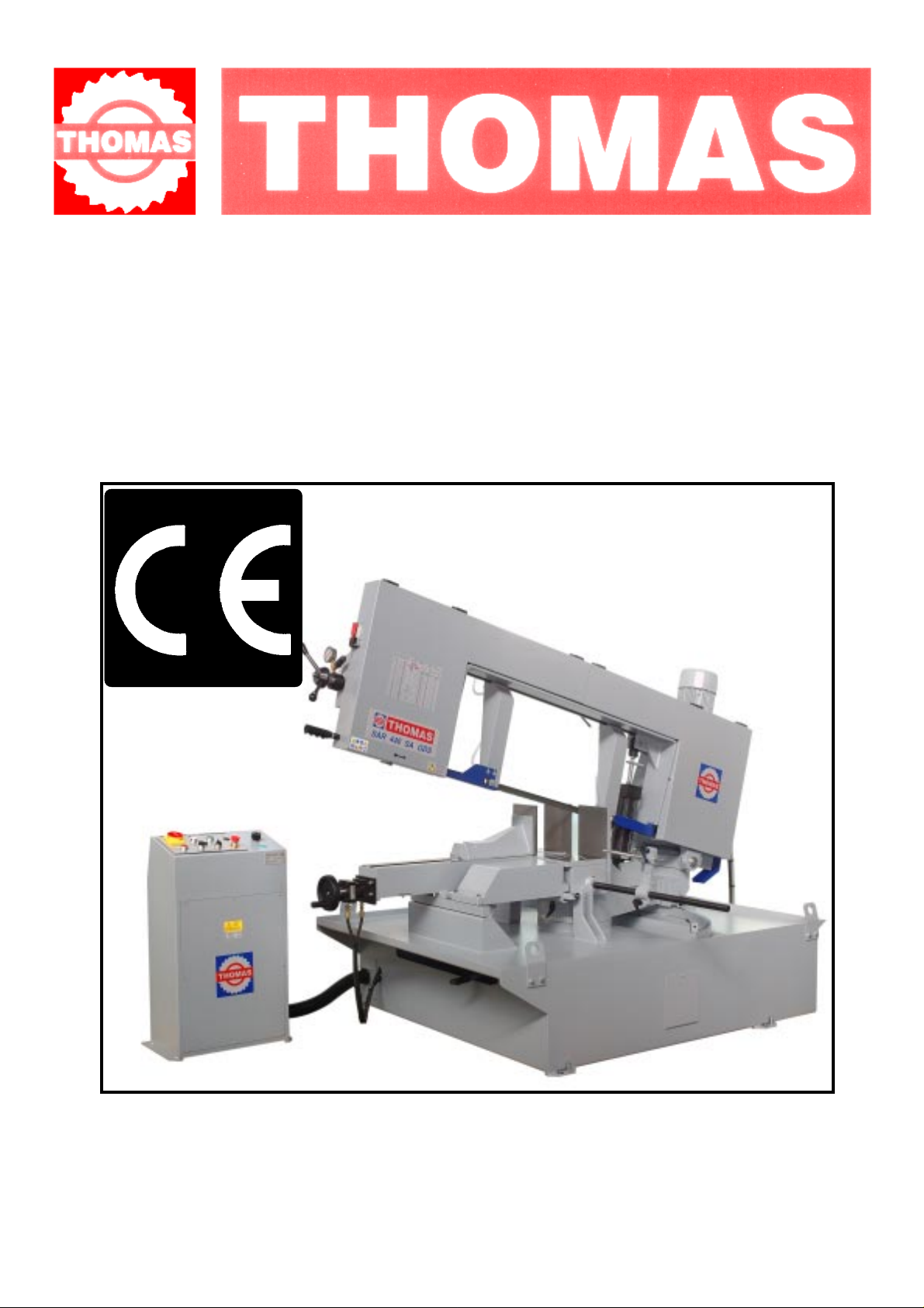
USE AND MAINTENANCE MANUAL
SAR 440 SA GDS
01/2006
THOMAS S.p.A. - Via Pasubio, 32 - 36033 Isola Vicentina (VI) - Telephone 0444 / 97.61.05 - Fax 0444 / 97.69.34
Registro Imprese n. 4272//VI116 REA n. 93906/Vicenza
Page 2

Contents
SAR 440 SA GDS
Contents........................................................................... " 2
Ordering spare parts........................................................" 2
Guarantee ........................................................................" 2
Machine certification and identification marking............." 3
CHAPTER 1
Reference to accident-prevention regulations .................." 4
1.1 - Advice for the operator ............................................. " 4
1.2 - Location of shields against accidental contact with
the tool..................................................................... " 4
1.3 - Electrical equipment according to European
Standard "CENELEC EN 60 204-1"............................ " 4
1.4 - Emergencies according to European Standard
"CENELEC EN 60 204-1" .........................................." 4
CHAPTER 2
Recommendations and advice for use .............................." 4
2.1 - Recommendations and advice for using the machine........ " 4
CHAPTER 3
Technical characteristics ................................................." 5
3.1 - Table of cutting capacity and technical details ............" 5
CHAPTER 4
Machine dimensions - Transport - Installation
Dismantling ...................................................................... " 5
4.1 - Machine dimensions ................................................. " 5
4.2 - Transport and handling of the machine ....................." 6
4.3 - Minimum requirements for the premises
housing the machine................................................. " 6
4.4 - Anchorage of standard machine ..............................." 6
4.5 - Instructions for electrical connection ........................." 6
4.6 - Instructions for assembly of the loose parts and
accessories .............................................................." 6
4.7 - Disactivating the machine ........................................." 6
4.8 - Dismantling .............................................................." 6
CHAPTER 5
Machine functional parts.................................................." 7
5.1 - Operating head or saw frame ...................................." 7
5.2 - Vice.........................................................................." 7
5.3 - B e d .......................................................................... " 7
CHAPTER 6
Description of the operating cycle ...................................." 8
6.1 - Starting up and cutting cycle ..................................... " 8
CHAPTER 7
Regulating the machine ...................................................." 9
7.1 - Blade tension assembly...........................................“ 10
7.2 - Blade guide blocks .................................................. “ 10
7.3 - Vice ......................................................................... “ 11
7.4 - Regulating the cutting angle .....................................“ 11
7.5 - Blade-cleaning brush ...............................................“ 11
7.6 - Regulating the height of the cut ................................ “ 11
7.7 - Regulating the cutting speed ...................................." 11
7.8 - Changing the blade .................................................." 12
CHAPTER 8
Routine and special maintenance................................. " 12
8.1 - Daily maintenance ..................................................." 12
8.2 - Weekly maintenance ..............................................." 12
8.3 - Monthly maintenance ..............................................." 12
8.4 - Six-monthly maintenance......................................... " 12
8.5 - Oils for lubricating coolant........................................ " 12
8.6 -Oil disposal ................................................................" 12
8.7 - Special maintenance................................................" 12
CHAPTER 9
Material classification and choice of tool ..................... " 13
9.1 - Definition of materials............................................... " 13
9.2 - Selecting blade ........................................................ " 13
9.3 - T eeth pitch ............................................................... " 13
9.4 - Cutting and advance speed ....................................." 14
9.5 - Blade running-in ....................................................... " 14
9.6 - Blade structure ........................................................" 14
9.7 - Blade type ............................................................... " 14
T eeth shape and angle............................................. " 14
Set..........................................................................." 15
9.7.1 - T a ble of recommended cutting parameters ................... " 15
CHAPTER 10
Machine components .................................................... " 16
10.1- List of spare parts .................................................... " 16
CHAPTER 11
Wiring diagrams ............................................................ " 21
Schema elettrico idraulico ............................................ " 23
CHAPTER 12
T roub leshooting ............................................................ " 24
12.1- Blade and cutting diagnosis ..................................... " 24
12.2- Electrical components diagnosis.............................. " 28
CHAPTER 13
Noise tests ..................................................................... " 28
Plates and labels............................................................ " 29
Ordering spare parts
- When ordering spare parts you must state:
MACHINE MODEL
SERIAL NUMBER
PART REFERENCE NUMBER
Without these references WE WILL NOT SUPPLY the spares. See point 10.1 - list of spare parts -
Guarantee
- The Company guarantees that the machine to which this manual refers has been designed and built to comply with safety regulations and
that it has been tested for functionality in the factory.
- The machine is guaranteed for 12 months: the guarantee does not cover the electric motors, electric components, pneumatic components
or any damage due to dropping or to bad machine management, the failure to observe maintenance standards or bad handling by the
operator.
- The buyer has only the right to replacement of the faulty parts, while transport and packing costs are at his expense.
- The serial number on the machine is a primary reference for the guarantee, for after-sales assistance and for identifying the machine for any
necessity.
2
Page 3
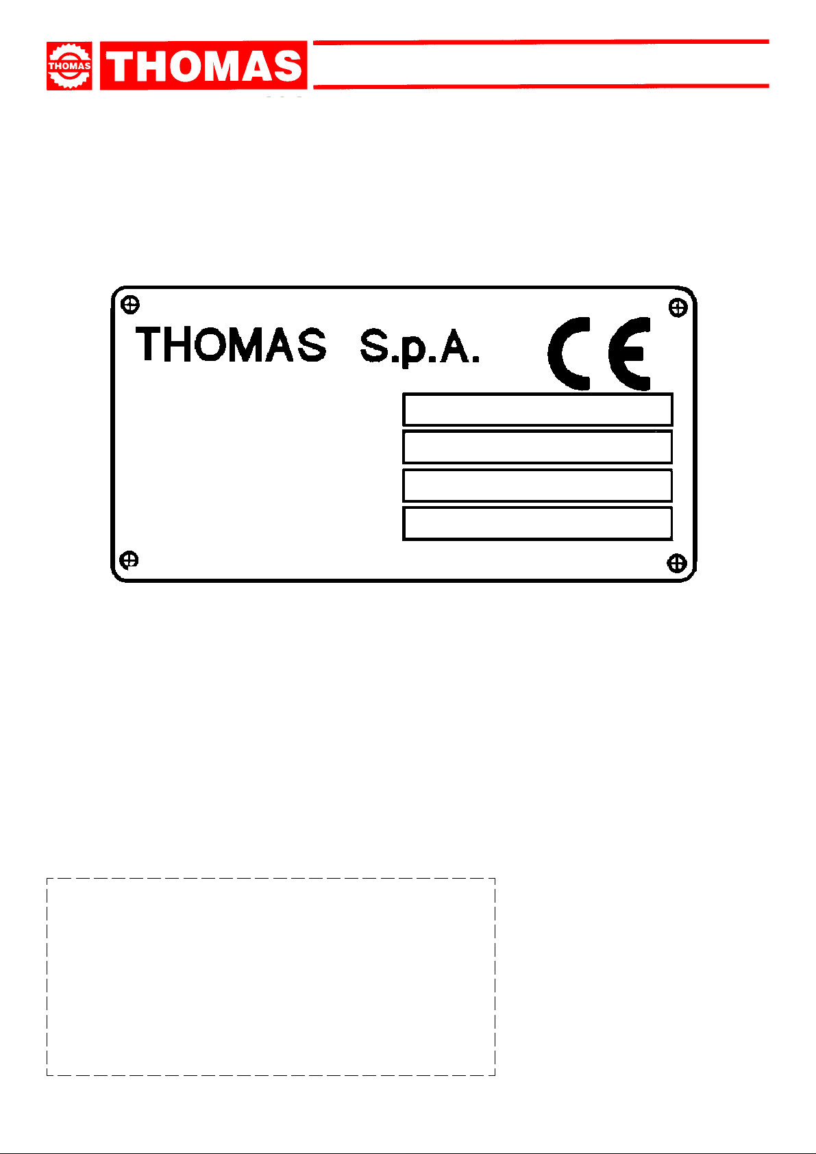
Machine certification and identification marking
MACHINE LABEL
via Pasubio, 32 36033 ISOLA VIC. - ITALIA
SAR 440 SA GDS
MODEL
TYP
SERIAL NUMBER
YEAR OF MANUFACTURE
SAR
440 SA GDS
(Space reserved for the NAME and STAMP of the DEALER and/or IMPORTER)
3
Page 4
SAR 440 SA GDS
REFERENCE TO ACCIDENT - PREVENTION REGULATIONS
1
This machine has been built to comply with the national and community accident-prevention regulations in force. Improper use
and/or tampering with the safety devices will relieve the manufacturer of all responsibility.
1.1 - Advice for the operator
- Check that the voltage indicated on the plate, normally fixed to the machine motor, is the same as the line voltage.
- Check the efficiency of your electric supply and earthing system; connect the power cable of the machine to the socket and the earth
lead yellow-green in colour) to the earthing system.
- When the saw frame is in suspend mode (up) the toothed blade must not move.
- Only the blade section used for cutting must be kept unprotected. Remove guarding by operating on the adjustable head.
- It is forbidden to work on the machine without its shields (these are all blue or grey in colour).
- Always disconnect the machine from the power socket before blade change or carrying out any maintenance job, even in the case
of abnormal machine operation.
- Always wear suitable eye protection.
- Never put your hands or arms into the cutting area while the machine is operating.
- Do not wear loose clothing with sleeves that are too long, gloves that are too big, bracelets, chains or any other object that could get
caught in the machine during operation; tie back long hair.
- Keep the area free of equipment, tools or any other object.
- Perform only one operation at a time and never have several objects in your hands at the same time. Keep your hands as clean as
possible.
- All internal and/or internal operations, maintenance or repairs, must be performed in a well-lit area or where there is sufficient light
from extra sources so as to avoid the risk of even slight accidents.
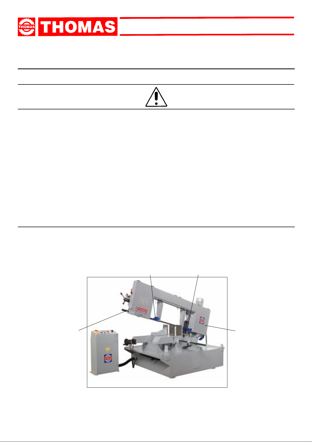
1.2 - Location of shields against accidental contact with the tool
- Blue or grey metal shield fixed frontally with screws to the fixed blade-guiding block ( Ref. A ).
- Blue or grey metal shield fastened on the front with screws onto the blade guide adjustable head to ensure maximum covering of
blade and piece to be cut ( Ref. B ).
- Grey metal guards fastened to the saw frame with knobs, protecting the blade driving flywheels ( Ref. C ).
B
C
A
C
4
Page 5
SAR 440 SA GDS
1.3 - Electrical equipment according to European Standard "CENELEC EN 60 204-1" which assimilates,
with some integrating modifications, the publication "IEC 204-1"
- The electrical equipment ensures protection against electric shock as a result of direct or indirect contact. The active parts of this
equipment are housed in a box to which access is limited by screws that can only be removed with a special tool; the parts are fed
with alternating current at low voltage (24 V). The equipment is protected against splashes of water and dust.
- Protection of the system against short circuits is ensured by means of rapid fuses and earthing; in the event of motor overload,
protection is provided by a thermal relay.
- In the event of a power cut, the specific start-up button must be reset.
- The machine has been tested in conformity with point 20 of EN 60204.
1.4 - Emergencies according to European Standard "CENELEC EN 60 204-1"
- In the event of incorrect operation or of danger conditions, the machine may be stopped immediately by pressing the red mushroom button.
- The casual or voluntary removal of the protection shield of the flywheels causes the stepping-in of a microswitch that automatically
stops all machine functions.
- In case blade breaks, the band tightening microswitch/pressure switch disconnects all machine.
NOTE:Resetting of machine operation after each emergency stop is achieved by reactivating the specific restart button.
RECOMMENDATIONS AND ADVICE FOR USE
2
2.1 - Recommendations and advice for using the machine
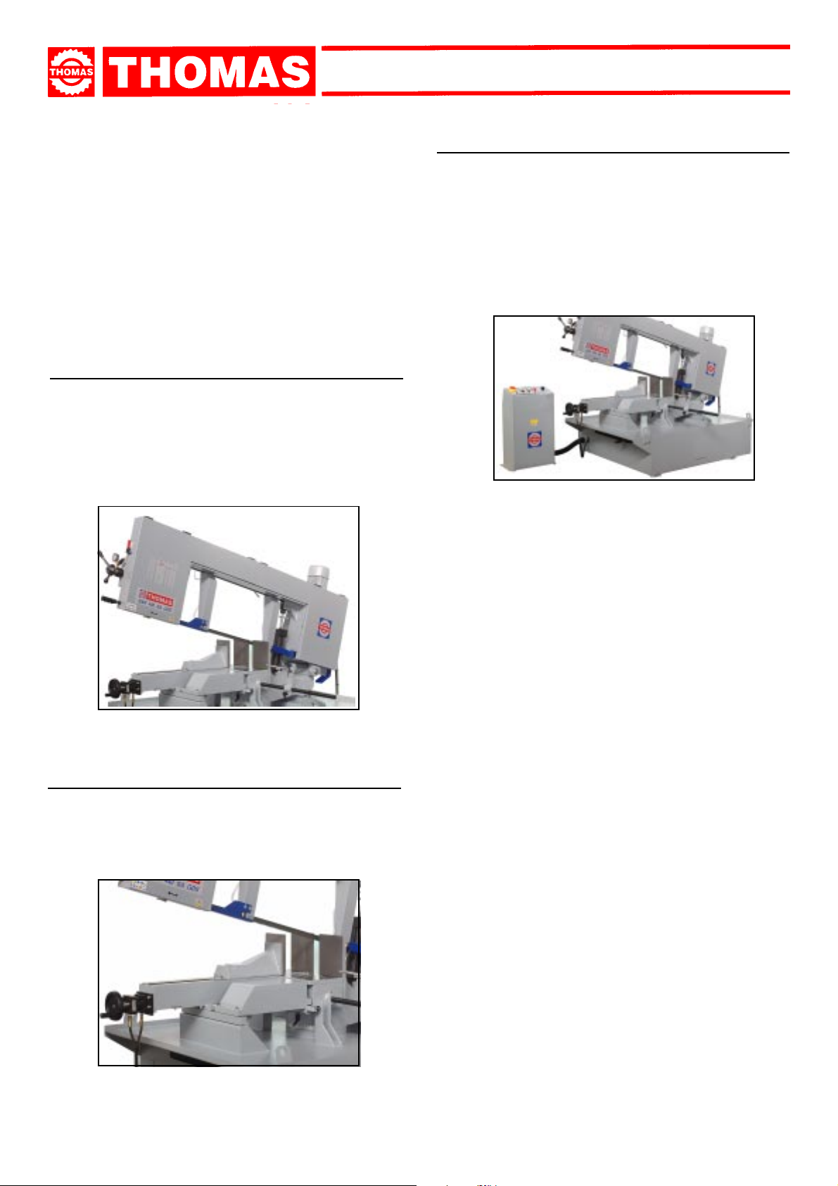
- The machine has been designed to cut metal building materials, with different shapes and profiles, used in workshops, turner’s
shops and general mechanical structural work.
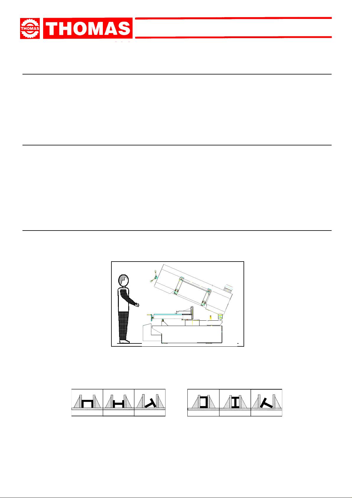
- Only one operator is needed to use the machine, that must stand as shown in the picture.
- Before starting each cutting operation, ensure that the part is firmly gripped in the vice and that the end is suitably supported.
These figures show examples of suitable clamping of different section bars, bearing in mind the cutting capacities of the machine in
order to achieve a good efficiency and blade durability.
- Do not use blades of a different size from those stated in the machine specifications.
- If the blade gets stuck in the cut, release the running button immediately, switch off the machine, open the vice slowly, remove the
part and check that the blade or its teeth are not broken. If they are broken, change the tool.
- Check saw frame return spring to ensure proper balancing.
- Before carrying out any repairs on the machine, consult the dealer or apply to THOMAS.
5
Page 6
SAR 440 SA GDS
TECHNICAL
3
CHARACTERISTICS
3.1 - Table of cutting capacity and technical details
0° 440 440 610 x 440
45° DX 440 440 500 x 230
45° SX 440 440 500 x 230
60° DX 320 300 320 x 245
60° SX 340 320 340 x 250
MACHINE DIMENSIONS
TRANSPORT
4
INSTALLATION
DISMANTLING
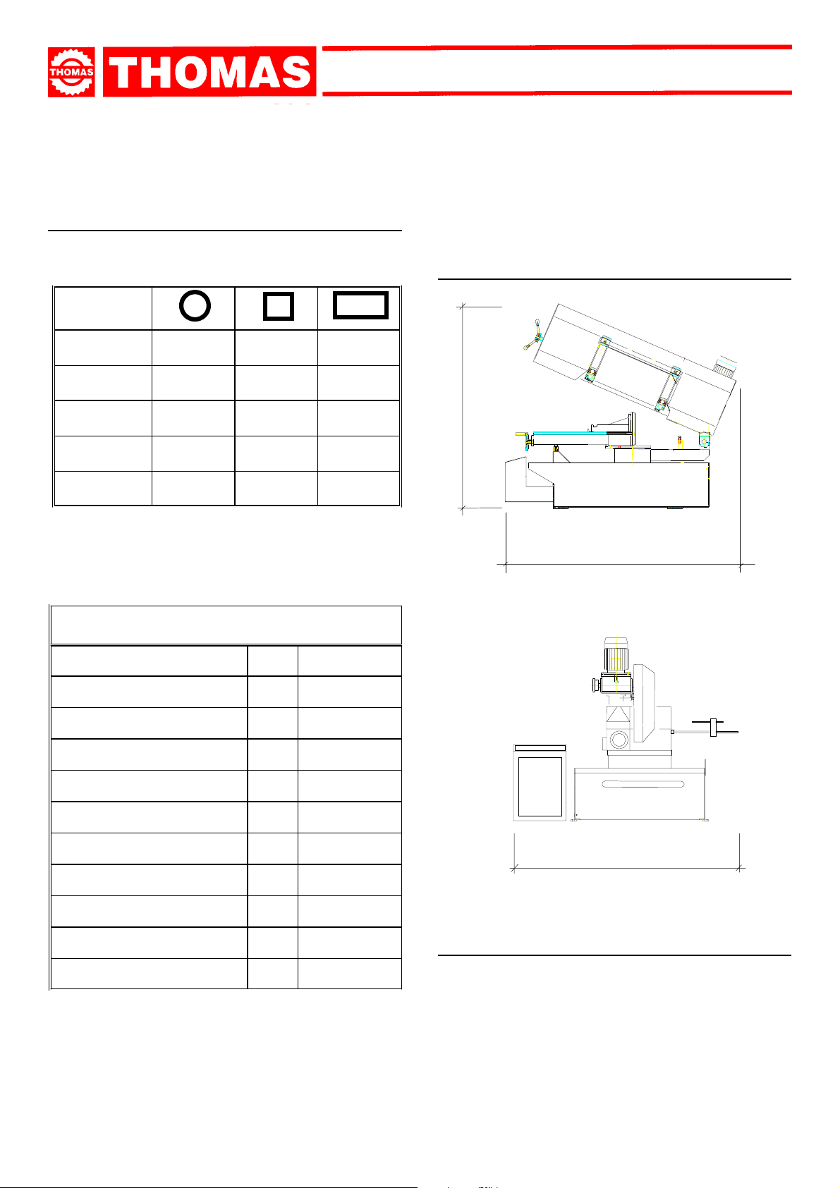
4.1 - Machine dimensions
2500
TE CHNICAL DATA
ELECTRIC MOTOR - 3-PHASE
HYDRA ULIC PUMP MOTOR
COOLANT PUMP MOTOR
FLYWHEEL Ø
BLADE DIMENSIONS
VARIABLE BLADE SPEED
VICE OPENING
SAW F RAME INCL INA TION
WORKING TA BLE HEIGHT
MA CHINE DIME NS IONS
kW 2,2
kW 1,1
kW 0,18
mm 455
mm 5200 x 34 x 1,1
m/min 28 ÷ 140
mm 615
°0
mm 750
mm 2500x 3000x2500
3000
2400
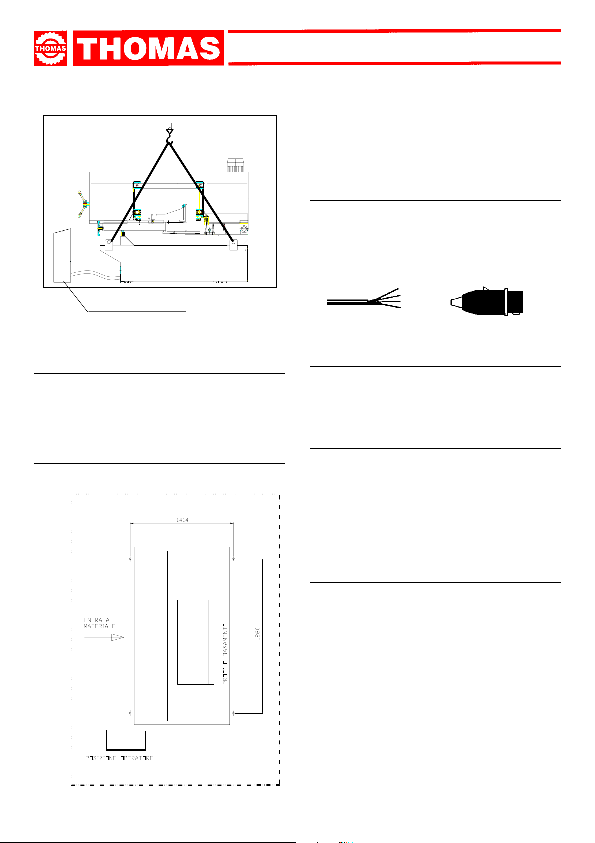
4.2 - Transport and handling of the machine
MACHINE WE IG HT
6
Kg 1570
In case of transportation in its own packing, use a fork-lift truck.
Sling the machine with special straps as illustrated making
sure that the control panel has been securely placed on the
machine base
Page 7
QUADRO ELETTRICO
SAR 440 SA GDS
- Position the machine on a firm cement floor, maintaining, at the
rear, a minimum distance of 1000 mm from the wall; anchor it to
the ground as shown in the diagram, using screws and expansion
plugs or tie rods sunk in cement, ensuring that it is sitting level.
4.5 - Instructions for electrical connection
- The machine is not provided with an electric plug, so the customer
must fit a suitable one for his own working conditions:
1 - WIRING DIAGRAM FOR 4-WIRE SYSTEM FOR THREE-
PHASE MACHINE - SOCKET FOR A 16A PLUG
R = L1
S = L2
T = L3
PE = GND
4.3 - Minimum requirements for the premises
housing the machine
- Mains voltage and frequency complying with the machine motor
characteristics.
- Environment temperature from -10 °C to +50 °C.
- Relative humidity not over 90%.
4.4 - Anchorage of standard machine
INGOMBRO OPERATIVO = mm 2400
INGOMBRO OPERATIVO = mm 3000
4.6 - Instructions for assembly of the loose parts and
accessories
Fit the components supplied as indicated in the photo:
- Mount the stock stop.
- Mount the coolant liquid holder.
4.7 - Disactivating the machine
- If the sawing machine is to be out of use for a long period, it is
advisable to proceed as follows:
1) detach the plug from the electric supply panel
2) loosen blade
3)empty the coolant tank
4)carefully clean and grease the machine
5)if necessary, co ver the machine .
4.8 - Dismantling
(because of deterioration and/or obsolescence)
General rules
If the machine is to be permanently demolished and/or scrapped,
divide the material to be disposed of according to type and composition, as follows:
1) Cast iron or ferrous materials, composed of
ondary raw materials, so they may be taken to an iron foundry
for re-smelting after having removed the contents (classified in
point 3);
2) electrical components, including the cable and electronic ma-terial
(magnetic cards, etc.), fall within the category of material classified as being assimilable to urban waste according to the laws of
the European community, so they may be set aside for collection
by the public waste disposal service;
3) old mineral and synthetic and/or mixed oils, emulsified oils and
greases are special refuse, so they must be collected, transported
and subsequently disposed of by the old oil disposal service.
metal alone, are sec-
NOTE:since standards and legislation concerning refuse in gen-
7
Page 8
SAR 440 SA GDS
eral is in a state of continuous evolution and therefore
subject to changes and variations, the user must keep
informed of the regulations in force at the time of disposing
of the machine tool, as these may differ from those
described above, which are to be considered as a general
guide line.
MACHINE FUNCTIONAL
5
PARTS
5.1 - Operating head or saw frame
- Machine part consisting of the members that transfer the motion
(gearmotor, flywheels), the tightening/guiding (blade guide arms,
blade tightening slide) and the tool lowering control.
5.3 - Bed
- Structure supporting the HEAD OR SAW FRAME, the VICE, the
SWIVEL DEVICE with relative locking system, the ELECTRICALS,
the BAR STOP and housing the coolant TANK for cut and pump.
5.2 - Vice
- Hydrailic locking system for cutting material. This de vice allows
for the quick shifting of the vice and the possibility to cut
inclinations to the left and right.
8
Page 9
SAR 440 SA GDS
DESCRIPTION OF THE
6
OPERATING CYCLE
Before operating, all the main organs of the machine must be
set in optimum conditions (see the chapter on “Regulating the
machine”).
6.1 - Getting started
DESCRIPTION OF THE CUTTING PROCESS:
- Start the cutting cycle
- Automatic closure of the vice;
- Lowering of the sawframe ( blade );
- Lifting of the sawframe ( using selector );
- Opening of the vice.
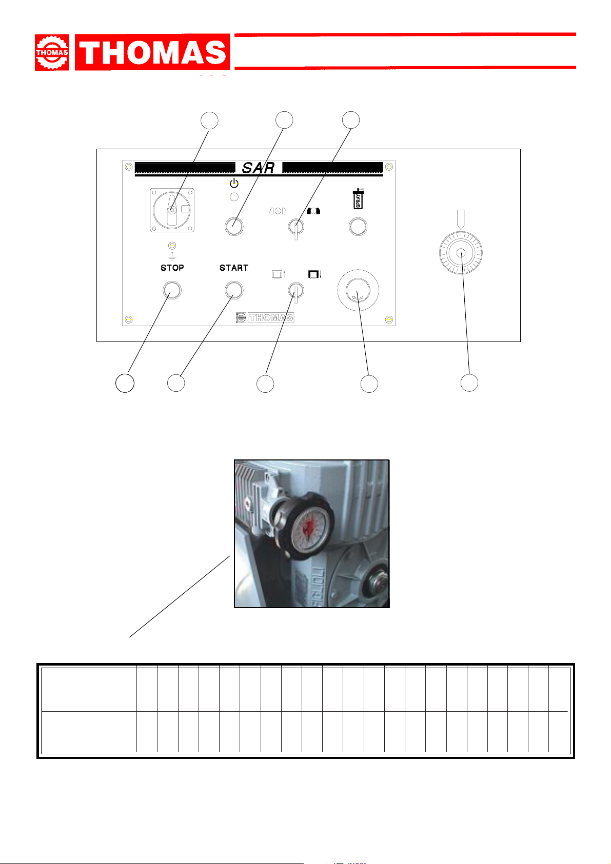
PRELIMINARY OPERATIONS:
- Ensure that the machine is not on emergency stop; in which case
free the red, mushroom shaped, button ( 1 ) on the panel of commands.
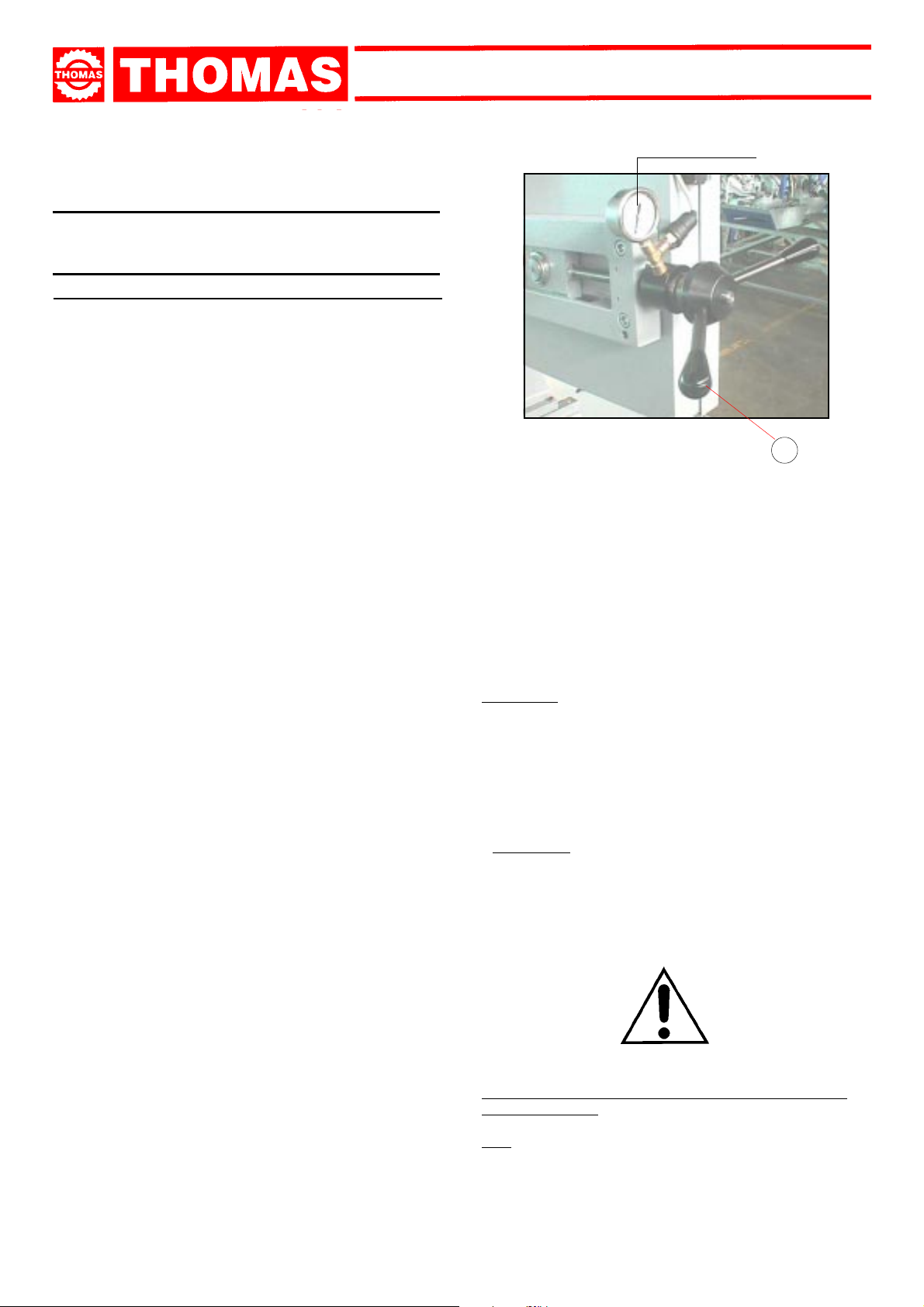
- Rotate the blade tension handwheel ( 8 ) until the blade tension
pressure reaches 160 Bars.
- Rotate the main switch ( 2 ) in position 1.
- Press the illuminated button ( 3 ) and ensure that the relative
light is lit.
- Rotate the selector ( 5 ) to activate the lifting of the sawframe.
N.B.: if the lifting process does not occur, invert the electric
alimentation phase ( this operation is only to be done during installation ).
Service pressure of the hydraulic unit should be approx. 50
BAR.
WARNING: always ensure that the vice is positioned to the
extreme left or right of the counter vice to avoid accidental
contact with the structure of the sawframe.
- Turn selector ( 9 ) to open the vice.
160 BAR
8
- Activate the hand wheel of the gear and set the speed control
to suit the characteristics of the material to be cut. ( do not
regulate when the motor is off ).
To regulate the desired speed refer to the plaque .
- In case of a wrong manoeuvre or to stop the cutting cycle,
press the STOP button ( 10 ).
- At the end of the cutting cycle, the sawframe will stop in the
inferior position. Rotate the selector ( 5 ) to activate the lifting of
the sawframe.
- Turn selector ( 9 ) to open the vice.
ATTENTION:
- The cutting cycle can be executed even if the selector ( 9 ) has
been switched for the open vice.
In fact, as you press START ( 3 ) the vice will close automatically .
To open the vice again you will have to turn the selector ( 9 )
first to close the vice and then to open the vice.
- Once the cut has been executed the hydraulic pump will keep
running for 20 seconds.
- Position the vice according to the dimension of the material to
cut.
- Put the material to be cut in the vice, and approach the vice
jaw up to 3 - 4 mm with the handwheel.
- Ensuring that the latch is in place on the rack.
- Load the material to cut at the required cutting length and turn
the selector ( 9 ) to lock the material in the vice.
- Bring the mobile blade guiding arm as close as possible to
the object to be cut.
- Ensure that the cutting index correspond with the inclination
desired and that the device is blocked.
- Before starting the cutting process, it is advisable to advance
the blade to more or less 10 mm from the object to be cut,
pressing, if necessary, selector ( 5 ).
- Press regulator ( 6 ) to the ideal cutting speed to suit the
characteristics of the material. It is recommend that one always
start off slowly, increasing the speed if necessary.
- Press button ( 4 ) to initiate the cutting cycle: control that the
blade turns in the correct direction and that the cooling liquid
flows sufficiently.
ATTENTION: Soon after the automatic shut off of the hydraulic
pump, press the button ( 4 ) to open the vice automatically if
the selector ( 9 ) was switched to vice open during the cutting
phase.
Note: It is recommend not to use the saw to its maximum
capacity for the first 50 working hours.
It is absolutely forbidden to approach the hands to
the cutting area.
Note: for a proper lubrication and cooling during the cut, we
recommend to use a mixture of 9 parts of water and one of oil.
9
Page 10
SAR 440 SA GDS
10
2
1
4
3
5
9
1
6
10
nim/m
F
EROTAIRAVONITNALOV
DNAH-ROTAIRAV
LEEHW
°N.SOP
DEEPSGNITTUC
89 01112131415161718191021222324252627282
OILGATID'ATICOLEV
5.72235.635.14641565165.66275.77389859101701311021721331041
Page 11

SAR 440 SA GDS
- the CUTTING SPEED and the TYPE of BLADE - combined
with a suitable lowering of saw frame - are of decisive importance for cutting quality and for machine performance (for
further details on this topic, see below in the chapter on “Mate-
rial classification and blade selection”).
- When starting to cut with a new blade, in order to safeguard its
life and efficiency, the first two or three cuts must be made
while exerting a slight pressure on the part, so that the time
taken to cut is about double the normal time (see below in the
chapter on “Material classification and blade selection” in the
section on
- Press the red emergency button ( 1 ) when there are conditions of
danger or malfunctions in general, so as to stop machine operation immediately.
CUTTING DIRECTION
Blade running-in
).
7.2 - Blade-guide head
Blade guiding is obtained by means of plates which are regulated
during the testing phase according to blade thickness.
B
A
A
REGULATING
7
THE MACHINE
7.1 - Blade tension assembly
The ideal blade tension is obtained by rotating the hand wheel belt
tensioner until the blade tension pressure reaches 160 Bars
otherwise the saw will not operate.
N.B.: when the saw is not in use it is recommend to loosen the
blade tension.
It is always recommend to use the blade sizes suggested in
this manual.
160 BAR
8
AB
C
When replacing a blade, ensure that the belts are 1,1 mm thick as
the guiding blade pads have been adjusted to this size. If using
different size toothed belts, it will be necessary to proceed with a
new registration as follows:
- Loosen the screws ( B ) and loosen dowels (A ) widening the
passage between the plates.
- Loosen the dowels ( C ) and rotate the pins to widen the passage
between the bearings.
- Mount the new blade and rotate the hand wheel belt tensioner
until the relative dip-switch is activated.
- Tighten the dowels ( A ) and then loosen them to allow a play of
0,04 mm to ensure the smooth running of the blade and fasten
the screws ( B ).
- Rotate the pins until the bearings rest on the blade and block the
screws ( C ).
- Ensure that between the blade and the superior bearings there
are 0,2 - 0,3 mm of play; if necessary, loosen the screws ( D )
that block the heads and execute the necessary registration.
11
Page 12

SAR 440 SA GDS
7.3 - Vice
-- The rapid advancement of the vice to the object to be cut is
obtained by manually moving the vice and lifting the latch ( F ).
Before blocking the object to be cut with the hand wheel check
that the latch is gripped to the rack.
- The vice unit can be positioned to the left or right of the blade.
Ensure that this positioning has been executed correctly in order
to avoid irreparab le damage to the saw .
- It is recommended to keep the vice guide and ribbon clean and
oiled at all times.
F
7.5 - Blade-cleaning brush
Ideal for the cleaning of the blade during its cutting cycle.
Periodically check the integrity of the brush and if necessary
proceed to an ulterior regulation to guarantee cleansing of
the blade.
7.6 - Regulating the height of the cut
It is an accessory that permits the execution of lifting and/or nearing of the arch.
- Operate the selector button ( H ) to move the arch up and
down to the desired position.
1
H
6
7.4 - Regulating the cutting angle
- Lift the sawframe.
- Operate the Lever ( G ) to release the rotation of the device.
- Rotate the sawframe to the desired angle referring to the
graduated sector.
- Tighten the lever ( G ) to block the device from rotating.
7.7 - Regulating the cutting speed
Regulation of the cutting speed can only be done with the motorbelt in motion.
T o change the running speed, adjust with hand wheel and refer to
the plaque.
V
TABELLA LUBRIFICANTI
COMPONENTE
PART.
LUBRIFICANTE
OIL TYPE
QUANTITA'
KG
12
G
INDICE
RIDUT T ORE
REDUCT OR
VARIATORE
VARIATOR
SHELL
TIVELA S320
SHELL
DO NAX T A
1,6
1,2
Page 13

SAR 440 SA GDS
BEFORE PERFORMING THE FOLLOWING OPERATIONS,
THE ELECTRIC POWER SUPPLY AND THE POWER CABLE
MUST BE COMPLETELY DISCONNECTED.
7.8 – Replacing the blade
- Lift the sawframe in upright position.
- Loosen the blade with the hand wheel, remove the shield of the
mobile blade guide and the shield of the belt cleaning brush.
- Open the posterior and anterior carter flywheels and extract the
old blade from the flywheels and from the blade guide blocks.
- Insert the new blade inserting it between the plaques and then
on the flywheel holder, taking note of the direction of the teeth in
respect to the direction of the cut (refer to diagram below).
- Replace the tension of the blade checking that it is housed
perfectly within the flywheels.
- Re-assemble the shields of the mobile guide blade and of the
belt cleaning brush and close the carter flywheels cover, checking
that the safety dip-switch is activated otherwise the machine will
not operate when it is switched on.
WARNING: alwa ys use blades having dimensions spcified
in this manual and for which the blade guide heads have
been set: otherwise, see chapter on "Description of the
operating cycle" in the section Starting-up..
CUTTING DIRECTION
8.2 - Weekl y maintenance
- More accurate general cleaning of the machine to remove shavings, especially from the lubricant fluid tank.
- Removal of pump from its housing, cleaning of the suction filter
and suction zone.
- Clean the filter of the pump suction head and the suction
area.
- Cleaning with compressed air of blade guide arms (guide bearings, pads and drain hole of the lubricating cooling).
- Cleaning flywheel housings and blade sliding surfaces on flywheels.
- Check condition of the blade cleaning brushes.
- Greasing of motor flywheel bearings.
8.3 - Monthly maintenance
- Check the tightening of the motor flywheel screws.
- Check that the blade guide bearings on arms are perfect running
condition.
- Check the tightening of the screws of the gearmotor, pump and
accident protection guarding.
8.4 - Six-monthly maintenance
REDUCTION UNIT
-
we suggest to make the first oil replacement after about 300
working hours and wash internal parts carefully.
Use synthetic oil SHELL TIVELA OIL 320 type or equiv alent.
-
The following oil replacement should be made after about 2000
working hours.
V ARIATOR UNIT
-
Make the oil replacement after about 2000 working hours using
the SHELL DONAX TA type or equivalent.
PROBABLE REPLACEMENT OF OTHER PARTS –
REDUCTION GEAR OR SPEED CONTROL, MOTOR PUMP
AND ELECTRICAL COMPONENTS – TO BE EXECUTED BY
SPECIALISED AND COMPETENT PERSONNEL.
ROUTINE
AND SPECIAL
8
MAINTENANCE
THE MAINTENANCE JOBS ARE LISTED BELOW, DIVIDED INTO
DAILY, WEEKLY, MONTHLY AND SIX-MONTHLY INTERVALS. IF
THE FOLLOWING OPERATIONS ARE NEGLECTED, THE RESULT
WILL BE PREMATURE WEAR OF THE MACHINE AND POOR
PERFORMANCE.
8.1 - Daily maintenance
- General cleaning of the machine to remove accumulated shavings.
- Clean the lubricating coolant drain hole to avoid excess fluid.
- Top up the level of lubricating coolant.
- Check blade for wear.
- Rise of saw frame to top position and partial slackening of the
blade to avoid useless yield stress.
- Check functionality of the shields and emergency stops.
WARNING : absolutely do not mix synthetic oil and mineral oil.
Replace the oil in the hydraulic unit ad least once a year using
SHELL HYDRAULIC OIL 32 type or equiv alent.
- The saw with the ascending arch device, a complete oil change
is advisable once a year using SHELL HYDRAULIC OIL 32 or
similar.
- Continuity test of the equipotential protection circuit.
8.5 - Oils for lubricating coolant
Considering the vast range of products on the market, the user
can choose the one most suited to his own requirements, using as
reference the type SHELL LUTEM OIL ECO.
THE MINIMUM PERCENTAGE OF OIL DILUTED IN W ATER IS
8 - 10 %.
8.6 - Oil disposal
The disposal of these products is controlled by strict regulations.
Please see the Chapter on “Machine dimensions - Transport - In-
stallation” in the section on
Dismantling
.
8.7 - Special maintenance
Special maintenance operations must be carried out by skilled personnel.
However, we advise contacting THOMAS or their dealer and/or importer. Also the reset of protective and safety equipment and devices, of the reducer, the motor, the motor pump and electric components is to be considered extraordinary maintenance.
13
Page 14

SAR 440 SA GDS
MATERIAL
CLASSIFICATION AND
9
CHOICE OF TOOL
Since the aim is to obtain excellent cutting quality, the various
parameters such as hardness of the material, shape and thick-
ness, transverse cutting section of the part to be cut, selec-
tion of the type of cutting blade, cutting speed and control of
saw frame lowering.These specifications must therefore be har-
moniously combined in a single operating condition according to
practical considerations and common sense, so as to achieve
an optimum condition that does not require countless operations to prepare the machine when there are many variations in
the job to be performed.The various problems that crop up from
time to time will be solved more easily if the operator has a good
knoledge of these specifications.
WE THEREFORE RECOMMEND YOU TO ALWAYS USE
GENUINE SP ARE BLADES THAT GUARANTEE SUPERIOR
QUALITY AND PERFORMANCE.
9.1 - Definition of materials
The table at the foot of the page lists the characteristics of the materials to be cut, so as to choose the right tool to use.
9.2 - Selecting blade
be cut, according to these criteria:
- parts with a thin and/or variable section such as profiles, pipes
and plate, need close toothing, so that the number of teeth used
simultaneously in cutting is from 3 to 6;
- parts with large transverse sections and solid sections need widely
spaced toothing to allow for the greater volume of the shavings
and better tooth penetration;
- parts made of soft material or plastic (light alloys, mild bronze,
teflon, wood, etc.) also require widely spaced toothing;
- pieces cut in bundles require combo tooth design.
9.3 - Teeth pitch
As already stated, this depends on the following factors:
- hardness of the material
- dimensions of the section
- thickness of the wall.
BLADE TEETH SELECTION TABLE
THICKNESS MM
TILL 1.5 14 10/14
FROM 1 TO 2 8 8/12
FROM 2 TO 3 6 6/10
FROM 3 TO 5 6 5/8
FROM 4 TO 6 6 4/6
MORE THAN 6 4 4/6
Z CONTINUOUS
TOOTH DESIGN
Z COMBO
TOOTH DESIGN
First of all the pitch of the teeth must be chosen, in the other words,
the number of teeth per inch (25,4 mm) suitable for thematerial to
TYPES OF STEEL CHARACTERISTICS
USE
Construction
steels
Carbon
steels
Spring
steels
Alloyed steels for
hardening and
tempering and for
nitriding
Alloyed
casehardening
steels
Alloyed for
bearings
Tool steel
Stainless
steels
Copper alloys
Special brass
Bronze
Cast iron
I
UNI
Fe360
Fe430
Fe510
C20
C40
C50
C60
50CrV4
60SiCr8
35CrMo4
39NiCrMo4
41CrAlMo7
18NiCrMo7
20NiCrMo2
100Cr6 100Cr6 100C6 534 A 99 52100 207 95 690÷980
52NiCrMoKU
C100KU
X210Cr13KU
58SiMo8KU
X12Cr13
X5CrNi1810
X8CrNi1910
X8CrNiMo1713
Aluminium copper alloy G-CuAl11Fe4Ni4 UNI 5275
Special manganese/silicon brass G-CuZn36Si1Pb1 UNI5038
Manganese bronze SAE43 - SAE430
Phosphor bronze G-CuSn12 UNI 7013/2a
Gray pig iron G25
Spheroidal graphite cast iron GS600
Malleable cast iron W40-05
56NiCrMoV7C100K
D
DIN
St37
St44
St52
CK20
CK40
CK50
CK60
50CrV4
60SiCr7
34CrMo4
36CrNiMo4
41CrAlMo7
----
21NiCrMo2
C100W1
X210Cr12
----
4001
4301
----
4401
F
AF NOR
E24
E28
E36
XC20
XC42H1
----
XC55
50CV4
----
35CD4
39NCD4
40CADG12
20NCD7
20NCD2
----
----
Z200C12
Y60SC7
----
Z5CN18.09
----
Z6CDN17.12
GB
SB
---43
50
060 A 20
060 A 40
----
060 A 62
735 A 50
----
708 A 37
----
905 M 39
En 325
805 H 20
----
BS 1
BD2-BD3
----
----
304 C 12
----
316 S 16
USA
AISI-SAE
----
----
---1020
1040
1050
1060
6150
9262
4135
9840
---4320
4315
----
S-1
D6-D3
S5
410
304
----
316
S = THICKNESS
Hardness
BRINELL
HB
116
148
180
198
198
202
202
207
224
220
228
232
232
224
244
212
252
244
202
202
202
202
220
140
120
100
212
232
222
Hardness
ROCKWELL
HRB
67
80
88
93
93
94
94
95
98
98
99
100
100
98
102
96
103
102
94
94
94
94
98
77
69
56,5
96
100
98
R=N/mm²
360÷480
430÷560
510÷660
540÷690
700÷840
760÷900
830÷980
1140÷1330
1220÷1400
780÷930
880÷1080
930÷1130
760÷1030
690÷980
800÷1030
710÷980
820÷1060
800÷1030
670÷885
590÷685
540÷685
490÷685
620÷685
375÷440
320÷410
265÷314
245
600
420
14
Page 15

SAR 440 SA GDS
SOLID Ø OR L MM
TILL 30 8
FROM 30 TO 60 6
FROM 40 TO 80 4 4/6
MORE THAN 90 3 3/4
Z CONTINUOUS
TOOTH DESIGN
Ø = DIAMETER L = WIDTH
Z COMBO
TOOTH DESIGN
5/8
4/6
9.4 - Cutting and advance speed
The cutting speed (m/min) and the advance speed (cm2/min = area
travelled by the disk teeth when removing shavings) are limited by
the development of heat close to the tips of the teeth.
- The cutting speed is subordinate to the resistance of the material
(R = N/mm
widest section.
- Too high an advance speed (= lowering of the saw frame) tends to
cause the disk to deviate from the ideal cutting path, producing
non rectilinear cuts on both the vertical and the horizontal plane.
The best combination of these two parameters can be seen directly
examining the chips.
Long spiral-shaped chips indicate ideal cutting.
2
), to its hardness (HRC) and to the dimensions of the
9.7 - Blade type
They differ essentially in their constructive characteristics, such as:
- shape and cutting angle of tooth
- pitch
- set
Shape and angle of tooth
REGULAR TOOTH: 0° rake and constant pitch.
Most common form for transversal or inclined cutting of solid small
and average cross-sections or pipes, in laminated mild steel and
grey iron or general metal.
POSITIVE RAKE TOOTH: 9° - 10° positive rake and constant pitch.
positive
Particular use for crosswise or inclined cuts in solid sections or large
pipes, but above all harder materials (highly alloyed and stainless
steels, special bronze and forge pig).
Very fine or pulverized chips indicate lack of
feed and/or cutting pressure.
Thick and/or blue chips indicate overload of
the blade.
9.5 - Blade running-in
When cutting for the first time, it is good practice to run in the
tool making a series of cuts at a low advance speed
(= 30-35 cm
to the cutting capacity and solid section of normal steel with R =
410-510 N/mm
2
/min on material of average dimensions with respect
2
), generously spraying the cutting area with lu-
bricating coolant.
9.6 - Blade structure
Bi-metal blades are the most commonly used. They consist in a silicon-steel blade backing with electron beam or laser welded high speed
steel (HHS) cutting edge. The type of stocks are classified in M2,
M42, M51 and differ from each other because of their major hardness due to the increasing percentage of Cobalt (Co) and molybdenum (Mo) contained in the metal alloy.
COMBO TOOTH: pitch varies between teeth and consequently varying teeth size and varying gullet depths. Pitch varies between teeth
which ensures a smoother, quieter cut and longer blade life owing to
the lack of vibration.
Another advantage offered in the use of this type of blade in the fact
that with an only blade it is possible to cut a wide range of different
distance between teeth
materials in size and type.
COMBO TOOTH: 9° - 10° positive rake.
positive
This type of blade is the most suitable for the cutting of section bars
and large and thick pipes as well as for the cutting of solid bars at
maximum machine capacity. Available pitches: 3-4/4-6.
15
Page 16

SAR 440 SA GDS
Set
Saw teeth bent out of the plane of the saw body, resulting in a wide
cut in the workpiece.
REGULAR OR RAKER SET: Cutting teeth right and left, alternated
by a straight tooth.
Of general use for materials with dimensions superior to 5 mm. Used
for the cutting of steel, castings and hard nonferrous materials.
WAVY SET: Set in smooth waves.
This set is associated with very fine teeth and it is mainly used for
9.7.1 - RECOMMENDED CUTTING PARAMETERS
the cutting of pipes and thin section bars (from 1 to 3 mm).
ALTERNATE SET (IN GROUPS): Groups of cutting teeth right and
left, alternated by a straight tooth.
This set is associated with very fine teeth and it is used for extremely
thin materials (less than 1 mm).
ALTERNATE SET (INDIVIDUAL TEETH): Cutting teeth right and left.
This set is used for the cutting of nonferrous soft materials, plastics
and wood.
STEEL C UTTING SPEED LUBRICATION
CONSTRUCTION 60/80 EMULSIFIABLE OIL
CEMENTATION 40/50 EMULSIFIABLE OIL
CARBON STEEL 40/60 EMULSIFIABLE OIL
HARDENING A ND TE MPE RING 40/50 EMULSIFIABLE OIL
BEARINGS 40/60 EMULSIFIABLE OIL
SPRINGS 40/60 EMULSIFIABLE OIL
FOR TOOLS 30/40 EMULSIFIABLE OIL
FOR VALVES 35/50 EMULSIFIABLE OIL
STAINLESS STEEL 30/40 EMULSIFIABLE OIL
SPHEROIDAL GRAPHITE 20/40 EMULSIFIABLE OIL
CAST IRON 40/60 EMULSIFIABLE OIL
16
ALUMINIUM 80/600 KEROSENE
BRONZE 70/120 EMULSIFIABLE OIL
HARD BRONZE 30/60 EMULSIFIABLE OIL
BRASS 70/350 EMULSIFIABLE OIL
COPPER 50/720 EMULSIFIABLE OIL
Page 17

SAR 440 SA GDS
10
MACHINE COMPONENTS
10.1 - List of spare parts
REFERENCE N° DENOMINATION
1 Bedframe
2 Electric box
3 Electric parts housing guard
4 Revolving arm lock lever
5 Arm lock bush
6 Machine hoisting hook
7 Lateral guard
8 Stroke-end stop
9 Adjustable bracket
10 Refrigeranting liquid tank
11 Electropump
12 Bar stop body
13 Bar stop push rod
14 Bar stop rod
15 Revolving arm pin
16 Countervice pin
17 Revolving arm
18 Bearing 32008 X
19 Bushing
20 Screw
21 Hinge pin protection
22 Bearing 32008 X
23 Hinge pin spacer
24 Hinge pin
25 Ring nut guk M 40x1,5
26 Countervice r.h. ja w
27 Countervice l.h. jaw
28 Interchangeable plate
29 Countervice
30 Countervice anterior guard
31 Pieces support
32
33 Vice support
34 Rack
35 Rack support
36 Vice
37 Vice screw
38 Handwheel
39 Pin
40 Pawl
41 Vice jaw
42 Crucible
43 Ring NILOS 32008 XAV
REFERENCE N° DENOMINATION
44 Bearing fork
45 Bearing SKF NATV 17 PPI
46 Pin
47 Bearing protection
48 Hydraulic vice cilinder
49 Hinge pin support
50 Sheath
51 Saw frame cylinder support
52 Bush
53 Pin
54 Handle
17
Page 18

SAR 440 SA GDS
REFERENCE N° DENOMINATION
60 Sawframe
61 Electric motor
62 Speed variator
63 Speed variator handwheel
64 Ring nut guk M 40x1,5
65 Speed reducer
66 Spacer
67
68 Cylinder joint
69 Cylinder superior pin
70 Microswitch
71 Plate
72 Plate
73 Sawframe cylinder
74
75 Adjustable screw
76 transmission flywheel pin
77 Ring nut guk M 45x1,5
78 Blade tightening slide
79
80
81 Handle
82 Blade tightening handwheel
pin
83 Pin
84 Blade tightening Cylinder
85 Bracket
86 Ring NILOS 32209 XAV
87 Bearing 32209 XAV
88
89 T ransmission flywheel
90 Ring nut guk M 45 x 1,5
91 Bearing 3309 2RS
92 Ring NILOS 3309 AV
93 Bearing protection
94 Motor flywheel shaft
95 Motor flywheel
96 Cone clamping
EUROCONIC
97 Blade guide protection
98 Microswitch
99 R.h Flywheel protection
100 L.h. Flywheel protection
101 Blade guide arm guide
10 2 L.h. adjustable blade guide
arm
10 3 R.h. adjustable blade guide
arm
104 Hand lever
105
106 Additional protection
REFERENCE N° DENOMINATION
107 Spacer
108 Bearing 51204
109 Spring washer
110 Manometer
11 1 Pressure switch
112 Rear crucible
113
11 4 Blade guide bearing pin
11 5 Bearing 6200 2RS
11 6 Ring seeger Ø 10
11 7 Upper blade guide pad
11 8 Lateral blade guide pad
119 Hinge
120 Middle protection
121 Brush
12 2 Brush support
12 3 Bearing 626 2RS
12 4 Brush ring
125 Blade protection
126 Auxiliary blade protection
127
130 Distributor block
131 Coupling
132 Cooling liquid cock
133
134 Flexible tube
135 Handgripp
18
Page 19

10
SAR 440 SA GDS
42
6
53
52
51
21
49
22
18
25
20
19
24
43
27
26
43
23
44
47
28
17
45
46
14
11
13
29
16
15
12
30
7
8
8
9
54
31
34
35
6
5
4
1
50
2
33
41
36
37
39
3
48
38
19
Page 20

20
81
82
83
109
108
110
84
78
77
107
ZOOM - 2
133
131
76
111
75
85
130
86
132
72
87
131
70
73
98
71
134
68
69
64
63
65
66
61
62
101
60
98
91
93
92
94
112
95
96
SAR 440 SA GDS
135
89
87
86
90
120
100
Page 21

104
102
104
103
124
SAR 440 SA GDS
126
125
97
115
114
116
ZOOM 1
117
118
106
118
117
123
ZOOM 2
122
121
114
115
116
21
Page 22

SAR 440 SA GDS
KEY:
401 Main switch
402 Arch movement selector
403 Emergency switch
404 STOP button
405 Regulator arch descent
406 On-line button
407 Start button
408 Vice selector
KEY:
401
404
406
1
407 402
408 405
403
410 Transformer
411 Fuse cartridge
412 Relay ( Kb )
413 Remote switch
414 Thermal motor
415 Remote switch
416 Timer
417 Thermal motor
KEY:
421 Motor gear case id.
422 Vice electrovalve-solenoid
423 Gear case tank id.
424 Sawframe electrovalve-solenoid
411 413 417 414 415 410 412 416
22
421
424
423422
Page 23

SAR 440 SA GDS
11
11.1 - Three-phase electric diagram
ELECTRIC DIA GRAM
THOMAS
THOMAS
QS1 Main switch
FU1 Fuse cartridge
KM1 Central motor control switch id.
KM2 Motor belt control switch
FR2 Thermal motor belt
M1 Motor gear case id.
M2 Belt motor
M3 Motor pump
FU2 Fuse cartridge
TC1 T ransformer
23
Page 24

SAR 440 SA GDS
THOMAS
THOMAS
24
Page 25

11.2 - Hydraulic electric diagram
SAR 440 SA GDS
01 Sawframe downfeed regulator
02 Sawframe lifting speed
regulator
04 Electric valve
05 Valve
06 Valve
DATA: 20/01/06
ELENCO COMPO NENTI ELETTRICI SCH. 1
MOD.: S AR 440 SA GDS OP TIONAL:
RIF. DES CRIZIONE CARATTERISTICHE QUANTITA FO RNITORE ART.
QS 1 INTERUTTO RE GE NERALE 20 A 600 V, TRIFA SE 1 GIOVE NZANA P20 0003 R1
P-FU1 PO RT. X M OTORI CE NTRALINA IDRAUL. 32 A 600 V 3 FASI 1
FU1 FUSIB. PROT MOTORE IDRAULICO 10 A 600 V 10 X 38 3
P FU2 PORT X PROT MOT. NASTRO E POM PA 32 A 600 V 3 FASI 1
FU2 FUS.PROT MOT. NASTRO E POMPA 16 A 600 V 10 X 38 3
P-FU3 PORT. X PROT TRASF. 32 A 600 V 2 FASI 1
FU 3 FUS IBILIP RO TEZ, TRAS F OR M ATO RE 1A 600 V 10 X 38 2
P-FU4 PORT. X PROT SECOND. 32 A 600 V 1 FASI 1
FU 4 FU S. P R OT C IR. AUS ILIA RIO 4A 600 V 10 X 38 1
TC1 TRASFORMATO RE AUS, 75 VA USCITA 24 VOLT 1 F.M.T. 75 VA 24 V. SEC
KM 1 TELERUTTORE CEN TR. IDRAULICA 25A 600V 24V 1 C.G.E. CL00A 310 T1
KM 2 TELERUTTORE M OTORE NA STRO 25A 600V 24V 1 C.G.E. CL00A310 T1
FR1 TERMICO PROT.MOT. CENTRAL. IDR. 10 A 750 V N.C. 2,5-4 A 1 C.G.E. RT1 K
FR 2 TERM ICO PR OT.M O TORE NA S TRO 10 A 750 V N.C . 4-6 A 1 C.G .E . RT1 L
M1 M OTORE CENTRALINA IDRA ULICA KW 1,1 1400 GIRI 1 TES SA RO
M2 MOTORE NASTRO KW 2,2 1400 GIRI 1 TESSARO
M3 POMPA ACQUA KW 0,11 2800 GIRI H 120 1 SACEMI TRIFASE
KA1 RELE AUSILIARIO + ZOCCOLO 7A 250 V. 2CONT. SCAMBIO 1 FINDER 55.32 024 +9472
KA2 RELE AUSILIARIO + ZOCCOLO 5A 250 V. 4CONT. SCAMBIO 1 FINDER 55.34 024 +9474
HL SPIA LINEA 24 V. NEON FASTOM V. 1 SIGNALUX TB F SC1 VE 24V.
SB1 PULSANTE EMERGENZA 3 A 250 V N.C. 1 TELEMECANIQUE ZB4 BS 844 + BZ102
SB2 PULSANTE LINEA 10A 690 V N.O. 1 LOVATO 8LM 2 TB108
SB3 PULSANTE INIZIO CICLO 10A 690 V N.O. 1 LOVATO 8LM2 TB103
SB4 PULSANTE STOP CICLO 10A 690 V N.C. 1 LOVATO 8LM2 ?
SA1 SELETTORE MPV. ARCO 10A 690 V + 2 N.O 1 LOVATO 8LM2 TS231
SA 2 SE LE TTO RE M ORS A 10A 690 V+ 2N.O.+ 2 N.C 1 LOV ATO 8LM 2 TS220
YV I----4 VA LVOLE IDRAULICHE SU CENTRALINA 4 L-C- 21,5 V DC RAC 24 V
SQ 2 M ICRO RIP ARO NASTRO 3 A 250 V CON CHIAV E 1 REITE R RS2 10 11 D
SQ 3 M ICRO RIP ARO NASTRO 3 A 250 V CON CHIAV E 1 REITE R RS2 10 11 D
SQ1 MICRO ARCO BASSO 3A 400 V NC+NO 1 PIZZATO FR 4501
P PRESSOSTATO TENS. LAM A 0.5 A 250 V 300 BAR N.O 1 ELETTROTEC PMN 14K T 90D
X 1 S CA TOLA DE R IV A ZIO NE 6 V IE 1 P A LAZZOLI TAIS 101061
X2 M ORS E TTI CONN ES SIONE 2,5 MM 800 V 47 S IE M E NS 8W A 11 011 DF11
X3 MORSETTI CONNESSIONE TE RMINALI 2 W EIDMULLER EW 35
KTC TEM PORIZZATORE + ZOCCOLO 2 C. SCAMBIO 300 SEC 1 CROUZET TOP 36 24 V+ 9026
KM 1-C CONTATTO AUS. CENTRALINA 1 NC+ 1 NO 10A 750 V. 1 C.G.E. BCLF 10+BCLF01
KM2-C CONTATTO AUS. NA STRO 1 NC + NO 10 A 750 V. 1 C.G.E. BCLF 10+BCLF01
WEBER
WEBER
WEBER
WEBER
WEBER
WEBER
WEBER
WEBER
PCH 3 X 38
CH10 X 30 10 A
PCH 3 X 38
CH 10 X 38 16 A
PCH 2 X 38
CH 10 X 38 1AM
PCH 1 X 38
CH 10 X 38 4A
25
Page 26

SAR 440 SA GDS
12
This chapter lists the probable faults and malfunctions that could occur while the machine is being used and suggests possible remedies for
solving them.
The first paragraph provides diagnosis for TOOLS and CUTS, the second for ELECTRICAL COMPONENTS.
TROUBLESHOOTING
12.1 - Blade and cut diagnosis
FAULT PROBABLE CAUSE REMEDY
TOOTH BREAKAGE
Too fast advance
Wrong cutting speed
Wrong tooth pitch
Chips sticking onto teeth and in the gullets or material that gums
Defects on the material or material too
hard
Ineffective gripping of the part in the vice
Decrease advance, exerting less cutting
pressure. Adjust the braking device if
mounted on the machine.
Change speed and/or type of blade.
See chapter on “Material classification and
blade selection”, in the section
tion table according to cutting and feed
speed.
Choose a suitable blade. See Chapter “Ma-
terial classification and blade selection”.
Check for clogging of cooling liquid drain
holes on the blade-guide pads and that flow
is plentiful in order to facilitate the removal
of chips from the blade.
Material surfaces can be oxidised or covered
with impurities making them, at the beginning of the cut, harder that the blade itself,
or have hardened areas or inclusions inside
the section due to productive agents used
such as casting sand, welding wastes, etc.
Avoid cutting these materials or in any case
perform cutting with extreme care, cleaning and removing such impurities as quickly
as possible.
Check the gripping of the part.
Blade selec-
26
The blade gets stuck in the material
Starting cut on sharp or irregular section bars
Poor quality blade
Previously broken tooth left in the cut
Cutting resumed on a groove made pre-
viously
Vibrations
Wrong tooth pitch or shape
Insufficient lubricating refrigerant or
wrong emulsion
Teeth positioned in the direction opposite the cutting direction
Reduce feed and exert less cutting pressure.
Pay more attention when y ou start cutting.
Use a superior quality blade.
Accurately remove all the parts left in.
Make the cut elsewhere, turning the part.
Check gripping of the part.
Replace blade with a more suitable one.
See “Material classification and blade
selection” in the
Adjust blade guide pads.
Check level of liquid in the tank. Increase the
flow of lubricating refrigerant, checking that
the hole and the liquid outlet pipe are not
blocked.
Check the emulsion percentage.
Turn teeth in correct direction.
Blade Types
section.
Page 27

FAULT PROBABLE CAUSE REMEDY
SAR 440 SA GDS
PREMATURE BLADE WEAR
Faulty running-in of blade
Teeth positioned in the direction opposite the cutting direction
Poor quality blade
Too fast advance
Wrong cutting speed
Defects on the material or material too
hard
Insufficient lubricating refrigerant or
wrong emulsion
See “Material classification and blade se-
lection” in the
Turn teeth in correct direction.
Use a superior quality blade.
Decrease advance, exerting less cutting
pressure. Adjust the braking device if
mounted on the machine.
Change speed and/or type of blade.
See chapter on “Material classification and
blade selection”, in the section
Blade running-in
section.
Blade selection table according to cutting and feed
speed.
Material surfaces can be oxidised or covered
with impurities making them, at the beginning of the cut, harder that the blade itself,
or have hardened areas or inclusions inside
the section due to productive agents used
such as casting sand, welding wastes, etc.
Avoid cutting these materials or in any case
perform cutting with extreme care, cleaning and removing such impurities as quickly
as possible.
Check level of liquid in the tank. Increase the
flow of lubricating refrigerant, checking that
the hole and the liquid outlet pipe are not
blocked.
Check the emulsion percentage.
BLADE BREAKAGE
Faulty welding of blade
Too fast advance
Wrong cutting speed
Wrong tooth pitch
Ineffective gripping of the part in the vice
Blade touching material at beginning of
cut
The welding of the blade is of utmost importance. The meeting surfaces must perfectly
match and once they are welded they must
have no inclusions or bubbles; the welded
part must be perfectly smooth and even.
They must be evenly thick and have no bulges
that can cause dents or instant breakage
when sliding between the blade guide pads.
Decrease advance, exerting less cutting
pressure. Adjust the braking device if
mounted on the machine.
Change speed and/or type of blade.
See chapter on “Material classification and
blade selection”, in the section
Blade selection table according to cutting and feed
speed.
Choose a suitable blade. See Chapter “Ma-
terial classification and blade selection”.
Check the gripping of the part.
At the beginning of the cutting process,
never lower the saw frame before starting
the blade motor.
27
Page 28

FAULT PROBABLE CAUSE REMEDY
SAR 440 SA GDS
STREAKED OR ETCHED BANDS
Blade guide pads not regulated or dirty
because of lack of maintenance
Blade guide block too far from material
to be cut
Improper position of blade on flywheels
Insufficient lubricating refrigerant or
wrong emulsion
Damaged or chipped blade guide
pad
Tight or slackened blade guide bearing
Check distance between blocks (see “Ma-
chine adjustments” in the
Blocks
section): extremely accurate guiding
may cause cracks and breakage of the tooth.
Clean carefully.
Approach head as near as possible to material to be cut so that only the blade section
employed in the cut is free, this will prevent
deflections that would excessively stress the
blade.
The back of blade rubs against the support
due to deformed or poorly welded bands (tapered), causing cracks and swelling of the
back contour.
Check level of liquid in the tank. Increase the
flow of lubricating refrigerant, checking that
the hole and the liquid outlet pipe are not
blocked. Check the emulsion percentage.
Replace it.
Adjust it (see Chapter “Machine adjust-
ments” in
Blade guide
Blade Guide
section).
CUTS OFF THE STRAIGHT
Blade not parallel as to the counter-vice
Blade not perpendicular due to the excessive play between the guide pads
and maladjustment of the blocks
Too fast advance
Blade guide block too far from material
to be cut
Worn out blade
Wrong tooth pitch
Check fastenings of the blade guide blocks
as to the counter-vice so that they are not
too loose and adjust blocks vertically; bring
into line the position of the degrees and if
necessary adjust the stop screws of the
degree cuts.
Check and vertically re-adjust the blade guide
blocks; reset proper side guide play (see
Chapter “Machine adjustments” in
guide
section).
Decrease advance, exerting less cutting
pressure. Adjust the braking device if
mounted on the machine.
Approach it as near as possible to material
to be cut so that only the blade section employed in the cut is free, this will prevent deflections that would excessively stress the
blade.
Replace it.
Blade with major density of teeth is being
used, try using one with less teeth (see Chapter “Material classification and blade se-
lection” in the
Blade Types
section).
Blade
28
Page 29

FAULT PROBABLE CAUSE REMEDY
SAR 440 SA GDS
FAULTY CUT
STREAKED CUTTING SURFACE
Broken teeth
Insufficient lubricating refrigerant or
wrong emulsion
Worn out flywheels
Flywheel housing full of chips
Too fast advance
Poor quality blade
Worn out blade or with chipped and/or
broken teeth
Wrong tooth pitch
Blade guide block too far from material
to be cut
Irregular work of the blade due to the lack of
teeth can cause deflection in the cut; check
blade and if necessary replace it.
Check level of liquid in the tank. Increase the
flow of lubricating refrigerant, checking that
the hole and the liquid outlet pipe are not
blocked.
Check the emulsion percentage.
The support and guide flange of the band
are so worn out that they cannot ensure
the alignment of the blade, causing faulty
cutting; blade rolling and drawing tracks can
have become tapered. Replace them.
Clean with compressed air.
Decrease advance, exerting less cutting
pressure. Adjust the braking device if
mounted on the machine.
Use a superior quality blade.
Replace it.
Blade used probably has too large teeth; use
one with more teeth (see “Material classi-
fication and blade selection” in the
Types
section).
Approach it as near as possible to material
to be cut so that only the blade section employed in the cut is free, this will prevent deflections that would excessively stress the
blade.
Blade
NOISE ON GUIDE BLOCKS
Insufficient lubricating refrigerant or
wrong emulsion
Chipped bearings
Worn out or damaged pads
Check level of liquid in the tank. Increase the
flow of lubricating refrigerant, checking that
the hole and the liquid outlet pipe are not
blocked.
Check the emulsion percentage.
Dirt and/or chips between blade and guide
bearings. Replace them.
Replace them.
29
Page 30

12.2 - Electrical components diagnosis
FAULT PROBABLE CAUSE REMEDY
SAR 440 SA GDS
MACHINE DOES NOT WORK
Power supply
Main disconnect switch
Fuses " FU 1 "
" SQ 1 " safety microswitch
Blade tightening microswitch
Emergency button " SB 1 " on
Cycle reset or line button " SB 2 "
Thermal relay of main motor
Transformer " TC 1 "
Fuse " FU 2 - FU 3 "
Check: - phases
- cables
- socket
- plug
Voltage must arrive upstream from the fuses
(terminal board).
It must be turned to ON position.
Check electrical efficiency. Check power line
connections and relative terminals.
Check electrical efficiency and check for
shorts that trigger these protections on the
power side of the circuit.
Check closing of the flywheel guard. Check
the efficiency of the device; replace it if damaged.
Make sure to have tightened the blade with
the relevant handwheel and to have actuated
the microswitch.
Ensure that it is off and that its contacts are
unbroken.
Check mechanical efficiency; replace if damaged.
Check that thermal relay protecting main
motor is correctly connected.
Check that the supply voltage is the same
as the line voltage and that it gives a value of
24 V at output.
Check fuse efficiency and ensure there are
no short circuits causing the protection on
the control side of the circuit.
Microswitch " SQ 2 "
MOTOR STOPPED WITH PILOT LIGHT
“HL” LIT
13
In accordance with point 1.7.4.f of the Machines Directive EEC 98/37
2 measurements with the machine operating unloaded.
- The microphone was been located close to the operator's head, at medium height.
- The weighted equivalent continuous acoustic pressure level was 65,4 dB (A).
- The maximum level of the WEIGHTED instantaneous acoustic pressure C was always less than 130 dB.
NOTE: with the machine operating, the noise level will vary according to the different materials being processed. The user must there-fore
assess the intensity and if necessary provide the operators with the necessary personal protection, as required by Law 277/1991.
NOISE TESTS
Remote-control switch " KM "
Motor " M 1 "
After having raised the saw frame, check
that the microswitch is not engaged and if
necessary check operating efficiency.
Check that phases are present at both input and output; ensure that it is not blocked,
that it closes when fed, that it does not cause
short circuits; otherwise change it.
Check that it is not burnt and that it turns
freely.
It may be rewound or changed.
30
Page 31

PLATES AND LABELS
SAR 440 SA GDS
31
Page 32

THOMAS S.p.A. - Via Pasubio, 32 - 36033 Isola Vicentina (VI) - Telephone 0444 / 97.61.05 - Fax 0444 / 97.69.34
 Loading...