

Page 1
USE AND MAINTENANCE MANUAL
SAR 331 SA
GDS
THOMAS
01/2003
THOMAS S.p.A. - Via Pasubio, 32 - 36033 Isola Vicentina (VI) - Telephone 0444 / 97.61.05 - Fax 0444 / 97.69.34
Registro Imprese n. 4272//VI116 REA n. 93906/Vicenza
Page 2

Contents
SAR 331 SA GDS
Contents..........................................................................." 2
Ordering spare parts........................................................" 2
Guarantee ........................................................................" 2
Machine certification and identification marking............." 3
CHAPTER 1
Reference to accident-prevention regulations .................." 4
1.1 - Advice for the operator ............................................. " 4
1.2 - Location of shields against accidental contact with
the tool....................................................................." 4
1.3 - Electrical equipment according to European
Standard "CENELEC EN 60 204-1"......................." 5
1.4 - Emergencies according to European Standard
"CENELEC EN 60 204-1"......................................." 5
1.5 - Other risks............................................................... " 5
CHAPTER 2
Recommendations and advice for use ....................... " 5
2. 1 - Recommendations and advice for using the machine. " 5
CHAPTER 3
Technical characteristics ............................................. " 6
3.1 - Table of cutting capacity and technical details ......." 6
CHAPTER 4
Machine dimensions - Transport - Installation
Dismantling.................................................................... " 6
4.1 - Machine dimensions .............................................. " 6
4.2 - Transport and handling of the machine ................." 7
4.3 - Minimum requirements for the premises
housing the machine .............................................. " 7
4.4 - Anchorage of standard machine............................ " 7
4.5 - Instructions for electrical connection...................... " 7
4.6 - Instructions for assembly of the loose parts and
accessories ............................................................. " 7
4.7 - Disactivating the machine ...................................... " 7
4.8 - Dismantling ............................................................. " 7
CHAPTER 5
Machine functional parts.................................................." 7
5.1 - Operating head or saw frame .................................... " 7
5.2 - Vice.......................................................................... " 7
5.3 - B e d .......................................................................... " 7
CHAPTER 6
Description of the operating cycle ...................................." 8
6.1 - Starting up and cutting cycle ....................................." 8
CHAPTER 7
Regulating the machine ................................................ " 10
7.1 - Blade tension assembly ......................................... “ 10
7.2 - Blade guide blocks ................................................. “ 1 0
7.3 - Vice ......................................................................... “ 10
7.4 - Regulating the cutting angle .................................. “ 1 1
7.5 - Blade-cleaning brush ............................................. “ 11
7.6 - Regulating the height of the cut .............................“ 11
7.7 - Regulating the cutting speed ................................. " 11
7.8 - Regulating the saw frame return spring................." 12
7.9 - Changing the blade ................................................ " 1 2
7.10- Replacing saw frame return spring ........................ " 12
CHAPTER 8
Routine and special maintenance ............................... " 12
8.1 - Daily maintenance ................................................. " 1 2
8.2 - Weekly maintenance .............................................. " 12
8.3 - Monthly maintenance ............................................. " 13
8.4 - Six-monthly maintenance ....................................... " 1 3
8.5 - Oils for lubricating coolant......................................" 1 3
8.6 -Oil disposal..............................................................." 13
8.7 - Special maintenance .............................................. " 13
CHAPTER 9
Material classification and choice of tool.................... " 14
9.1 - Definition of materials ............................................. " 14
9.2 - Selecting blade ....................................................... " 14
9.3 - Teeth pitch .............................................................. " 14
9.4 - Cutting and advance speed ..................................." 1 5
9.5 - Blade running-in ..................................................... " 15
9.6 - Blade structure ....................................................... " 1 5
9.7 - Blade type ............................................................... " 15
Tooth shape and angle ........................................... " 1 5
Set ........................................................................... " 16
9.7.1 - Table of recommended cutting parameters .............. " 16
CHAPTER 10
Machine components ................................................... " 17
10.1- List of spare parts ..................................................." 1 7
CHAPTER 11
Wiring diagrams ..............................................................." 22
Schema elettrico idraulico ................................................" 24
CHAPTER 12
Troubleshooting ................................................................ " 2 5
12.1-Blade and cutting diagnosis ....................................... " 25
12.2-Electrical components diagnosis................................ " 29
CHAPTER 13
Noise tests ....................................................................... " 2 9
Plates and labels .............................................................." 30
Ordering spare parts
- When ordering spare parts you must state:
MACHINE MODEL
SERIAL NUMBER
PART REFERENCE NUMBER
Without these references WE WILL NOT SUPPLY the spares. See point 10.1 - list of spare parts -
Guarantee
- The Company guarantees that the machine to which this manual refers has been designed and built to comply with safety regulations and
that it has been tested for functionality in the factory.
- The machine is guaranteed for 12 months: the guarantee does not cover the electric motors, electric components, pneumatic components
or any damage due to dropping or to bad machine management, the failure to observe maintenance standards or bad handling by the
operator.
- The buyer has only the right to replacement of the faulty parts, while transport and packing costs are at his expense.
- The serial number on the machine is a primary reference for the guarantee, for after-sales assistance and for identifying the machine for any
necessity.
2
Page 3
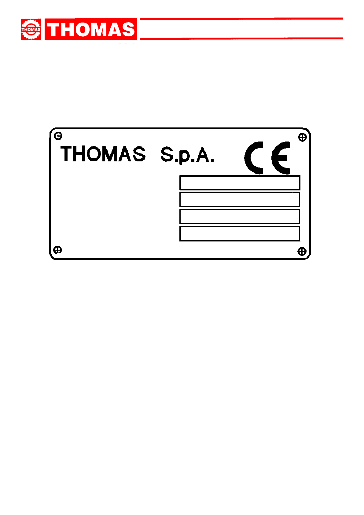
Machine certification and identification marking
MACHINE LABEL
via Pasubio, 32 36033 ISOLA VIC. - ITALIA
SAR 331 SA GDS
MODEL
TYP
SERIAL NUMBER
YEAR OF MANUFACTURE
SAR
331 SA GDS
(Space reserved for the NAME and STAMP of the DEALER and/or IMPORTER)
3
Page 4
SAR 331 SA GDS
REFERENCE TO ACCIDENT - PREVENTION REGULATIONS
1
This machine has been built to comply with the national and community accident-prevention regulations in force. Improper use
and/or tampering with the safety devices will relieve the manufacturer of all responsibility.
1.1 - Advice for the operator
- Check that the voltage indicated on the plate, normally fixed to the machine motor, is the same as the line voltage.
- Check the efficiency of your electric supply and earthing system; connect the power cable of the machine to the socket and the earth
lead yellow-green in colour) to the earthing system.
- When the saw frame is in suspend mode (up) the toothed blade must not move.
- Only the blade section used for cutting must be kept unprotected. Remove guarding by operating on the adjustable head.
- It is forbidden to work on the machine without its shields (these are all blue or grey in colour).
- Do not use any artful system or device (for ex. shim) to prevent the vice from locking the workpiece. Do not hold the workpiece with
your hand during the cutting process.
- Do not charge the workpiece from the right to the left-hand side with respect of the machine front.
- Always disconnect the machine from the power socket before blade change or carrying out any maintenance job, even in the case
of abnormal machine operation.
- Always wear suitable eye protection.
- Never put your hands or arms into the cutting area while the machine is operating.
- Do not wear loose clothing with sleeves that are too long, gloves that are too big, bracelets, chains or any other object that could get
caught in the machine during operation; tie back long hair.
- Keep the area free of equipment, tools or any other object.
- Perform only one operation at a time and never have several objects in your hands at the same time. Keep your hands as clean as
possible.
- All internal and/or internal operations, maintenance or repairs, must be performed in a well-lit area or where there is sufficient light
from extra sources so as to avoid the risk of even slight accidents.
1.2 - Location of shields against accidental contact with the tool
- Blue or grey metal shield fixed frontally with screws to the fixed blade-guiding block (Ref. A).
- Blue or grey shield fixed with screws to the adjustable blade-guiding block. Guarantees that the section of blade which exceeds the
piece to be cut is covered (Ref. B).
- Grey metal casing fixed with hooks to the frame. Protects the flywheels from blade dragging (Ref. C).
AB
C C
4
Page 5
SAR 331 SA GDS
1.3 - Electrical equipment according to European Standard "CENELEC EN 60 204-1" which assimilates,
with some integrating modifications, the publication "IEC 204-1"
- The electrical equipment ensures protection against electric shock as a result of direct or indirect contact. The active parts of this
equipment are housed in a box to which access is limited by screws that can only be removed with a special tool; the parts are fed
with alternating current at low voltage (24 V). The equipment is protected against splashes of water and dust.
- Protection of the system against short circuits is ensured by means of rapid fuses and earthing; in the event of motor overload,
protection is provided by a thermal relay.
- In the event of a power cut, the specific start-up button must be reset.
- The machine has been tested in conformity with point 20 of EN 60204.
1.4 - Emergencies according to European Standard "CENELEC EN 60 204-1"
- In the event of incorrect operation or of danger conditions, the machine may be stopped immediately by pressing the red mushroom
button.
- The casual or voluntary removal of the protection shield of the flywheels causes the stepping-in of a microswitch that automatically
stops all machine functions.
- In case blade breaks, the band tightening microswitch/pressure switch disconnects all machine.
NOTE:Resetting of machine operation after each emergency stop is achieved by reactivating the specific restart button.
1.5 - OTHER RISKS
- As the machine is running, any intervention from the operator within the “dangerous zone” or cutting area must be considered a risk
for his own safety.
RECOMMENDATIONS AND ADVICE FOR USE
2
2.1 - Recommendations and advice for using the machine
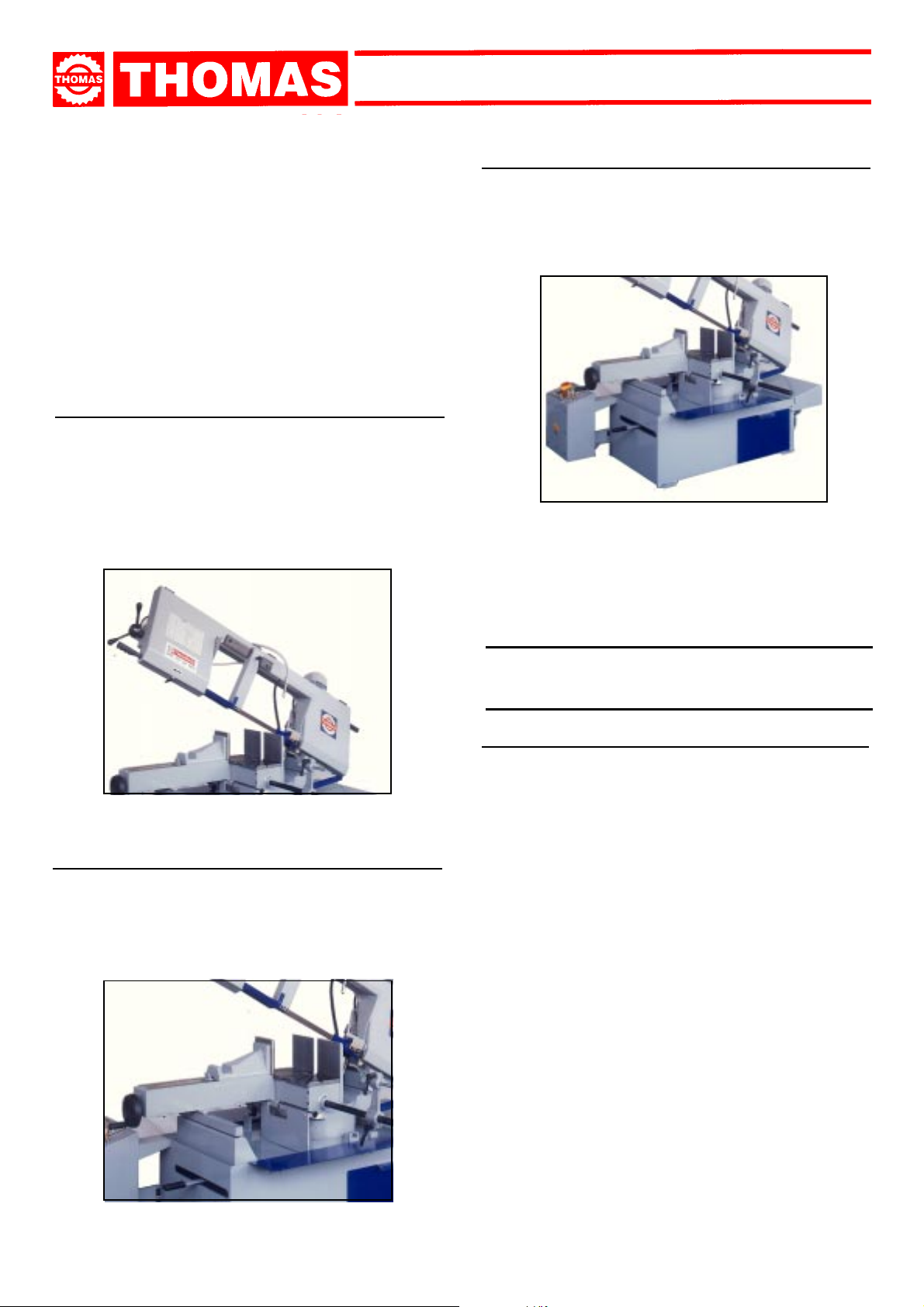
- The machine has been designed to cut metal building materials, with different shapes and profiles, used in workshops, turner’s
shops and general mechanical structural work.
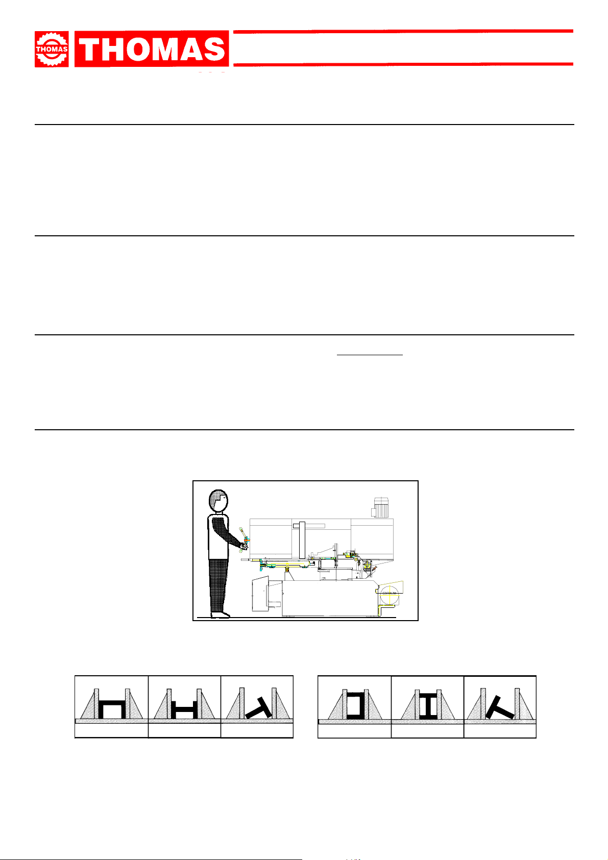
- Only one operator is needed to use the machine, that must stand as shown in the picture.
Before starting each cutting operation, ensure that the part is firmly gripped in the vice and that the end is suitably supported.
These figures show examples of suitable clamping of different section bars, bearing in mind the cutting capacities of the machine in
order to achieve a good efficiency and blade durability.
- Do not use blades of a different size from those stated in the machine specifications.
- If the blade gets stuck in the cut, release the running button immediately, switch off the machine , open the vice slowly, remo v e the part
and check that the blade or its teeth are not broken. If they are broken, change the tool.
- Check saw frame return spring to ensure proper balancing.
- Before carrying out any repairs on the machine, consult the dealer or apply to THOMAS.
5
Page 6
SAR 331 SA GDS
TECHNICAL
3
CHARACTERISTICS
3.1 - Table of cutting capacity and technical details
CAP ACITA` DI
TAGLIO
0°
45° DX
45° SX
60°
330 330x330 480x130
310 280x28 0 300x25 0
300 250x25 0 280x25 0
200 180 x180 180 x200
MACHINE DIMENSIONS
TRANSPORT
4
INSTALLATION
DISMANTLING
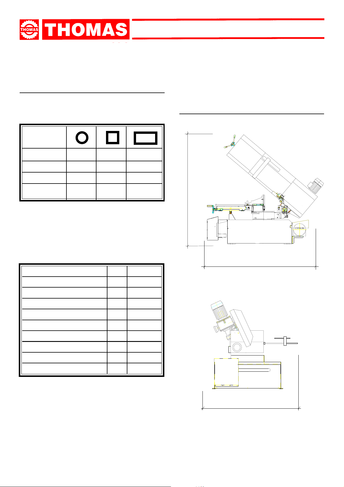
4.1 - Machine dimensions
2050
Blade motor
Hydraulic motor
Pump electric
flywheel diameter
Blade dimensions
Cutting speed
Vice opening
Saw frame inclination
Height of pieces bearing sur face
Machine weight
KW
KW
KW
mm
mm
m/1'
mm
°
mm
Kg
2150
1.5
0.37
0.18
390
3810x27x0.9
21 ÷ 116
485
25
740
720
1600
6
Page 7
SAR 331 SA GDS
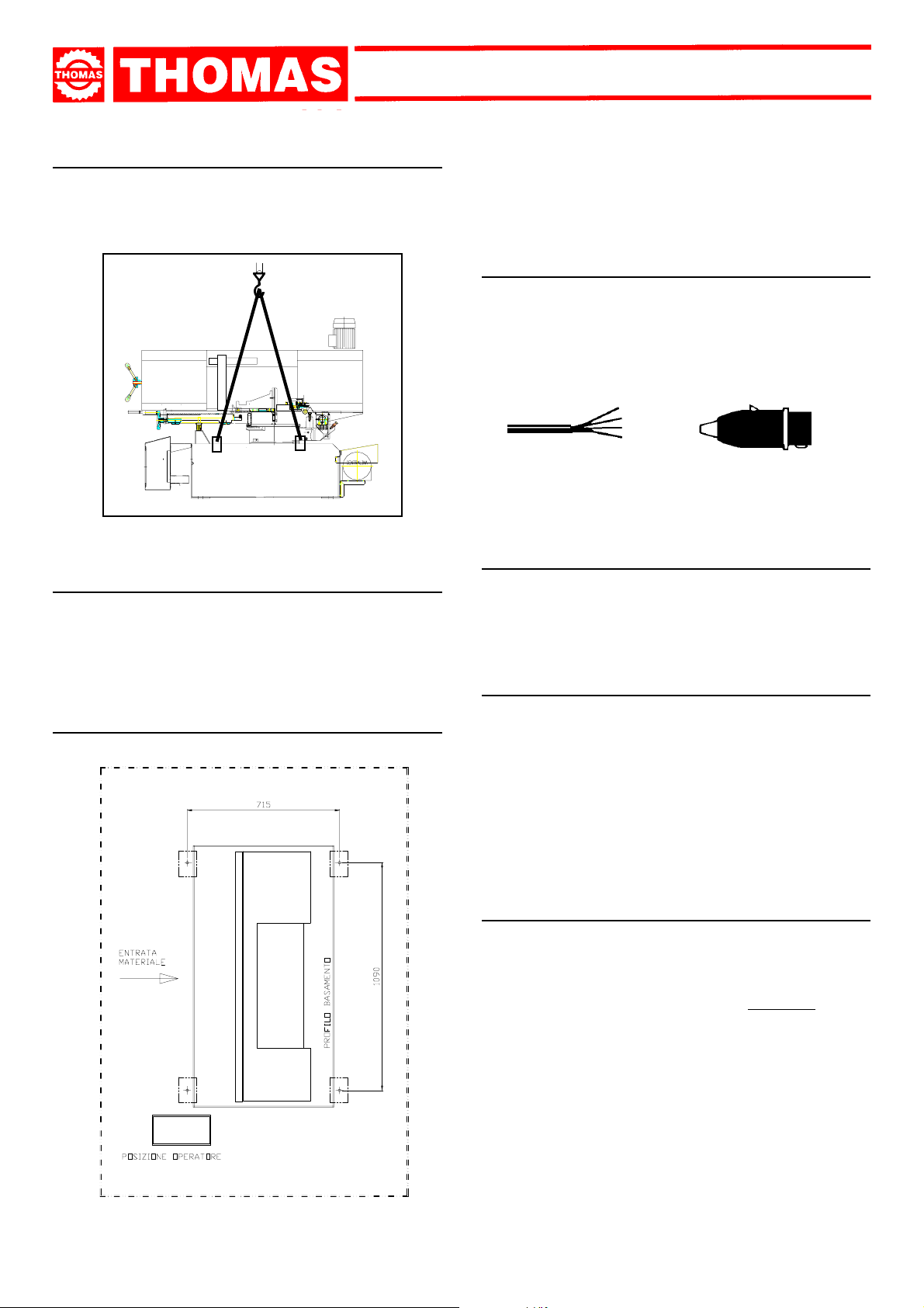
4.2 - Transport and handling of the machine
If the machine has to be shifted in its own packing, use a fork-lift
truck or sling it with straps as illustrated.
4.3 - Minimum requirements for the premises
housing the machine
- Mains voltage and frequency complying with the machine motor
characteristics.
- Environment temperature from -10 °C to +50 °C.
- Relative humidity not over 90%.
- Position the machine on a firm cement floor, maintaining, at the
rear, a minimum distance of 1000 mm from the wall; anchor it to
the ground as shown in the diagram, using screws and expansion
plugs or tie rods sunk in cement, ensuring that it is sitting level.
4.5 - Instructions for electrical connection
- The machine is not provided with an electric plug, so the customer
must fit a suitable one for his own working conditions:
1 - WIRING DIAGRAM FOR 4-WIRE SYSTEM FOR THREE-
PHASE MACHINE - SOCKET FOR A 16A PLUG
R = L1
S = L2
T = L3
PE = GND
4.6 - Instructions for assembly of the loose parts and
accessories
Fit the components supplied as indicated in the photo:
- Mount the stock stop.
- Mount the coolant liquid holder.
4.7 - Disactivating the machine
4.4 - Anchorage of standard machine
INGOMBRO OPERATIVO = mm 2100
INGOMBRO OPERATIVO = mm 2300
- If the sawing machine is to be out of use for a long period, it is
advisable to proceed as follows:
1) detach the plug from the electric supply panel
2) loosen blade
3)release the arch return spring
4) empty the coolant tank
5) carefully clean and grease the machine
6) if necessary, cover the machine.
4.8 - Dismantling
(because of deterioration and/or obsolescence)
General rules
If the machine is to be permanently demolished and/or scrapped,
divide the material to be disposed of according to type and composition, as follows:
1) Cast iron or ferrous materials, composed of
ondary raw materials, so they may be taken to an iron foundry
for re-smelting after having removed the contents (classified in
point 3);
2) electrical components, including the cable and electronic ma-terial
(magnetic cards, etc.), fall within the category of material classified as being assimilable to urban waste according to the laws of
the European community, so they may be set aside for collection
by the public waste disposal service;
3) old mineral and synthetic and/or mixed oils, emulsified oils and
greases are special refuse, so they must be collected, transported
and subsequently disposed of by the old oil disposal service.
metal alone, are sec-
7
Page 8
SAR 331 SA GDS
NOTE:since standards and legislation concerning refuse in gen-
eral is in a state of continuous evolution and therefore
subject to changes and variations, the user must keep
informed of the regulations in force at the time of disposing
of the machine tool, as these may differ from those
described above, which are to be considered as a general
guide line.
MACHINE FUNCTIONAL
5
PARTS
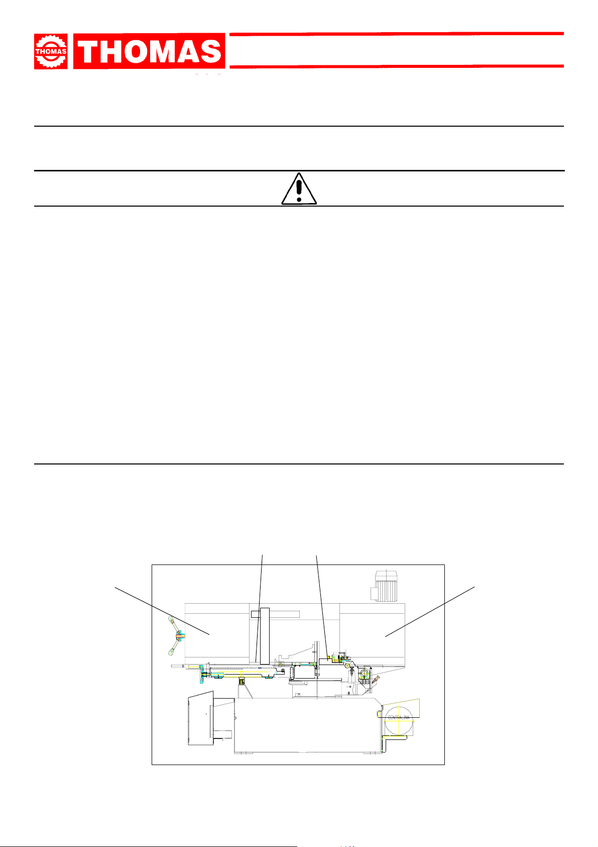
5.1 - Operating head or saw frame
- Machine part consisting of the members that transfer the motion
(gearmotor, flywheels), the tightening/guiding (blade guide arms,
blade tightening slide) and the tool lowering control.
5.3 - Bed
- Structure supporting the HEAD OR SAW FRAME, the VICE, the
SWIVEL DEVICE with relative locking system, the ELECTRICALS,
the BAR STOP and housing the coolant TANK for cut and pump.
5.2 - Vice
- Manual locking system for cutting material using the hand wheel.
This device allows for the quick shifting of the vice and the possibility
to cut inclinations to the left and right.
DESCRIPTION OF THE
6
OPERATING CYCLE
Before operating, all the main organs of the machine must
be set in optimum conditions (see the chapter on “Regulat-
ing the machine”).
6.1 - Getting started
DESCRIPTION OF THE CUTTING CYCLE:
- Manual closing of the vice;
- Activation of the cutting cycle;
- Independent lowering of the blade-carrying
frame;
- Frame raising (with selector);
- Manual opening of the vice.
PRELIMINARY OPERATIONS:
- Make sure that the machine is equipped with all the protections described in paragraph 1.2 of chapter 1.
- Position the side draining system (supplied with the machine)
on the base.
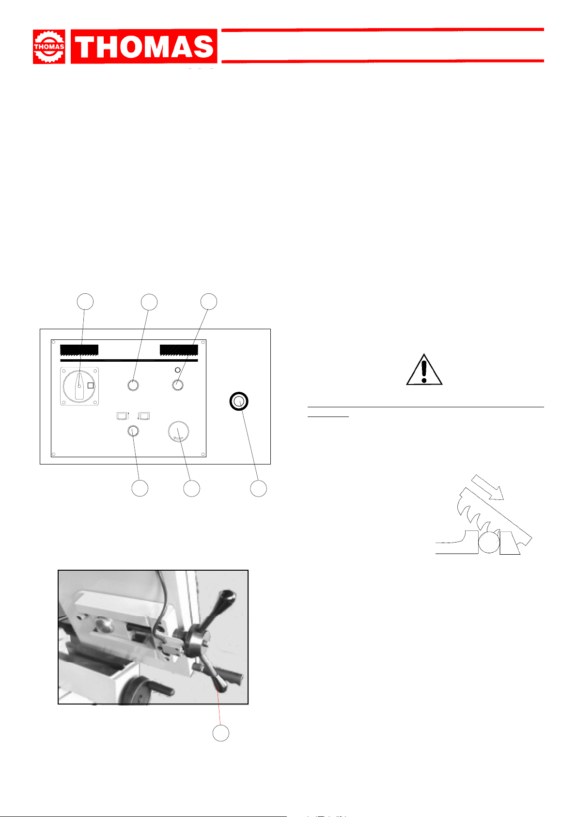
- Make sure that the machine is not in an emergency stop. If it
is, release the red mushroom pushbutton (1) on the command panel.
- Rotate the belt-tightening handwheel (8) until the relative
microswitch activates.
- Rotate the main switch (2) to position 1.
- Press the pushbutton with light (4) and make sure that the
relative indicator lights up.
- Use the selector (5) to raise the frame.
NB: invert the electric supply phases if the frame does not rise
(this should only be done during installation).
8
Page 9
SAR 331 SA GDS
- Open the vice according to the dimensions of the material to
be cut.
- Place the material to be cut in the vice and lock using the
handwheel. Make sure that the relative pawl is interlocked
with the rack.
- Free the hand le v er and move the mobile belt-guiding arm as
close as possible to the piece to be cut (up to approx. 10mm)
then lock the hand lever.
- Make sure that the cutting angle corresponds to the desired
inclination and that the angling device is locked using the
relative lever (see paragraph 7.4 of chapter 7).
- Make sure that the hydraulic regulator (6) is fully closed, then
rotate counter clockwise to set the most suitable lowering
speed for the characteristics of the material to be cut. It is
advisable to always start from a cautionary speed and increase subsequently if necessary.
2
3
4
SAR
START
1
- Always make sure that the vice is positioned at the extreme
right or left of the countervice to avoid accidental contact with
the frame.
- Before starting the cutting cycle it is advisable to move the
blade to approx. 10mm from the piece to be cut, using the
selector (5) if necessary.
- Press the pushbutton (3) to start the cutting cycle. Make sure
that the belt turns in the correct direction and that a sufficient
quantity of cooling liquid exits.
NB: The weight of the blade-carrying frame causes it to lower
automatically without needing the intervention of Operator. If
greater cutting pressure is necessary, modify the tightness of
the frame return spring (see paragraph 7.8 of chapter 7).
- Use the variator group handwheel to set the most suitable
cutting speed for the material to be cut. This operation must
always be carried out while the motor is running).
To set the necessary speed, refer to the plate applied onboard the machine or shown below.
- Press the emergency pushbutton if incorrect manoeuvres are
made, or if the cutting cycle is to be stopped.
- When finished cutting, the frame stops in the lower position.
Use the selector (5) to raise the frame.
NB: Do not use the sawing machine at full material discharge speed during the first 50 working hours.
Keep a safe distance from the cutting area during machine
operation.
5
1
6
CUTTING DIRECTION
The sawing machine is now ready to start working. Please
remember that the CUTTING SPEED and the TYPE of blade
when combined with suitable frame lowering have a determinate effect on the cutting quality and machine return (for more
information on this topic, refer to the "Material classification
and blade choice" chapter)
- When starting to cut with a new blade, it is necessary to
exert a light pressure on the piece during the first two or
three cuts, in order to use a cutting time that is almost
double the normal one (refer to the
graph in the "Material classification and blade choice" chapter further on in this manual).
- Use the red emergency pushbutton (1) when dangerous conditions or faults in general arise. Doing so immediately interrupts machine operation.
Blade breaking-in
para-
8
9
Page 10
REGULATING
7
THE MACHINE
7.1 - Blade tension assembly
SAR 331 SA GDS
4
The ideal blade tension is obtained by turning the belt-tightening handwheel until the relative microswitch activates (B).
The position of the microswitch is established by an instrument that measures the blade stretch. This regulation m ust not
be modified.
NB: it is advisable to loosen the blade tension when the saw is not
being used.
It is advisable to always use blades having the dimensions declared
in this manual.
B
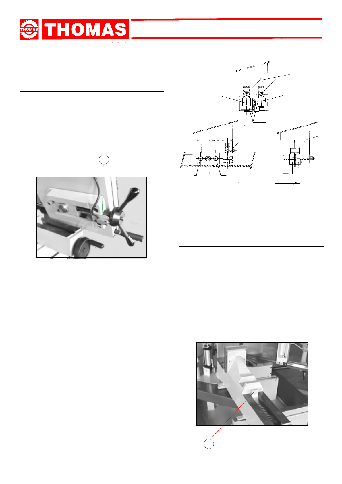
7.2 - Blade-guiding arms and plates
The blade is guided by plates that are regulated during the
testing phase according to the thickness of the blade. The minimum clearance indicated in the figures should be maintained.
When the blade is to be replaced, make sure to always fit belts
with a 0.9 mm thickness because the blade-guiding plates have
been regulated for this thickness. If using toothed belts with
different thicknesses a new regulation must be carried out as
follows:
- Loosen the screw (1) and unscrew the grub screws (2), widening the space between the plates.
- Loosen the nuts (3) and the grub screws (4) and rotate the
pins (5 - 6) to widen the space between the bearings (7).
- Insert the new blade, then place the plate (8) against it. Tighten
the grub screws (2), leaving a 0.04 mm clearance to ensure
that the toothed belt slides well. After this, tighten the relative
nuts and the screw (1).
- Rotate the pins (5 - 6) until the bearings lean against the
blade, as indicated in the figure. Lock the grub screws (4) and
the nuts (3).
6
7
3
22
1
5
8
0,04
7.3 - Vice
- The vice can be made to move rapidly towards the piece to be
cut by keeping the hand lever (C) raised and moving the vice
manually. Before using the handwheel to lock the material to
be cut, make sure that the hand lever is interlocked with the
rack.
- The vice group can be positioned to the right or left of the
blade. If positioning is not fully completed, the sawing machine can be permanently damaged by the lowering movement of the frame.
- Always keep the vice guide and relative thread clean and
oiled.
10
C
Page 11

SAR 331 SA GDS
7.4 - Regulating the cutting angle
- Raise the frame to a position that avoids contact with the piece
supporting surface and the material to be cut.
- Push the lever (D) to the left in order to free the rotation device.
- Rotate the frame group to the necessary angle, referring to
the graduated sector.
- Use the mechanical stops on the machine base to make positioning at 45° / 60° easier. If necessary , rotate the mechanical
stops to permit movement of the rotating arm.
- When finished, push the lever (D) to the right in order to lock
the rotation device.
7.7 - Regulating the cutting speed
The cutting speed should only be regulated while the belt rotation motor is running.
Use the relative handwheel and refer to the relative plate in
order to set the necessary speed.
D
7.5 - Blade-cleaning brush
This is an excellent accessory for cleaning the blade during the
cutting cycle. Periodically check brush integrity and if necessary regulate further to guarantee perfect blade cleaning.
7.6 - Regulating the cutting height
With this accessory it is possible to raise the frame and/or
move it closer to the piece to be cut.
- Use the selector (E) to move the frame to the necessary posi-
tion.
- It is advisable to position the blade at a distance of 10mm from
the material to be cut.
- To permit the frame lowering movement, open the hydraulic
regulator on the command panel.
SAR
2
1
START
POS. N° m/min .
021
123,5
226
328,5
431
533,5
636
738,5
841
943,5
10 46
11 48,5
12 51
13 53,5
14 56
15 58,5
16 61
17 62,5
18 64,5
POS. N° m/mi n .
19 66
20 68
21 71, 5
22 74, 5
23 78
24 81, 5
25 85
26 87, 5
27 90
28 93
29 96
30 99
31 102,5
32 1 05,5
33 1 08,5
34 111
35 1 13,5
36 116
E
11
Page 12

SAR 331 SA GDS
7.8 - Regulating the frame raising spring
- It is possible to modify the tension of the frame return spring in
order to obtain increased cutting pressure while lowering to
cut.
- Loosen the nut (F) to remove tension from the spring until the
desired tension has been reached.
- NB: the spring tension should not be loosened in an exaggerated manner. Doing so can influence the balance of the b ladecarrying frame.
F
7.10 – Replacement of the return spring arch
- During the entire operation, it will be necessary to keep the
arch lifted and secured.
- First loosen the tension spring and unhook it from the
supporting spring immediately behind.
PROBABLE REPLACEMENT OF OTHER PARTS –
REDUCTION GEAR OR SPEED CONTROL, MOTOR PUMP
AND ELECTRICAL COMPONENTS – TO BE EXECUTED BY
SPECIALISED AND COMPETENT PERSONNEL.
ROUTINE
AND SPECIAL
8
MAINTENANCE
BEFORE PERFORMING THE FOLLOWING OPERA TIONS, THE
ELECTRIC POWER SUPPLY AND THE PO WER CABLE MUST
BE COMPLETELY DISCONNECTED.
7.9 – Replacing the blade
- Raise the frame to the high position.
- Use the handwheel to loosen the blade, remove the mobile
blade-guiding shield and the belt-cleaning brush shield.
- Open first the rear then the front flywheel casing and extract
the old blade from the flywheels and the blade-guiding blocks.
- Position the new blade, placing it firstly among the plates and then
on the flywheel seats. Make sure that the teeth are positioned in the
correct direction for cutting (see drawing below).
- Tighten the blade, making sure it adapts perfectly to the flywheel seats.
- Reposition the mobile blade-guiding shield, the belt-cleaning
brush shield and close the flywheel casings. Make sure that
the safety microswitch activates, otherwise the machine will
not start when powered again.
WARNING: alwa ys use blades having the dimensions specified in this manual and for which the blade guide heads
have been set: otherwise, see chapter on "Description of
the operating cycle" in the Starting-up section.
CUTTING DIRECTION
THE MAINTENANCE JOBS ARE LISTED BELOW, DIVIDED INTO
DAILY, WEEKLY, MONTHLY AND SIX-MONTHLY INTERVALS. IF
THE FOLLOWING OPERATIONS ARE NEGLECTED, THE RESULT
WILL BE PREMATURE WEAR OF THE MACHINE AND POOR
PERFORMANCE.
8.1 - Daily maintenance
- General cleaning of the machine to remove accumulated shavings.
- Clean the lubricating coolant drain hole to avoid excess fluid.
- Top up the level of lubricating coolant.
- Check blade for wear.
- Rise of saw frame to top position and partial slackening of the
blade to avoid useless yield stress.
- Check functionality of the shields and emergency stops.
8.2 - Weekly maintenance
- More accurate general cleaning of the machine to remove shavings, especially from the lubricant fluid tank.
- Removal of pump from its housing, cleaning of the suction filter
and suction zone.
- Clean the filter of the pump suction head and the suction
area.
- Cleaning with compressed air of blade guide arms (guide
bearings, pads and drain hole of the lubricating cooling).
- Cleaning flywheel housings and blade sliding surfaces on
flywheels.
- Check condition of the blade cleaning brushes.
- Greasing of motor flywheel bearings.
12
Page 13

8.3 - Monthly maintenance
- Check the tightening of the motor flywheel screws.
- Check that the blade guide bearings on arms are perfect running
condition.
- Check the tightening of the screws of the gearmotor, pump and
accident protection guarding.
8.4 - Six-monthly maintenance
REDUCER:
- It is advisable to carry out the first oil change after around 300
working hours. Wash the internal parts accurately. Use synthetic lubricant of the SHELL TIVELA OIL SC 320 type or similar.
- The next oil change should be carried out after approx. 2000
working hours.
VARIATOR:
- Replace the variator oil after approx. 2000 working hours. Use
SHELL DONAX TA oil or similar.
- NB: never mix synthetic oil with mineral oil.
SAR 331 SA GDS
- Completely replace the hydraulic switchboard oil at least once
every year. Use SHELL HYDRAULIC OIL 32 or similar.
- Carry out a continuity test on the unipotential protection circuit.
8.5 - Oils for lubricating coolant
Considering the vast range of products on the market, the user
can choose the one most suited to his own requirements, using
as a reference the SHELL LUTEM OIL ECO type.
THE MINIMUM PERCENTAGE OF OIL DILUTED IN WATER IS
8 - 10 %.
8.6 - Oil disposal
The disposal of these products is controlled by strict regulations. Please see the Chapter on “Machine dimensions - T rans-
port - Installation” in the section on
Dismantling
.
8.7 - Special maintenance
Special maintenance operations must be carried out by skilled
personnel.
However, we advise contacting THOMAS or their dealer and/or
importer. Adjusting the protective and safety equipment and
devices, the reducer, the motor, the motor pump and electric
components are classed as special maintenance operations.
13
Page 14

SAR 331 SA GDS
MATERIAL
CLASSIFICATION AND
9
CHOICE OF TOOL
Since the aim is to obtain excellent cutting quality, the various
parameters such as hardness of the material, shape and thick-
ness, transverse cutting section of the part to be cut, selec-
tion of the type of cutting blade, cutting speed and control of
saw frame lowering.These specifications must therefore be har-
moniously combined in a single operating condition according to
practical considerations and common sense, so as to achieve
an optimum condition that does not require countless operations to prepare the machine when there are many variations in
the job to be performed.The various problems that crop up from
time to time will be solved more easily if the operator has a good
knoledge of these specifications.
WE THEREFORE RECOMMEND YOU TO ALWAYS USE
GENUINE SP ARE BLADES THAT GUARANTEE SUPERIOR
QUALITY AND PERFORMANCE.
9.1 - Definition of materials
The table at the foot of the page lists the characteristics of the materials to be cut, so as to choose the right tool to use.
9.2 - Selecting blade
be cut, according to these criteria:
- parts with a thin and/or variable section such as profiles, pipes
and plate, need close toothing, so that the number of teeth used
simultaneously in cutting is from 3 to 6;
- parts with large transverse sections and solid sections need widely
spaced toothing to allow for the greater volume of the shavings
and better tooth penetration;
- parts made of soft material or plastic (light alloys, mild bronze,
teflon, wood, etc.) also require widely spaced toothing;
- pieces cut in bundles require combo tooth design.
9.3 - Teeth pitch
As already stated, this depends on the following factors:
- hardness of the material
- dimensions of the section
- thickness of the wall.
BLADE TEETH SELECTION TABLE
THICKNESS MM
TILL 1.5 14 10/14
FROM 1 TO 2 8 8/12
FROM 2 TO 3 6 6/10
FROM 3 TO 5 6 5/8
FROM 4 TO 6 6 4/6
MORE THAN 6 4 4/6
Z CONTINUOUS
TOOTH DESIGN
Z COMBO
TOOTH DESIGN
First of all the pitch of the teeth must be chosen, in the other words,
the number of teeth per inch (25,4 mm) suitable for thematerial to
TYPES OF STEEL CHARACTERISTICS
USE
Construction
steels
Carbon
steels
Spring
steels
Alloyed steels for
hardening and
tempering and for
nitriding
Alloyed
casehardening
steels
Alloyed for
bearings
Tool steel
Stainless
steels
Copper alloys
Special brass
Bronze
Cast iron
I
UNI
Fe360
Fe430
Fe510
C20
C40
C50
C60
50CrV4
60SiCr8
35CrMo4
39NiCrMo4
41CrAlMo7
18NiCrMo7
20NiCrMo2
100Cr6 100Cr6 100C6 534 A 99 52100 207 95 690÷980
52NiCrMoKU
C100KU
X210Cr13KU
58SiMo8KU
X12Cr13
X5CrNi1810
X8CrNi1910
X8CrNiMo1713
Aluminium copper alloy G-CuAl11Fe4Ni4 UNI 5275
Special manganese/silicon brass G-CuZn36Si1Pb1 UNI5038
Manganese bronze SAE43 - SAE430
Phosphor bronze G-CuSn12 UNI 7013/2a
Gray pig iron G25
Spheroidal graphite cast iron GS600
Malleable cast iron W40-05
56NiCrMoV7C100K
D
DIN
St37
St44
St52
CK20
CK40
CK50
CK60
50CrV4
60SiCr7
34CrMo4
36CrNiMo4
41CrAlMo7
----
21NiCrMo2
C100W1
X210Cr12
----
4001
4301
----
4401
F
AF NOR
E24
E28
E36
XC20
XC42H1
----
XC55
50CV4
----
35CD4
39NCD4
40CADG12
20NCD7
20NCD2
----
----
Z200C12
Y60SC7
----
Z5CN18.09
----
Z6CDN17.12
GB
SB
---43
50
060 A 20
060 A 40
----
060 A 62
735 A 50
----
708 A 37
----
905 M 39
En 325
805 H 20
----
BS 1
BD2-BD3
----
----
304 C 12
----
316 S 16
USA
AISI-SAE
----
----
---1020
1040
1050
1060
6150
9262
4135
9840
---4320
4315
----
S-1
D6-D3
S5
410
304
----
316
S = THICKNESS
Hardness
BRINELL
HB
116
148
180
198
198
202
202
207
224
220
228
232
232
224
244
212
252
244
202
202
202
202
220
140
120
100
212
232
222
Hardness
ROCKWELL
HRB
67
80
88
93
93
94
94
95
98
98
99
100
100
98
102
96
103
102
94
94
94
94
98
77
69
56,5
96
100
98
R=N/mm²
360÷480
430÷560
510÷660
540÷690
700÷840
760÷900
830÷980
1140÷1330
1220÷1400
780÷930
880÷1080
930÷1130
760÷1030
690÷980
800÷1030
710÷980
820÷1060
800÷1030
670÷885
590÷685
540÷685
490÷685
620÷685
375÷440
320÷410
265÷314
245
600
420
14
Page 15

SAR 331 SA GDS
SOLID Ø OR L MM
TILL 30 8
FROM 30 TO 60 6
FROM 40 TO 80 4 4/6
MORE THAN 90 3 3/4
Z CONTINUOUS
TOOTH DESIGN
Ø = DIAMETER L = WIDTH
Z COMBO
TOOTH DESIGN
5/8
4/6
9.4 - Cutting and advance speed
The cutting speed (m/min) and the advance speed (cm2/min = area
travelled by the disk teeth when removing shavings) are limited by
the development of heat close to the tips of the teeth.
- The cutting speed is subordinate to the resistance of the material
(R = N/mm
widest section.
- Too high an advance speed (= lowering of the saw frame) tends to
cause the disk to deviate from the ideal cutting path, producing
non rectilinear cuts on both the vertical and the horizontal plane.
The best combination of these two parameters can be seen directly
examining the chips.
Long spiral-shaped chips indicate ideal cutting.
2
), to its hardness (HRC) and to the dimensions of the
9.7 - Blade type
They differ essentially in their constructive characteristics, such as:
- shape and cutting angle of tooth
- pitch
- set
Shape and angle of tooth
REGULAR TOOTH: 0° rake and constant pitch.
Most common form for transversal or inclined cutting of solid small
and average cross-sections or pipes, in laminated mild steel and
grey iron or general metal.
POSITIVE RAKE TOOTH: 9° - 10° positive rake and constant pitch.
positive
Particular use for crosswise or inclined cuts in solid sections or large
pipes, but above all harder materials (highly alloyed and stainless
steels, special bronze and forge pig).
Very fine or pulverized chips indicate lack of
feed and/or cutting pressure.
Thick and/or blue chips indicate overload of
the blade.
9.5 - Blade running-in
When cutting for the first time, it is good practice to run in the
tool making a series of cuts at a low advance speed
(= 30-35 cm
to the cutting capacity and solid section of normal steel with R =
410-510 N/mm
2
/min on material of average dimensions with respect
2
), generously spraying the cutting area with lu-
bricating coolant.
9.6 - Blade structure
Bi-metal blades are the most commonly used. They consist in a silicon-steel blade backing with electron beam or laser welded high speed
steel (HHS) cutting edge. The type of stocks are classified in M2,
M42, M51 and differ from each other because of their major hardness due to the increasing percentage of Cobalt (Co) and molybdenum (Mo) contained in the metal alloy.
COMBO TOOTH: pitch varies between teeth and consequently varying teeth size and varying gullet depths. Pitch varies between teeth
which ensures a smoother, quieter cut and longer blade life owing to
the lack of vibration.
Another advantage offered in the use of this type of blade in the fact
that with an only blade it is possible to cut a wide range of different
distance between teeth
materials in size and type.
COMBO TOOTH: 9° - 10° positive rake.
positive
This type of blade is the most suitable for the cutting of section bars
and large and thick pipes as well as for the cutting of solid bars at
maximum machine capacity. Available pitches: 3-4/4-6.
15
Page 16

SAR 331 SA GDS
Set
Saw teeth bent out of the plane of the saw body, resulting in a wide
cut in the workpiece.
REGULAR OR RAKER SET: Cutting teeth right and left, alternated
by a straight tooth.
Of general use for materials with dimensions superior to 5 mm. Used
for the cutting of steel, castings and hard nonferrous materials.
WAVY SET: Set in smooth waves.
This set is associated with very fine teeth and it is mainly used for
9.7.1 - RECOMMENDED CUTTING PARAMETERS
the cutting of pipes and thin section bars (from 1 to 3 mm).
ALTERNATE SET (IN GROUPS): Groups of cutting teeth right and
left, alternated by a straight tooth.
This set is associated with very fine teeth and it is used for extremely
thin materials (less than 1 mm).
ALTERNATE SET (INDIVIDUAL TEETH): Cutting teeth right and left.
This set is used for the cutting of nonferrous soft materials, plastics
and wood.
STEEL C UTTING SPEED LUBRICATION
CONSTRUCTION 60/80 EMULSIFIABLE OIL
CEMENTATION 40/50 EMULSIFIABLE OIL
CARBON STEEL 40/60 EMULSIFIABLE OIL
HARDENING A ND TE MPE RING 40/50 EMULSIFIABLE OIL
BEARINGS 40/60 EMULSIFIABLE OIL
SPRINGS 40/60 EMULSIFIABLE OIL
FOR TOOLS 30/40 EMULSIFIABLE OIL
FOR VALVES 35/50 EMULSIFIABLE OIL
STAINLESS STEEL 30/40 EMULSIFIABLE OIL
SPHEROIDAL GRAPHITE 20/40 EMULSIFIABLE OIL
CAST IRON 40/60 EMULSIFIABLE OIL
16
ALUMINIUM 80/600 KEROSENE
BRONZE 70/120 EMULSIFIABLE OIL
HARD BRONZE 30/60 EMULSIFIABLE OIL
BRASS 70/350 EMULSIFIABLE OIL
COPPER 50/720 EMULSIFIABLE OIL
Page 17

SAR 331 SA GDS
10
MACHINE COMPONENTS
10.1 - List of spare parts
REFERENCE NUMBER DENOMINATION
1 Bedframe
2 Electric box
3 Electric box cover
4 Revolving arm lock lever
5 Arm lock bush
6 Machine hoisting hook
7 Crucible
8 Hydraulic unit cover
9 Cover
10 Refrigeranting liquid tank
11 Electropump
12 Bar stop body
13 Bar stop push rod
14 Bar stop rod
15 Revolving arm pin
16 Vice support
17 Revolving arm
18 Bearing 32008 X
19 Bushing
20 Screw
21 Hinge pin protection
22 Bearing 32008 X
23 Spacer
24 Hinge pin
25 Ring nut Guk M 40 x 1,5
26 Countervice r.h. jaw
27 Countervice l.h. jaw
28 Interchangeable plate
29 Countervice
30 Countervice anterior guard
31 Hinge pin support
32
33 Vice support
34 Rack
35 Rack support
36 Vice
37 Vice screw
38 Vice handwheel
39 Pin
40 Pawl
41 Vice jaw
42
43 Ring NILOS 32008 XAV
44 spring support
45 Spring
46
REFERENCE NUMBER DENOMINATION
60 Saw frame
61 Electric motor
62 Speed variator
63 Speed variator handwheel
64 Ring nut M 35 x 1,5
65 Speed reducer
66 Spacer
67 Cylinder sawframe superior
attacchment
68 Spacer flange
69
70 Microswith
71 Cylinder sawframe inferior
attacchment
72 Pin
73 Pin
74 Hydraulic cylinder
( SA GDS version )
75 Adjustable screw
76 Transmission flywheel pin
77 Ring nut Guk M 30 x 1,5
78 Blade tightening slide
79 Microswitch
80 Microswitch support plate
81 Handgripp
82 Blade tightening handwheel
pin
83 Blade tightening
handwheel
84 Blade tightening pin
85 Spring
86 Bracket
87 Ring NILOS 32006 XAV
88 Bearing 32006 X
89 Transmission flywheel
90 Ring nut Guk M 30 x 1,5
91 Bearing 6308 2RS
92 Ring NILOS 6308 AV
93 Bearing guard
94 Motor flywheel shaft
95 Motor flywheel
96 Cone clamping EURONIC
CN 54/S
97 Blade guide protection
98 Microswitch
99 R.h. flywheel protection
10 0 L.h. flywheel protection
10 1 Blade guide arm guide
10 2 Blade guide arm
103
104 Hand lever
17
Page 18

REFERENCE NUMBER DENOMINATION
105
106 Additional protection
10 7 Fixed blade guide block
108 Blade cleaning brush
10 9 Brush support
11 0 Bearing 626
111 Bush
112
11 3 Short eccentric pin
11 4 Long eccentric pin
11 5 bearing 608 2RS
116 ring seeger
11 7 Upper blade guide pad
11 8 Side blade guide pad
119
120 Crucible
121 Coupling
122 Coupling
123 Cooling liquid cock
124 Flexible tube
125 Cooling distributor
126 Coupling
127
128
129
130 Bracke cylinder
( GDS version )
SAR 331 SA GDS
18
Page 19

SAR 331 SA GDS
7
9
8
7
21
19
43
44
45
47
46
22
43
23
24
25
20
18
31
17
26
27
28
12
13
14
15
29
11
16
30
34
10
6
6
5
4
1
2
35
33
3
37
41
36
38
39
40
19
Page 20

20
121
124
ZOOM - 3
122 126
123
126
123
125
61
130
74
121
73
76
77
75
78
79
80
81
82
83
86
84
85
71
87
88
113
114
115
116
63
64
65
67
72
70
89
88
117
118
62
68
66
101
102
90
87
97
100
104
106
60
98
91
93
94
107
120
92
95
96
119
117
118
111
110 109
99
ZOOM 2
ZOOM 4
108
114
113
115
116
SAR 331 SA GDS
ZOOM 1
Page 21

407
SAR 331 SA GDS
KEY:
401 Main switch
402 Frame movement selector
403 Emergency pushbutton
404
405 Frame lowering regulator
406 Line pushbutton
407 Cycle start pushbutton
408 Indicator light
KEY:
411 Fuse holders (FU 1)
412 Fuse holders (FU 2)
413 Fuse holders (FU 3)
414 Relay
415 Hyd. switchboard motor teleswitch
416 Belt motor circuit breaker
417 Belt motor teleswitch
418 Transformer
401
SAR
START
1
408
406
405
402
403
418
417
KEY:
421 Hyd. switchboard motor
422 Solenoid valve
423 Hyd. switchboard casing
424 Regulator
411
421
412 413
414
415
423422
416
424
21
Page 22

SAR 331 SA GDS
11
11.1 - Three-phase electric diagram
ELECTRIC DIA GRAM
THOMAS
THOMAS
22
QS1 Main switch
FU1 Fuse cartridge
KM1 Central motor control switch id.
KM2 Motor belt control switch
FR2 Thermal motor belt
M1 Motor gear case id.
M2 Belt motor
M3 Motor pump
FU2 Fuse cartridge
TC1 T r ansformer
Page 23

SAR 331 SA GDS
THOMAS
THOMAS
FU3 Fuse cartridge
SB1 Emergency switch
SB2 On-line switch
KA Relay
HL Pilot light
SQ1 Dip-switch
SA1 Arch selector
EF RC coil
SQ2 Dip-switch
SQ3 Dip-switch
23
Page 24

SAR 331 SA GDS
01 Sawframe downfeed regulator
02 Sawframe lifting speed regulator
03 Valve
04 Electric valve
05 Valve
06 Valve
24
Page 25

SAR 331 SA GDS
12
This chapter lists the probable faults and malfunctions that could occur while the machine is being used and suggests possible remedies for
solving them.
The first paragraph provides diagnosis for TOOLS and CUTS, the second for ELECTRICAL COMPONENTS.
TROUBLESHOOTING
12.1 - Blade and cut diagnosis
FAULT PROBABLE CAUSE REMEDY
TOOTH BREAKAGE
Too fast advance
Wrong cutting speed
Wrong tooth pitch
Chips sticking onto teeth and in the gullets or material that gums
Defects on the material or material too
hard
Ineffective gripping of the part in the vice
Decrease advance, exerting less cutting
pressure. Adjust the braking device if
mounted on the machine.
Change speed and/or type of blade.
See chapter on “Material classification and
blade selection”, in the section
tion table according to cutting and feed
speed.
Choose a suitable blade. See Chapter “Ma-
terial classification and blade selection”.
Check for clogging of cooling liquid drain
holes on the blade-guide pads and that flow
is plentiful in order to facilitate the removal
of chips from the blade.
Material surfaces can be oxidised or covered
with impurities making them, at the beginning of the cut, harder that the blade itself,
or have hardened areas or inclusions inside
the section due to productive agents used
such as casting sand, welding wastes, etc.
Avoid cutting these materials or in any case
perform cutting with extreme care, cleaning and removing such impurities as quickly
as possible.
Check the gripping of the part.
Blade selec-
The blade gets stuck in the material
Starting cut on sharp or irregular section bars
Poor quality blade
Previously broken tooth left in the cut
Cutting resumed on a groove made pre-
viously
Vibrations
Wrong tooth pitch or shape
Insufficient lubricating refrigerant or
wrong emulsion
Teeth positioned in the direction opposite the cutting direction
Reduce feed and exert less cutting pressure.
Pay more attention when y ou start cutting.
Use a superior quality blade.
Accurately remove all the parts left in.
Make the cut elsewhere, turning the part.
Check gripping of the part.
Replace blade with a more suitable one.
See “Material classification and blade
selection” in the
Adjust blade guide pads.
Check level of liquid in the tank. Increase the
flow of lubricating refrigerant, checking that
the hole and the liquid outlet pipe are not
blocked.
Check the emulsion percentage.
Turn teeth in correct direction.
Blade Types
section.
25
Page 26

SAR 331 SA GDS
FAULT PROBABLE CAUSE REMEDY
PREMATURE BLADE WEAR
Faulty running-in of blade
Teeth positioned in the direction opposite the cutting direction
Poor quality blade
Too fast advance
Wrong cutting speed
Defects on the material or material too
hard
Insufficient lubricating refrigerant or
wrong emulsion
See “Material classification and blade se-
lection” in the
Turn teeth in correct direction.
Use a superior quality blade.
Decrease advance, exerting less cutting
pressure. Adjust the braking device if
mounted on the machine.
Change speed and/or type of blade.
See chapter on “Material classification and
blade selection”, in the section
Blade running-in
section.
Blade selection table according to cutting and feed
speed.
Material surfaces can be oxidised or covered
with impurities making them, at the beginning of the cut, harder that the blade itself,
or have hardened areas or inclusions inside
the section due to productive agents used
such as casting sand, welding wastes, etc.
Avoid cutting these materials or in any case
perform cutting with extreme care, cleaning and removing such impurities as quickly
as possible.
Check level of liquid in the tank. Increase the
flow of lubricating refrigerant, checking that
the hole and the liquid outlet pipe are not
blocked.
Check the emulsion percentage.
BLADE BREAKAGE
Faulty welding of blade
Too fast advance
Wrong cutting speed
Wrong tooth pitch
Ineffective gripping of the part in the vice
Blade touching material at beginning of
cut
The welding of the blade is of utmost importance. The meeting surfaces must perfectly
match and once they are welded they must
have no inclusions or bubbles; the welded
part must be perfectly smooth and even.
They must be evenly thick and have no bulges
that can cause dents or instant breakage
when sliding between the blade guide pads.
Decrease advance, exerting less cutting
pressure. Adjust the braking device if
mounted on the machine.
Change speed and/or type of blade.
See chapter on “Material classification and
blade selection”, in the section
Blade selection table according to cutting and feed
speed.
Choose a suitable blade. See Chapter “Ma-
terial classification and blade selection”.
Check the gripping of the part.
At the beginning of the cutting process,
never lower the saw frame before starting
the blade motor.
26
Page 27

SAR 331 SA GDS
FAULT PROBABLE CAUSE REMEDY
STREAKED OR ETCHED BANDS
Blade guide pads not regulated or dirty
because of lack of maintenance
Blade guide block too far from material
to be cut
Improper position of blade on flywheels
Insufficient lubricating refrigerant or
wrong emulsion
Damaged or chipped blade guide
pad
Tight or slackened blade guide bearing
Check distance between blocks (see “Ma-
chine adjustments” in the
Blocks
section): extremely accurate guiding
may cause cracks and breakage of the tooth.
Clean carefully.
Approach head as near as possible to material to be cut so that only the blade section
employed in the cut is free, this will prevent
deflections that would excessively stress the
blade.
The back of blade rubs against the support
due to deformed or poorly welded bands (tapered), causing cracks and swelling of the
back contour.
Check level of liquid in the tank. Increase the
flow of lubricating refrigerant, checking that
the hole and the liquid outlet pipe are not
blocked. Check the emulsion percentage.
Replace it.
Adjust it (see Chapter “Machine adjust-
ments” in
Blade guide
Blade Guide
section).
CUTS OFF THE STRAIGHT
Blade not parallel as to the counter-vice
Blade not perpendicular due to the excessive play between the guide pads
and maladjustment of the blocks
T oo f ast advance
Blade guide block too far from material
to be cut
Worn out blade
Wrong tooth pitch
Check fastenings of the blade guide blocks
as to the counter-vice so that they are not
too loose and adjust blocks vertically; bring
into line the position of the degrees and if
necessary adjust the stop screws of the
degree cuts.
Check and vertically re-adjust the blade guide
blocks; reset proper side guide play (see
Chapter “Machine adjustments” in
guide
section).
Decrease advance, exerting less cutting
pressure. Adjust the braking device if
mounted on the machine.
Approach it as near as possible to material
to be cut so that only the blade section employed in the cut is free, this will prevent deflections that would excessively stress the
blade.
Replace it.
Blade with major density of teeth is being
used, try using one with less teeth (see Chapter “Material classification and blade se-
lection” in the
Blade Types
section).
Blade
27
Page 28

SAR 331 SA GDS
FAULT PROBABLE CAUSE REMEDY
FAULTY CUT
STREAKED CUTTING SURFACE
Broken teeth
Insufficient lubricating refrigerant or
wrong emulsion
Worn out flywheels
Flywheel housing full of chips
Too fast advance
Poor quality blade
Worn out blade or with chipped and/or
broken teeth
Wrong tooth pitch
Blade guide block too far from material
to be cut
Irregular work of the blade due to the lack of
teeth can cause deflection in the cut; check
blade and if necessary replace it.
Check level of liquid in the tank. Increase the
flow of lubricating refrigerant, checking that
the hole and the liquid outlet pipe are not
blocked.
Check the emulsion percentage.
The support and guide flange of the band
are so worn out that they cannot ensure
the alignment of the blade, causing faulty
cutting; blade rolling and drawing tracks can
have become tapered. Replace them.
Clean with compressed air.
Decrease advance, exerting less cutting
pressure. Adjust the braking device if
mounted on the machine.
Use a superior quality blade.
Replace it.
Blade used probably has too large teeth; use
one with more teeth (see “Material classi-
fication and blade selection” in the
Types
section).
Approach it as near as possible to material
to be cut so that only the blade section employed in the cut is free, this will prevent deflections that would excessively stress the
blade.
Blade
NOISE ON GUIDE BLOCKS
28
Insufficient lubricating refrigerant or
wrong emulsion
Chipped bearings
Worn out or damaged pads
Check level of liquid in the tank. Increase the
flow of lubricating refrigerant, checking that
the hole and the liquid outlet pipe are not
blocked.
Check the emulsion percentage.
Dirt and/or chips between blade and guide
bearings. Replace them.
Replace them.
Page 29

12.2 - Electrical components diagnosis
FAULT PROBABLE CAUSE REMEDY
SAR 331 SA GDS
MACHINE DOES NOT WORK
Power supply
Main disconnect switch
Fuses " FU 1 "
" SQ 1 " safety microswitch
Blade tightening microswitch
Emergency button " SB 1 " on
Cycle reset or line button " SB 2 "
Thermal relay of main motor
Transformer " TC 1 "
Fuse " FU 2 - FU 3 "
Check: - phases
- cables
- socket
- plug
Voltage must arrive upstream from the fuses
(terminal board).
It must be turned to ON position.
Check electrical efficiency. Check power line
connections and relative terminals.
Check electrical efficiency and check for
shorts that trigger these protections on the
power side of the circuit.
Check closing of the flywheel guard. Check
the efficiency of the device; replace it if damaged.
Make sure to have tightened the blade with
the relevant handwheel and to have actuated
the microswitch.
Ensure that it is off and that its contacts are
unbroken.
Check mechanical efficiency; replace if damaged.
Check that thermal relay protecting main
motor is correctly connected.
Check that the supply voltage is the same
as the line voltage and that it gives a value of
24 V at output.
Check fuse efficiency and ensure there are
no short circuits causing the protection on
the control side of the circuit.
Microswitch " SQ 2 "
MOTOR STOPPED WITH PILOT LIGHT
“HL” LIT
13
In accordance with point 1.7.4.f of the Machines Directive EEC 89/392
2 measurements with the machine operating unloaded.
- The microphone was been located close to the operator's head, at medium height.
- The weighted equivalent continuous acoustic pressure level was 66,1 dB (A).
- The maximum level of the WEIGHTED instantaneous acoustic pressure C was always less than 130 dB.
NOTE: with the machine operating, the noise level will vary according to the different materials being processed. The user must there-fore
assess the intensity and if necessary provide the operators with the necessary personal protection, as required by Law 277/1991.
NOISE TESTS
Remote-control switch " KM "
Motor " M 1 "
After having raised the saw frame, check
that the microswitch is not engaged and if
necessary check operating efficiency.
Check that phases are present at both input and output; ensure that it is not blocked,
that it closes when fed, that it does not cause
short circuits; otherwise change it.
Check that it is not burnt and that it turns
freely.
It may be rewound or changed.
29
Page 30

PLATES AND LABELS
SAR 331 SA GDS
30
Page 31

SAR 331 SA GDS
31
Page 32

THOMAS S.p.A. - Via Pasubio, 32 - 36033 Isola Vicentina (VI) - Telephone 0444 / 97.61.05 - Fax 0444 / 97.69.34
 Loading...