

Page 1
Operator’s Manual Text
Section I
Model LE-13A
Dake/Johnson Horizontal Band saw
Fully Automatic
DAKE Division of JSJ
724 Robbins Road
Grand Haven, MI 49417
Phone: 1-800-937-3253 616-842-7110
Fax: 1-800-846-3253 616-842-0859
E-mail: customerservice@dakecorp.com
technicalservice@dakecorp.com
Web: www.dakecorp.com
12/10/07 Model LE13A Text 1
Page 2

FOREWORD
NOTE:
This manual has been prepared to acquaint you with the operation,
maintenance, and serviceable components of your Dake/Johnson machine.
We urge that you read it carefully before operating your machine. Please refer
to the manual when contacting the factory regarding parts, schematic or
when you have other questions.
As Dake’s policy is one of continuous development for each range of
machine, the contents of this manual, though completely up to date when
issued, are subject to change without notice.
For your information and future reference, data concerning your machine
may be inserted in the space provided below.
Machine Model LE 13A_____________________
Serial Number ___________________________
Date Received ___________________________
Voltage 220 Volt _________________________
Phase 3______ Cycle 60_____ Motor H.P.3_____
Please give the machine model and serial number in correspondence and include
the part numbers on part orders.
DAKE Division of JSJ
724 Robbins Road
Grand Haven, MI 49417
Phone: 1-800-937-3253 616-842-7110
Fax: 1-800-846-3253 616-842-0859
E-mail: customerservice@dakecorp.com
technicalservice@dakecorp.com
Web: www.dakecorp.com
Use only genuine Dake/Johnson replacement parts and optional equipment. Use of
substitutes or imitations may cause damage to the machine. This may void the warranty,
and may cause injury.
12/10/07 Model LE13A Text 2
Page 3

CONTENTS
SECTION 1 – Safety
1.1 General Product specifications
1.2 General Safety Instructions
1.3 Location of Safety Labels
SECTION 2 – Description
2.1 Machine Life
2.2 Intended Use
2.3 Noise Level
SECTION 3 – Transportation & Installation
3.1 Transportation
3.2 Preparation for Installation
3.3 Inspection before trial run
3.4 Environment requirement
3.5 Dismantling
SECTION 4 – Machine operation
4.1Control Panel Description
4.2 Blade Change
4.3 Manual operation Instructions
4.4 Blade speed change
4.5 Automatic operation instructions
4.6 Part length set part length
4.7 How to set piece counter
4.8 Bundle attachment installation
4.9 Cutting data
5.0 Lubrication and maintenance
6.1 Trouble shooting
12/10/07 Model LE13A Text 3
Page 4

Machine Type
Capacity
Bundled
Drop Length
Possible
Blade Size
Blade Speeds
Feed Stroke
(Single)
Multiple
Stroke
Feed Type
Length Set Up
Horse Power
Blade Motor
Hydraulic
Pump HP
Coolant Pump
Type & HP
Hydraulic Oil
Capacity
Coolant
Capacity
Vises (Quick
set ratchet
type)
Vise
Clamping
Pressure
Vise Ways
Work Table
Hitch Feed
Capacity
Hydraulic
Pump
Head Feed
Piece Counter
1.1 General Product Specifications
Horizontal scissors type
8.5” wide, 6.5 “ high
Less than 2 inches
150 inches x 1 1/4 inch
88 / 130 / 177 / 223 / 262
F.P.M.
3/8 inch minimum – 16 inch
maximum – 141.5”
9 times
Hydraulic hitch feed with vertical
rollers, feed speed 16 inches in
6 seconds
Front mounted hand wheel, and
DRO with large numeral digits.
5 H.P.
1 H.P.
1/8 H.P.
1.2 gallons
10 gallons
Hydraulic with blade forward
clamping for minimized burr and
with 1” throw
600 pounds
Precision ground and hardened
Machined with chip clearance
inserts
2790 pounds with use of roller
table
Hydraulics on demand (HOD)
with minimum pressure start up
Hydraulic regulation with RPM
compensation feed back
9,999 piece with auto shut off
Rapid Head
Approach
Blade Tensioning
Electrical
System Control
Warning Light
Auto Shut Off
Chip Brush
Foot Print
Roller Support w/
vertical roller
dimensions
Work Height
Weight
Tool Kit
Spare Parts
Work Light
Machine Support
Pads
Collective Hour
Timer
Auger Style Chip
Removal System
Guarding
Lubricant
Voltage
AMP
Operating
Temperature
Sure stop hydraulically
controlled
Mechanical with preset locking
ring
CE approved / Thermo
overload, low voltage
protection, 110 control voltage
PLC
Yes
Pieces reached, out of stock,
blade slippage/breakage
Speed synchronized
76 inches x 75 inches (76
inches deep without roller
support)
72 inches long x 16 inches wide
inches
3196 pounds
Standard – Includes screw
drivers, wrenches and Allan
keys
Standard – Includes chip
brushes and guide bearing
replacements
Standard
Standard
Standard
Standard
Full hinged
Flood type unit built into the
machine (Electric)
• Available 230-volt three phase
• Available 460-volt three phase
(external transformer)
Machine should be wired to
main service by a qualified
Electrician.
• 20-amp service for 230-volt
machine
• 16-amp service for 460-volt
machine
No special operating
temperature level
12/10/07 Model LE13A Text 4
Page 5

SECTION 1
1.2 General Safety Instruction
Read and understand the instruction manual and warning signs before operating this
machine. Failure to follow these instructions and warnings can result in serious injury or
death.
1. Always wear eye protection.
2. Do not wear gloves, neckties, loose clothing or jewelry while operating machine.
3. Keep fingers out of path of the blade.
4. Do not remove jammed or cut-off pieces until blade had completely stopped.
5. Check blade tension and adjust blade guide before starting.
6. Always clamp stock firmly in place before cutting and use auxiliary support for long
material.
7. Disconnect machine power from source before making repairs or adjustments.
8. Guards should be in place and used at all times.
9. Keep machine and chip collections system clean.
10. Never operate the machine when guarding is removed.
11. Do not touch the blade or place any body parts into the vice area when machine is
in operation.
12/10/07 Model LE13A Text 5
Page 6
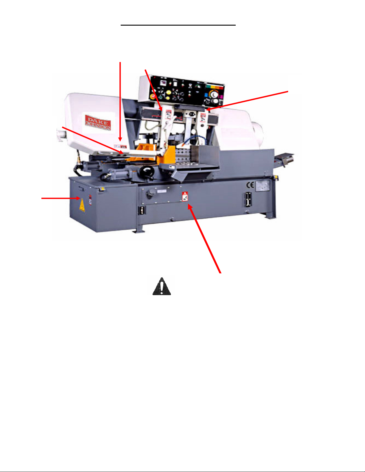
Location of Safety Labels 1.3
1
3
2
4
5
6
SAFETY
be alert to the potential personal injury.
Follow recommended precautions and safe operating practices. Carefully read all
safety messages in these instructions and on your saw safety signs. Keep safety
labels in good condition.
Label 1 – DANGER – KEEP THE COVERS CLOSED WHEN SAW BLADE IS IN
MOTION
Label 2 – DANGER – KEEPS HANDS OFF DURING SAWBLADE OPERATION
Label 3 – DANGER – KEEP BODY PARTS AWAY FROM MOVING PARTS
DURING MACHINE OPERATION
Label 4 – DANGER – DO NOT STEP ON THE ROLLERS ON FEED TRACK
Label 5 – DANGER – THIS MACHINE ELECTRICITY MUST BE LOCKED OUT
BEFORE SERVICING.
Label 6 – DANGER – STEEL TOE SAFETY SHOES MUST BE WORN WHEN
OPERATING THIS MACHINE
12/10/07 Model LE13A Text 6
you see this symbol on your saw,
Page 7

2.1 Machine Life
The intended life limit of this machine is ten years under normal operating
conditions and with good maintenance. The intended life of this machine is
calculated by: 8 hours x 5 days x 52 weeks x 10 years = 20,800 hours.
2.2 Intended Use
The LE10A is an automatic hydraulic band saw machine. It is designed and
constructed for metal sawing only. It is not intended to cut other materials for
example: meat, wood, stone, plastic, Mg and analogous materials.
For safety, it is designed with safety guarding to protect from the moving elements
while operating.
The interlock devices of the wheel guards are hardwired to stop the spindle
revolution of the drive and drive wheel.
This machine has three operation modes:
(1) Automatic Mode
(2) Single Cycle Mode
(3) Manual Mode
It is designed for a trained and skilled person to operate this machine; they must be
trained until they know how to operate it safety.
It is designed that this machine can not be used in a potential explosive
environment.
2.3 Noise Level
The LE13A have a noise level below 75dB (For detailed information, please refer to
the TECHNICAL Section)
SECTION 3
3.1 Transportation
Use a forklift to move the
crated machine. When moving
the machine with a forklift, be
sure the load is safely balanced
personal injury or damage to the
machine can result. Below is the
requirements for lifting:
12/10/07 Model LE13A Text 7
Page 8
Item Metric English
Machine
Weight W
Capacity, T 2 ton 2 ton
Length of the
Fork, L1
Distance
between fork,
L2
1492
meters
meters
Kg
1.5
1.2
LE13A
3,290
lbs
59.06“
47.24”
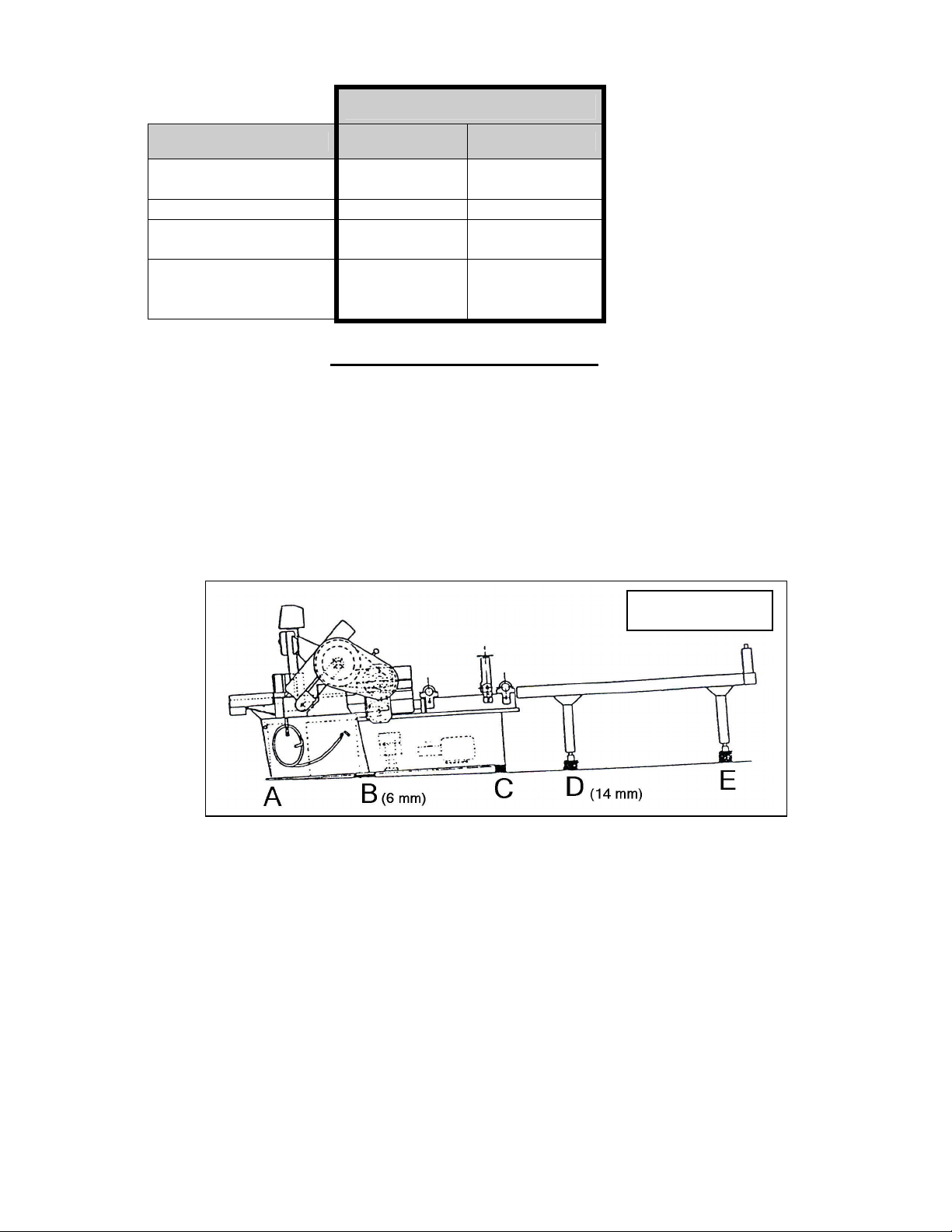
3.2 Preparation for installation
1. LEVELING: It is important to install the machine so that the rear most portion of
the main body table, feed table and roller bed is slightly raised. This prevents
cutting fluid from flowing backward along the material to be cut, especially long
material, and draining on the floor.
See Figure 3.3
Shim section B thicker than section A by 6mm. Shim section D thicker than section
E by 14mm. Horizontally, the table should be level or a little lower on the right.
FIGURE 3.3
If the table is higher on the right, recovery of the cutting oil will be slowed. The
height of the roller table, which is factory-adjusted, need not be re-adjusted. Be sure
the roller table is on the same level as the upper face of the feed table. Use a
straight edge to determine this. The roller face should be level with the feed table or
up to 0.12mm higher.
After the leveling is complete, check to make sure none of the steel sheets fail to
touch the floor due to overload.
REMOVING BRACKET FOR TRANSPORTATION: This bracket must be removed
before operating machine. Keep the bracket for use in moving the machine in the
future.
12/10/07 Model LE13A Text 8
Page 9

This red bracket
must be removed
before the
electrical is
connected.
Figure 3.4
Warning!!!!
Failure to remove this bracket could cause damage to the machine and void the
warranty.
INITIAL OILING: Clean the machine thoroughly. Be sure anti-corrosion additives
applied to sliding parts are removed with cleaning oil. When making a test run refer
to the instructions on 8-1 for proper oiling.
Be sure the cutting fluid is full before operating. This machine was shipped with oil
in it. Use the oil gauge to check oil and cutting fluid level in the machine.
Warning!!!!!
Do not start the motor without oil; damage to the pump will result.
WARNING!!!!
Only a licensed electrician who follows local and state laws is authorized to
connect power to this machine.
The power supply cord will need to come out of the electric box located on the left
side of the machine. Connect power source to the terminals on this cord. Once
connected, turn the main power on (on the left side of machine). The green lamp
should now be on.
Attach grounding terminal located beside the power cord to the factory ground line.
OIL FILL
OIL GAUGE
12/10/07 Model LE13A Text 9
Page 10

CAUTION!!!!!
THE GROUND WIRE MUST BE CONNECTED; FAILURE TO CONNECT THE
GROUND WIRE CAN DAMAGE THE MACHINE AND VOID THE WARRANTY.
Next, make sure the emergency stop button is not activated and that item 4 on
page 11 is to the right. Now press the LIFT button (see picture item 6 on page 11);
lifting starts in one or two seconds after the emergency button is released, the head
continues in the up direction as long as the button is held down. If the head does
not go up, immediately turn the power off, consult your electrician.
3.3 Inspections for Trial Run
After the saw has been installed, this inspection should be performed. The following
checklist will locate any items that may need further attention.
Connect the power (only a qualified electrician)
Coolant fluid is full (only water based coolant)
Hydraulic oil level is full
Check for loose components, guards or panels
Tools and other materials left on saw, remove all tools that are not
part of the machine.
3.4 Environment Requirement
1. Keep the machine on a dry, shaded place to prevent damage to the electrical
components.
2. Storage condition:
Temperature: -20°C 75°C
Humidity: 10% 90%
3. Operation condition:
Temperature: 0°C 55°C
Humidity: 10% 90%
3.5 Dismantle
1. Turn the power OFF.
2. Disconnect the power supply.
3. Drain the hydraulic oil and coolant.
4. Reverse the procedure of installation for this machine.
12/10/07 Model LE13A Text 10
Page 11

15
SECTION 4
12
4.1 Control Panel Description
13 14
16
1
6
7
8
9
2
3
4
1. POWER LIGHT
This light will come on when the circuit breaker is ON.
2. EMERGENCY STOP BUTTON
When this button is depressed, all machine operations will stop.
3. BLADE DRIVE BUTTON
When this button is depressed, the saw blade motor, cutting fluid pump and the
chip removal system will begin to operate and the saw head begins to descend.
The saw head descends quickly until the quick approach arm makes contact with
the work and thereafter, it will descend at the designated cutting speed.
NOTE:
a. On the manual operation, if the front vise is not closed, the saw blade motor
will not operate and saw head will not descend even if the button is
depressed.
b. With the rear vise stop position switch set at
depressing this button will not operate the saw blade motor unless the rear
vise is at the forward limit position. (Manual Operation)
5
11
10
12/10/07 Model LE13A Text 11
Page 12

Front vise
Rear vise
4. AUTO-MANUAL SELECTOR
For Continuous cutting, turn this selector to
To individually operate each function, turn this selector to the hand picture
(MANUAL).
5. QUICK APPROACH BUTTON
When this button is pressed the head will move in the downward position until the
quick approach arm touches the material.
6. RAISE BUTTON
When this button is pressed the blade motor stops and the saw head moves in the
upward position. When the button is released the head will stop moving.
7. VISE CLAMP BUTTON
When this button is pressed and held, one vise will open and the other vise will
close
8. VISE CLAMP SELECTION
When this selector is turned to the left (see picture to the right) with the automanual selector (4) turned to MANUAL the front vise opens and the rear vise
closes; when the selector is turned to the picture (on the lower left of this
paragraph) the rear vise opens and the front vise closes.
(AUTO).
opens
NOTE: On the manual operation, if this selector is
Not turned to the “Rear vice open” the saw blade motor will not operate even if the
drive button (3) is depressed.
9 & 10 REAR VISE FORWARD AND BACKWARD BUTTONS
When the forward button (9) is depressed with the auto-manual selector turned to
“MANUAL” the rear vise moves forward; when the backward button (10) is
depressed, the rear vise moves backward. The rear vise stops moving when the
button is released.
11. CUTTING FLUID PUMP SWITCH
When this switch is set at “|” the cutting fluid pump operates and the cutting fluid will
be on even though the saw blade motor is not in operation. Use this switch when
removing saw chips with the cutting fluid (without the blade operation).
12. CUTTING PIECE COUNTER
This counter is used to press the number of cuts required on the automatic
operation. When the counter reaches the preset number, the machine automatically
stops. To activate the counter, set the counter ON/OFF witch at “| “
opens
12/10/07 Model LE13A Text 12
Page 13

13. Vise shut off switch.
When this switch is off the counter will not work.
14. FEEDING-TIMES PRESET COUNTER
When a cutting length of more than 23” (600mm) is required, preset the required
number of feeds on this counter. The counter is capable of being set to the
maximum of nine feeds. 9*15.74=141.66 (9 x 400mm = 3600mm)
15. WORKING LIGHT
Turn this knob to the left to have the work light on, turn the knob to the right to have
the work light off.
16. REAR VISE STOP POSITION SWITCH
For bundle cutting, set this switch to the multiple picture, so that the rear vise
remains at the forward limit position. For single cutting, set this switch to the single
picture, so that the rear vise stays at the backward limit position.
NOTE: When the switch is set for bundle cutting, the blade will not start
unless the rear vise is at the forward limit positionBLADE SPEED ADJUSTING
BUTTON (Not Shown)
17
18
17. Blade feed
When this control is turned clockwise, the cutting feed is increased. When turned
counter clockwise the feed will decrease. Align the feed control with the zone which
corresponds to the materiel on the work piece to be cut.
18. CUTTING PRESSURE CONTROL & FLOW CONTROL.
When this control is turned clockwise, the cutting force of the saw blade increases;
when it is turned counterclockwise, the cutting force decreases. Align the pressure
control with the zone which corresponds to the material on the work piece to be cut.
12/10/07 Model LE13A Text 13
Page 14

4.2 Blade change
1. Select the saw blade best suited for the work piece to be cut. Size and
shape of the work piece and type of material should all be considered when
selecting the saw blade to be used.
2. Saw blade change.
Warning!!!!!
Always wear gloves, safety glasses and other protective equipment
to prevent injury when changing the saw blade. The power must be
locked out before changing the saw blade.
a. Turn on the main power on the left side of the machine.
b. Press the hydraulic ON button to start the hydraulic pump motor.(item
6 page 11)
c. Turn the auto-manual selector to manual position (the hand item 4
page 11)
d. Press the raise button (item 6 pages 11) to raise the saw head until it
is above the vise.
e. Push the emergency stop button and turn off the main power on the
machine.
Warning!!!!!
Never change the blade with the power on.
f. Remove the blade safety cover.
g. Open both the drive wheel and idle wheel covers.
h. Turn both the left and right insert lock levers counter clockwise to
loosen the inserts.
i. Turn the blade tension selector to “LOOSEN” to move the driven
wheel toward the idle wheel, this will loosen the blade.
j. Remove the band saw blade.
k. Place the saw blade onto both the drive and idle wheels.
l. Insert the saw blade into both the left and right inserts so that the
back edge of the saw blade touches the back-up tip of each insert.
m. To properly position the saw blade on the drive wheel, insert so that
the back edge of the saw blade makes contact with the flange of the
drive wheel.
n. Turn the blade tension handle clock wise to tighten the blade (about
ten clicks)
3. Adjust the position of the wire brush.
a. Loosen the lock lever for the wire brush case.
b. Manually move the brush case so that the wire brush contacts the
saw blade properly.
12/10/07 Model LE13A Text 14
Page 15

4. Properly position the blade guide according to the diameter (or the width) of
the work piece to be cut.
a. Pull the left insert lock lever down to loosen the insert.
b. Loosen the lock lever of the blade guide, and manually move the
blade guide and align the indicator of the blade guide with the scale
of the guide bar, depending upon the size of the work piece.
c. After adjusting the blade guide position tighten the lock lever of the
blade guide.
d. Push the insert lock lever up to tighten the insert.
4.3 Manual Operation Instructions
MANUAL OPERATION
1. Properly place the work piece on the work feed table.
e. Depress the raise button to raise the saw head until it is at the highest
position.
f. Manually disengage the pawls from both the front and rear vise racks,
and open the front and rear vise completely.
g. Loosen the lock handles of the vertical roller guides to completely
open the vertical roller guides.
h. Set the rear vise stop position switch so that the rear vise stays at the
backward limit position.
i. Carefully place the work piece onto the work feed table so that is
extends approximately 2.5” (60mm) beyond the rear vise.
2. Determine the proper position of the work piece for cutting.
j. Turn the vise clamp selector to “rear vise open”.
k. Manually move the rear vise until it pushes against the work piece.
Then engage the pawl with the rack.
l. Turn the vise clamp selector to “front vise open”, so that the work
piece is securely clamped with the rear vise.
m. Push the vertical roller guides against the work piece and tighten the
guides with the lock handles.
n. Depress the rear vise forward button until the rear vise moves to the
forward limit position.
o. Manually move the front vise until it pushes against the work piece
then engage the pawl with the rack.
p. Turn the vise clamp selector to “rear vise open” so that the work
piece is securely clamped with the front.
q. Depress the rear vise backward button until the rear vise moves to
the backward limit position.
r. Turn the vise clamp selector to “front vise open”.
s. Lower the saw blade by depressing the quick approach button, until
the quick approach feeler is just above the work piece.
t. Depress the rear vise forward button to move the work piece forward
until the cutting position of the work piece is aligned with the saw
blade. If necessary, press the rear vise backward button so that the
work piece is accurately positioned.
12/10/07 Model LE13A Text 15
Page 16

u. After properly adjusting the position of the work piece, turn the vise
clamp selector to “back vise open”, so that the work piece is securely
clamped with the front vise.
v. Adjust the blade speed to the proper speed section 4.4
w. Turn on the coolant by turning the coolant switch. The flow of cutting
fluid should be adjusted, depending upon the material.
x. When the blade drive button is pressed, the cutting fluid pump begins
to operate causing the cutting fluid to flow out the coolant lines. Adjust the
cutting fluid flow with the fluid controls so that the proper amount of fluid will flow
from the blade inserts, the quick approach and the wire brush case.
Saw chips which are fine and curve require an increase in the amount of
cutting fluid.
Saw chips which are fine and grained require a reduction in the amount of
cutting fluid.
5. Adjust both the cutting force and the descending speed of the saw blade and
begin cutting the work piece by pushing the green blade drive button.
a. Turn the cutting pressure control (page 13 for description) to the zone
corresponding to the material (or shape) of the work piece to be cut.
When the work piece is large (or difficult to cut), turn the control to the
right end of the corresponding zone. When the work piece is small (or
easy to cut), turn the control to the left end of the corresponding zone.
Always turn the cutting pressure control to the point most suitable for
the work piece to be cut.
b. Slowly turn the feed control clockwise from zero to the point just
before the blade begins to vibrate. As the flow control is turned, the
saw blade begins to descend and the actual cutting of the work piece
begins. After completion of the cutting, the saw blade stops at the
lower limit position.
4.4 Automatic operation instructions
Set part length (section 4.6). Follow instructions for manual operation. The only thing
that will be different is after you push the green start button turn the manual /
automatic switch to automatic (see section 4.1).
Warning!!!!!
Always turn the machine power off before changing the blade
speed.
12/10/07 Model LE13A Text 16
Page 17

4.5 Blade speed change
3. Adjust the saw blade speed.
c. There is a handle just to the right of the motor, when loosened the
motor can be moved up and down. Move the motor up and move the
belt to the desired speed.
d. It is necessary to properly adjust the saw blade speed, depending
upon the material and shape of the work piece to be cut.
e. The blade drive uses a V-Belt: A-47 (60 Hz) and A-48 (50 Hz).
Blade speeds are 27, 40, 54, 68 and 80m/min
4.6 Part length set up and automatic operation
How to set the required cutting length on the cutting length counter.
WARNING!!!!!
Do not change the numerals (number of feeds) on the feeding times
preset counter during operation.
a. Loosen the hand-wheel lock screw.
b. Turn the hand-wheel to set the required cutting length on the cutting
length counter.
12/10/07 Model LE13A Text 17
Page 18

NOTE:
1. When setting the cutting length, be sure to turn the hand wheel
clockwise past the desired length, then turn it counter clock wise to
the desired length to prevent error due to the backlash.
c. Tighten the hand-wheel lock screw
Hand wheel
4. If the required cutting length exceeds the maximum cutting length of 23.6 inches
(600mm), feed the work piece as many times as necessary, using the feed
times preset counter (item 14 page 11). For example: if a cutting length of 31.5
inches (800mm) is required.
a. Divide 31.5 by 2 =15.75
b. This will be the length of cut needed to make 31.5 inches.
c. Set the feed times counter at 2.
d. Now the material will be pushed forward two times, each time moving the
material forward 15.75 inches.
NOTE:
i. The cutting length preset device is factory adjusted to compensate
for the set width of the saw blade.
ii. When the feeding times preset counter is not in use, set it a 1.
iii. The feeding times preset counter is capable of feeding the work
piece nine times, up to a maximum cutting length of 212.5 inches
(5400mm).
5. How to set the number of required cuts on the cutting piece counter.
Warning!!!!!
Do not change the number of cuts during cutting operation.
a. Set the cutting piece counter switch (item 12 page 11) at “o” (OFF).
b. Press the reset button (on the bottom of the readout) to reset all white
numerals to zero.
c. On the top of this read out there are five black buttons, each button is a
different digit. Push these buttons to desired amount of pieces to be cut.
d. After the number of cuts has been set.
e. Set the counter ON/OFF switch at “| “(ON).
12/10/07 Model LE13A Text 18
Page 19

6. Turn the auto-manual selector to AUTO and press the blade drive button. The
blade will run and the automatic operation will begin.
7. After the required number of cuts have been completed, the saw blade will stop
in the lower position and all machine operations will stop.
NOTE:
i. During automatic operation, shifting the auto-manual selector to
MANUAL will cause the saw blade to stop in the lower position,
after completion of the cutting operation on which the selector was
shifted.
NOTE:
If the machine does not start be sure the vise switch (item 8 in the control panel
description) is turned to the left.
4.7 How to install bundle attachments
How to use the bundle cutting attachments
WARINING!!!!!
Never install the bundle attachments while the machine is in
operation. This machine electricity must be locked out before
installing bundle attachments.
WARNING!!!!!
Keep fingers clear of vise, personal injury could occur.
This multi-vise is used when bundle cutting is performed. To perform bundle cutting,
proceed as follows:
1. Install the stud bolts on the front and rear vises and position the multi-vise on
the front and rear vises.
2. Connect the multi-vise hoses to their quick connectors at the front and rear vise
cylinders.
3. Attach the bundle cutting fence to the work tray. The fence is designed to
prevent the cut pieces from spreading out across the work tray. Adjust the width
of the fence so that it equals the width of the bundle.
12/10/07 Model LE13A Text 19
Page 20

4. Set the switch to bundle cutting (item 13 pages 11).
CORRECT
INCORRECT
5. Position the work piece for bundle cutting.
Allowable clamping width: 7 inches (180mm)
6. Roughly align the center of the multi-vise cylinders with the center of the work
pieces to be cut and tighten the lock nuts.
7. Turn the multi-vise handles so that there is 1/4” of clearance between the work
retaining plate and the material.
8. For subsequent operations, refer to the instructions for manual operation and
automatic operation, and perform the bundle cutting.
EXAMPLE:
BLADE BREAK IN OPERATION
When a new saw blade is used, be sure to first break in the blade before using it for
actual extended operation. Failure to break in the blade will shorten the life of the
blade and result in less than optimum efficiency. To break in the blade, proceed as
follows:
1. Lengthen the time required for cutting 2-3 times that of normal.
12/10/07 Model LE13A Text 20
Page 21

2. The break-in operation can be considered sufficient if all unusual noises
or metallic sounds have been eliminated. (For instance, to completely
break in the blade, a minimum of five complete cuts of a 200mm (7.9 in)
diameter work piece will be required.)
3. After the break-in operation has been completed, return the blades speed
and descending speed to their normal settings
4.8 Cutting Data
12/10/07 Model LE13A Text 21
Page 22

6.2 Lubrication
Description
Hydraulic Oil DTE 24 Hydraulic oil
Gearbox Oil 80/90 Synthetic gear lube
Drive wheel Shell Alvania EP Grease 2 or Mobilplex 48
Idle Wheel Shell Alvania EP Grease 2 or Mobilplex 48
Blade Tension Device Shell Alvania EP Grease 2 or Mobilplex 48
Worm Shaft Shell Alvania EP Grease 2 or Mobilplex 48
Cutting Fluid Water based coolant
Lubricant
Section 7 – MAINTENANCE
7.1 Periodic Maintenance
After use for the day, clean out saw chips that have accumulated in the machine. To do
this, set the cutting fluid pumps switch at “|”and wash saw chips away with the discharging
cutting fluid.
Before beginning operation for the day, perform the following maintenance operations:
1. Check the hydraulic oil level, adding oil if necessary.
2. Check the cutting fluid level, adding fluid as
necessary. If the fluid appears contaminated or
deteriorated, drain and replace it.
3. Check the saw blade to ensure that it is properly
positioned on both the drive, idle wheels and in the left
and right inserts.
4. Check the wire brush for proper contact with the saw
blade. If it is worn, replace.
5. Check the urethane rope (used on the idle wheel) for
Grease Fittings
wear. If they are broken, replace.
6. Lubricate the following points:
a. Front vise slide plates
b. Rear vise slide plates
c. Feed cylinder guide shaft.
7.2 Six Month Maintenance
Check the following once every six months:
1. Clean the filters in the cutting fluid tank.
2. Replace the transmission oil (recommended oil: 80/90
synthetic) after the first three months or 600 hours of
operation and every six months or 1200 hours of
operation (whichever occurs first) thereafter.
3. Replace the hydraulic oil.
12/10/07 Model LE13A Text 22
Page 23

SECTION 8 – TROUBLE SHOOTING CHART 8.1
Machine has power but will not start cut in Semi-Auto mode
Vibration during cutting or excessive noise
Yellow warning light flashes
Material will not feed
Blade cuts crooked or unsure
Hydraulic pump runs when head button pushed but machine will not run
Will not cut in automatic mode
Will not cut to length set on digital readout
Blade Stalls in cut
Use of blade with incorrect pitch. Call blade supplier.
Failure to break in blade. Perform break-in (first 12 cuts 1/3 slower
than normal cut rate).
Excessive blade speed. Reduce speed.
Insufficient blade speed. Increase blade speed.
Excessive chip load (blade loads up
with chips, too fine).
Wire chip brush worn/improperly
adjusted.
Blade improperly held by insert.
Carbide pads too loose.
Roller table in true alignment with
feeder unit.
Belt slipping stalling blade. Belt is loose on pulley. Loosen motor
Guide arms set too far apart. Move guide arms closer together. Use
Limit switches on doors and pulley
(open).
Fuse blown in machine or wall
service.
Insufficient blade tension. Tighten blade a half to a full turn beyond
Out of stock or end of program Estop pushed in.
Blade too narrow/too wide (out of
capacity) too long.
Coolant mixed incorrect, or no
coolant used.
Front vise not closed. Jog the vise selector switch and bump
Zero parts entered in piece counter
or zero strokes.
Not in automatic mode. Reset
piece counter bottom button.
Part moved during cut. Check clamping of part. Use bundle
Movement detector on idle wheel
out of adjustment.
Length set up wheel backed up
during set up.
Reduce load cut slower or coarser blade,
adjust chip brush for cleaning blade.
Readjust or replace (just touch blade).
Tighten the 2 knurled knobs on guide
arms as tight as possible to reduce pad
clearance, or replace.
Not set straight to machine feed system.
Sits too high or low to the feed roller.
Adjust
lock handle, push down on motor and
tighten. Replace belt is worn.
indicator marks on guide arm rail for
proper spacing.
Check all doors are closed. Check limit
adjustment, make sure cotter pin is not
interfering with limit activation.
Check and replace fuses as needed.
when tensioner lock ring clicks.
Press reset button on counter. Make
sure you have stock. Reset number of
pieces in counter check E-stop.
Use only blade within cap. .035-.045
thickness. Use blade or correct length &
width.
Mix coolant to manufactures specs. (10-
1) Increase coolant flow.
vise close button. This will close vises.
Reset # in piece counter. Must have at
least 1 stroke entered. Out of stock limit
tripped. Feed limit failure.
Reset piece counter. Check that
machine is in automatic cycle. Vises are
closed.
cutting option for multiple piece cutting.
Adjust red LED illuminates as wheel
passes by it.
Set to length without going beyond
length, and backing up. Backlash is
screw will cause
12/10/07 Model LE13A Text 23
Page 24

8.1 Minor trouble shooting
Symptom Probable Cause Corrective Action
Hydraulic pump motor
does not run even
though hydraulic on
button is depressed.
Saw blade motor does
not run even when
blade drive button is
depressed.
a. Power line disconnected
b. Circuit protector OFF
c. Thermal relay activated
d. Loose terminal retaining
e. Out-of-stock limit switch
a. Terminal relay activated
b. Vise clamp selector set at
c. Rear vice stop position
screw
activated
switch
set at
a. Connect
b. Turn ON
c. Push reset button
d. Tighten
e. Set vise clamp selector at
a. Push reset button
b. Set vice clamp selector at
c. Move rear vise to its
forward limit position
(when performing bundle
cutting)
d. Set rear vise stop position
switch at (when
performing single cutting)
Rear vice does not
move forward or
backward even when
its forward or
backward button is
depressed.
Front or rear vise does
not open or close even
though vise clamp
selector is manipulated
For problems not indicated on the above chart, refer to the electrical circuit and
hydraulic circuit diagrams (provided inside the electrical enclosure).
a. Auto-Manual selector set at
b. Saw head not at its UP
position
a. Auto-Manual selector set at a. Change auto-Manual
a. Set auto-manual selector
b. Raise saw head to its UP
position
selector setting.
For original Dake replacement parts contact us at:
DAKE Division of JSJ
724 Robbins Road
Grand Haven, MI 49417
Phone: 1-800-937-3253 616-842-7110
Fax: 1-800-846-3253 616-842-0859
E-mail: customerservice@dakecorp.com
technicalservice@dakecorp.com
Web: www.dakecorp.com
12/10/07 Model LE13A Text 24
 Loading...