

Page 1

*** PLEASE NOTE****
This manual is for Dake Johnson manufactured J & JH horizontal bandsaws from 1985 to
current.
If your model is prior to 1985, please contact the factory for manual and parts information.
1938 - 1965 Johnson manufactured J saws.
1965 - 1984 Kysor/Johnson manufactured J & JH saws.
6/02
1
Page 2
Operator’s Manual and Part’s List
Model J-10 & JH-10
Dake/Johnson Horizontal Bandsaw
6/02
DAKE Division of JSJ
724 Robbins Road
Grand Haven, MI 49417
Phone: 1-800-937-3253 616-842-7110
Fax: 1-800-846-3253 616-842-0859
E-mail: customerservice@dakecorp.com
technicalservice@dakecorp.com
Web: www.dakecorp.com
2
Page 3

6/02
FOREWORD
This manual has been prepared to acquaint you with the operation, maintenance, and
serviceable components of your Dake/Johnson machine. We urge that you read it carefully
before operating your machine. Please refer to the pertinent sections when contacting the
factory regarding parts, schematics…or when you have other questions.
As Dake’s policy is one of continuous development for each range of machine, the contents
of this manual, though completely up to date when issued, are subject to change without
notice.
For your information and future reference, pertinent data concerning your machine may be
inserted in the space provided below.
Machine Model ___________________________
Serial Number ___________________________
Date Received _________________
Voltage ___________________________
Phase _______ Cycle _______ Motor H.P. ______
Please give the machine model and serial number in correspondence, and include the parts
numbers on parts orders to speed the filling of your requirements and to minimize your
inconvenience.
FACTORY: DAKE Division of JSJ
724 Robbins Road
Grand Haven, MI 49417
Phone: 1-800-937-3253 616-842-7110
Fax: 1-800-846-3253 616-842-0859
E-mail: customerservice@dakecorp.com
technicalservice@dakecorp.com
Web: www.dakecorp.com
NOTE: Use only genuine Dake/Johnson replacement parts and optional equipment. Use of
substitutes or imitations may cause damage to the machine, void the warranty, and may
cause injury.
3
Page 4

CONTENTS
GENERAL
Basic Machine Data ……………………………………. 4
Specifications …………………………………………….. 4
Machine Installation ……………………………………… 4
Safety Information………………………………………… 5-6
Electrical Diagrams ………………………………………. 7-9
Machine Features ……………………………………….. 10
SECTION 1
OPERATION
Controls and Operation ………………………………….. 11
Standard Drive …………………………………………… 12
Blade Selection ………………………………………….. 13
Blade Removal/Installation ……………………………… 13-14
Blade Guide Adjustment ………………………………… 14-15
Balance Spring Adjustment …………………………….. 15
Feed Cylinder Bleeding …………………………………. 15
SECTION 2
MAINTENANCE
Lubrication ………………………………………………… 16
Sawing Problems and Solutions ………………………… 17
SECTION 3
ASSEMBLIES & PARTS LISTS
Machine Assembly (Front View) ………………………… 18-19
Machine Assembly (Top View) ………………………….. 20
Gear Box Assembly ………………………………………. 21
Hydraulic Assembly ………………………………………. 22-23
Guide Arm Assembly ……………………………………... 24
Vise Unit ……………………………………………………. 25
6/02
4
Page 5
6/02
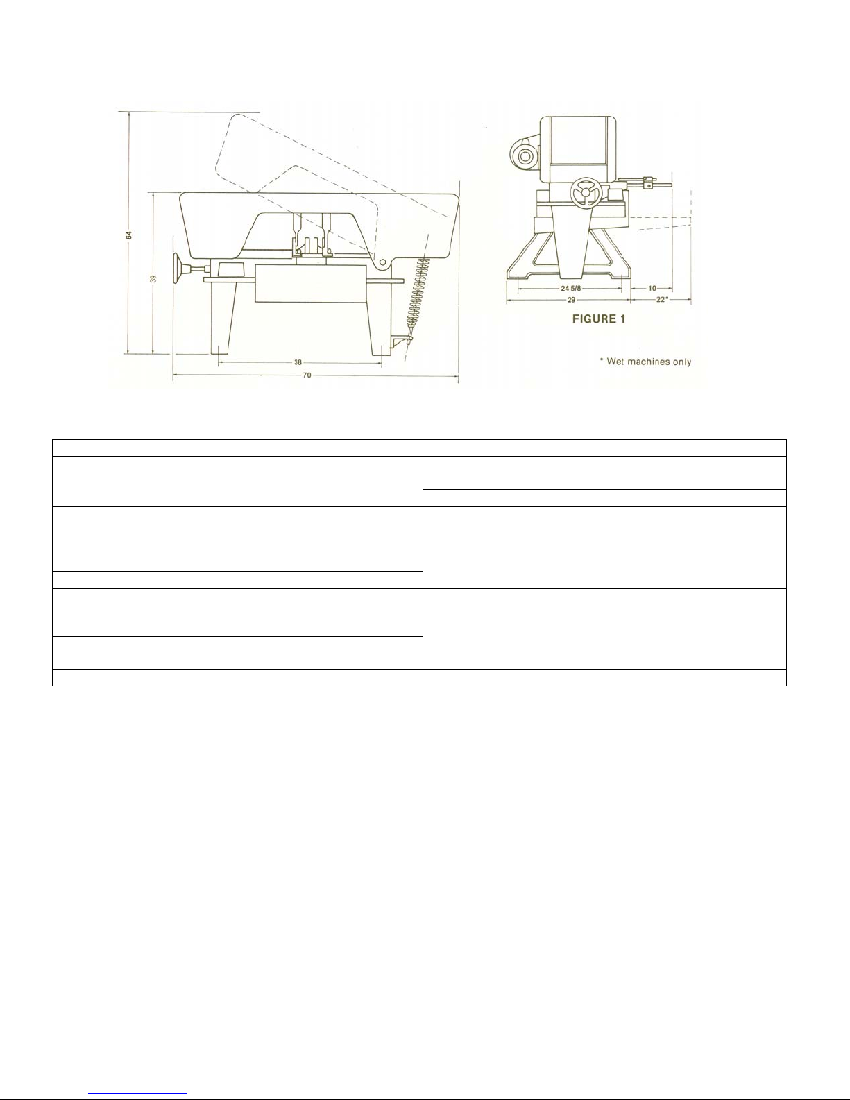
BASIC MACHINE DATA
SPECIFICATIONS
Capacity………...10” (25cm) rounds, 18” (46cm) flats Floor Space ……………… 29” (74cm) x 70” (178com)
Blade Size (Part Numbers: 75958 (3/4”) OR 75957 (1”) Height, Closed* …………………………….. 39” (99cm)
J-10 ……………………… ¾” (2cm) x 137” (348cm) Height, Open* ……………………………... 64” (163cm)
JH-10……………………... 1” (3cm) x 137” (348cm) Floor to Bed* …………………………….. 23 ¾“ (60cm)
Blade Speeds Net Weight
………………………………50, 90, 160 and 270 fpm J-10 Dry …………………………. 812 lbs (368 kgs)
………………………………..15, 29, 49 and 82 mpm J-10 Wet ..……………………….. 845 lbs (383 kgs)
Bed Work Area. ……..……… 11” (28cm) x 18” (46cm) JH-10 Dry ……………………..… 817 lbs (371 kgs)
Vise Size ………………………. 5” (13cm) x 11” (28cm) JH-10 Wet ……………………….. 850 lbs (386 kgs)
Drive Motor Gross Weight
J-10 ………………………………….…. 1 hp (.75kw) J-10 Dry …………………….…… 896 lbs (406 kgs)
JH-10 …………………………………... 1 hp (.75kw) J-10 Wet ……………………..….. 929 lbs (409 kgs)
Electrical System, specify …....110/230V, 1 PH, 60 Hz JH-10 Dry …………………..…… 901 lbs (409 kgs)
208/230/460V, 3 PH, 60 Hz JH-10 Wet ..……………………….934 lbs (424 kgs)
Coolant Capacity …………………………...… 3 gallons Water-soluble only – do not use oil.
INSTALLATION
UNCRATING :
machine has been moved to its approximate location.
CAUTION: BE SURE ELECTRICAL CHARACTERISTICS OF MOTOR AND SWITCH
CORRESPOND WITH ELECTRICAL POWER SUPPLY.
!!!ATTENTION!!! DO NOT ATTEMPT TO RUN THIS SAW UNTIL THE BLADE ALIGNMENT HAS
BEEN CHECK AS PER THE OWNER’S MANUAL AND THE BLADE HAS BEEN PROPERLY RETENSIONED.
LEVELING: Position machine reasonably level, shim under legs if necessary. Wet machines
should be more carefully leveled to be certain that the coolant intake remains submerged.
CONNECT INCOMING POWER TO THE STARTER PER APPLICABLE DIAGRAM, AND IN
ACCORDANCE WITH ALL LOCAL CODES.
Remove crating carefully. For ease in handling do not remove from skid until
5
Page 6

SAFETY INFORMATION
LABEL
84605
LABEL
84604
LABEL
84395
LABEL
76462
LABEL 84605 – SAFETY INSTRUCTIONS
6/02
SAFETY
This is the safety alert symbol. When
you see this symbol on your saw, be alert to
the potential for personal injury.
Follow recommended precautions and safe
operating practices. Carefully read all safety
messages in these instructions and on your saw
safety signs. Keep safety labels in good
condition. Replace missing or damaged safety
labels.
6
Page 7

LABEL 84604 – SAFETY INSTRUCTIONS LABEL 84395 – DANGER LABEL
LABEL 84604 – WARNING
Follow recommended precautions and safe operating
practices. Carefully read all safety messages in these
instructions and on your saw safety signs. Keep safety
labels in good condition. Replace missing or damaged
safety labels.
6/02
SAFETY
This is the safety alert symbol. When you see this
symbol on your saw, be alert to the potential for
personal injury.
7
Page 8
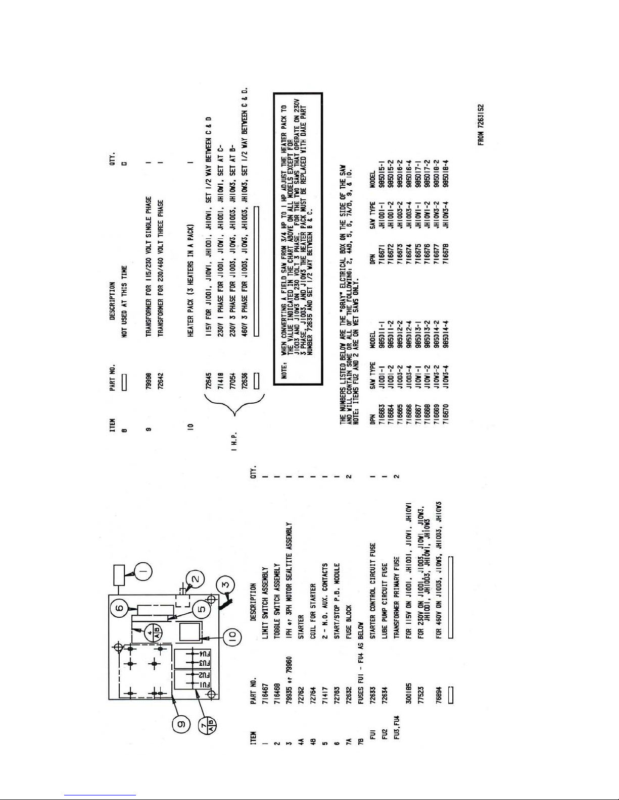
ELECTRICAL CONTROL DIAGRAMS
6/02
8
Page 9
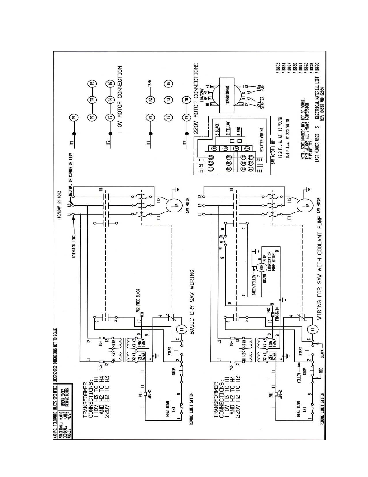
SINGLE PHASE ELECTRICAL DIAGRAM
6/02
9
Page 10

THREE PHASE ELECTRICAL DIAGRAM
6/02
10
Page 11
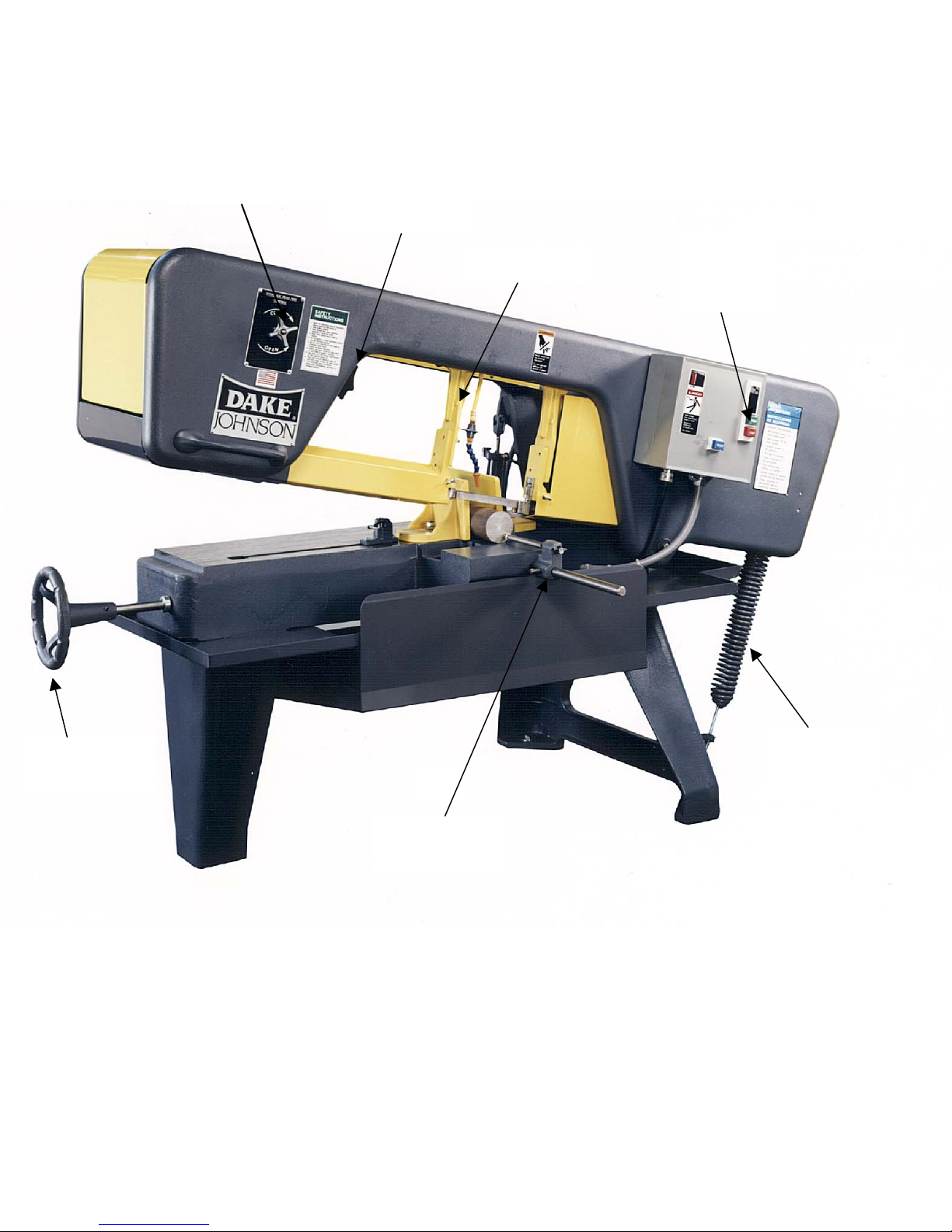
Vise
Handwheel
Head Feed
Control
MACHINE FEATURES
Blade
Tension
Handle
Guide Arm
Stock
Stop Gauge
SECTION 1
6/02
Off-On
Switch &
Starter
Balance
Spring
11
Page 12

OFF/ON SWITCH
All J-saw machines are equipped with a manual starter with low voltage, dropout protection
and a limit switch. When the machine frame reaches the end of its down travel it contacts the
limit switch, turning off the machine.
HYDRAULIC CONTROL
The hydraulic control cylinder mounted on the rear of the machine is operated by a control
valve mounted on the front of the machine head. To close valve, turn the control to the right.
When the valve is completely closed, the frame will remain stationary at the desired position.
To open valve, turn control to the left. Opening of the valve will control the speed of descent
of frame (or head) and does not control frame weight. This control is mainly used in cutting
pipe or thin-walled tubing, structurals, etc., to prevent plunging of the saw blade.
VISE
The vise can be positioned straight for a 90º cut or at any angle to 45º. The vise swivel jaw
adjusts automatically to any position of the stationary jaw.
VISE QUICK-RELEASE
Consists of the vise half-nut, vise lift, lift handle and a sliding hold-down block to which the
swivel jaw is attached. Move the vise lift handle toward front of the machine to disengage the
vise nut from the vise screw; this allows the swivel jaw to be moved freely. Move the lift
handle towards the rear of the vise to engage the vise nut when clamping.
VISE HANDWHEEL
Used to open and close the vise jaws…vise nut must be fully engaged. Turn handwheel
counterclockwise to open the vise, clockwise to close the vise.
BLADE TENSION HANDLE
Turn the screw handle clockwise as tight as possible. Check every eight operating hours and
retighten to compensate for possible stretching of blades. Consult your blade manufacturer
for the proper PSI tension.
GUIDE ARMS
Loosen the handle on the left guide arm to slide arm along the top of the frame. Guide arms
should be set as close as possible to the work, without interfering.
STOCK STOP GAUGE
Consists of a stock stop assembly and a mounting bar installed in the tip-off block on front of
the machine. The stop assembly can be moved along the bar to indicate correct length for
duplicate cuts. Stock stop rod has a cap screw in the end for making fine adjustments. Turn
rod to extended position (rotated to the right) when measuring stock, and retract the rod
(rotate to left) when cutting.
OPERATING INSTRUCTIONS
6/02
OPERATION
12
Page 13

6/02
1. Raise frame and close feed cylinder valve to hold frame in elevated position.
2. Loosen the vise nut and open the vise. Place work in vise and slide the vise swivel jaw
against the work piece. Engage the vise nut and tighten the vise screw to clamp the work
securely.
3. Slowly open feed cylinder valve and lower the frame until the blade almost touches the
work. CAUTION: IF BLADE SHOULD REST UPON THE WORK BEFORE MOTOR IS
STARED THE BLADE TEETH CAN BE DAMAGED- IF BLADE IS DROPPED ONTO THE
WORK THE BLADE MIGHT BREAK. MAKE SURE BLADE IS PROPERLY BROKEN IN
PRIOR TO CUTTING.
4. Move the adjustable guide arm as close as possible to the work to provide maximum
blade rigidity.
5. Check the blade tension. Consult blade manufacturer for proper PSI tension.
6. Turn coolant valve on (wet machines only). CAUTION: DO NOT OPERATE MACHINE
WITHOUT SUFFICIENT COOLANT IN TANK. COOLANT MUST BE WATER-SOLUBLE
DO NOT USE OIL.
7. Check blade speed for material you are cutting. Refer to blade manufacturer for proper
speeds for the material you are cutting.
8. To change blade speed, loosen thumbscrew on right end of machine and raise the pulley
guard. Move drive belt to proper grooves in both pulleys for desired blade speed, (see fig. 3).
Replace guard.
9. Start motor.
10. Open feed cylinder valve to the proper setting. “Proper” setting depends upon type of
material, hardness and thickness of stock and desired accuracy and finish. Soft materials
require less feed than hard materials. Thin cross-sections require less feed than solid crosssections. Generally, reduced feed pressure will result in a straighter more accurate cut.
13
Page 14

6/02
BLADE SELECTION
Saw blades should be selected by choosing the blade that will give the best results at the
lowest cost. Type of material and the speed at which it must be sawed determine the choice.
Listed below are general factors affecting blade selection.
1. Blade Type.
(a) Carbon Steel – Can be used to cut all types of ferrous, non-ferrous and
composition materials except alloys containing high percentage of chrome and
nickel. Limiting factor: low resistance to heat.
(b) Bi-Metal – Designed for cutting ferrous metals in production cut-off
applications. Developed to saw high alloy materials that cannot be cut
economically by other means. Can be operated at higher speeds and greater
feed pressures than carbon steel blades.
2. Tooth Style.
(a) Standard – Zero degree rake angle and full round gullets. Best suited for
cutting ferrous and non-ferrous materials.
(b) Skip Tooth – Basically the same as standard except for more widely spaced
teeth. Provides added chip room when cutting non-ferrous materials.
(c) Hook Tooth – Similar to skip tooth except teeth have positive rake. Effective
in sawing non-ferrous metals and large ferrous sections when heavy feed
pressures are required. Fast cutting.
3. Tooth Spacing.
Tooth spacing is determined by hardness of material and/or the cross-section.
The harder the material, the more teeth per inch. Thin cross-sections require
more teeth to avoid straddle. Rule: at least 3 teeth in contact with work.
4. Tooth Set.
(a) Raker – Most widely used. Consists of a repeated pattern of one tooth set
left, one right and one tooth straight. Recommended for production cutting
where material is of uniform size, shape and type.
(b) Wavy – Has groups of teeth set alternately to the left and to the right forming
a wave-like pattern. Used for cutting thin stock or where the work varies such
as in pipe, angles, channels and extrusions.
BLADE REMOVAL
1. Raise frame a few inches above bed and close feed cylinder valve to hold frame up.
2. Remove necessary guarding and blade cleaning brushes.
3. Turn blade tension screw counterclockwise and pull idle wheel toward center of machine.
4. Push blade down out of blade guides and remove blade from machine.
BLADE INSTALLATION
14
Page 15
6/02
1. Raise frame a few inches above bed and close feed cylinder valve to hold frame up.
2. Remove necessary guards and blade cleaning brushes.
3. Turn blade tension screw counterclockwise and pull idle wheel toward center of machine.
4. Grasp blade in center forming two loops. From rear of machine place blade loops under
wheels and rest the near portion on right front blade guard. CAUTION: BE SURE TO
WEAR GLOVES WHEN HANDLING BLADES.
5. Push blade up into blade guides. CAUTION: BE AWARE OF HYDRAULIC & COOLANT
LINES.
6. Fit blade up against flanges of the idle and drive wheels and tighten tension screw enough
to hold blade in place. Depress side of blade near rear blade guard to hold blade on
wheels while tightening tension screw.
7. Check to see that the blade is positioned correctly and tighten screw. Consult blade
manufacturer for proper PSI tension.
8. Install blade cleaning brushes and guards that were removed earlier.
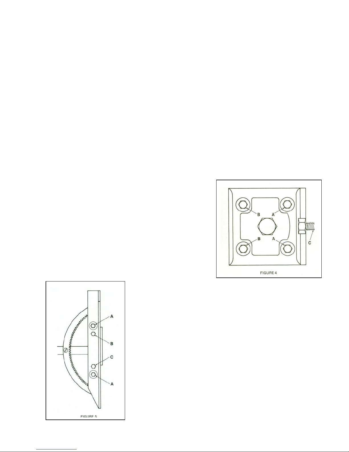
BLADE TRACKING ADJUSTMENT
Saw blade should track on each wheel with the back of blade up to, but not riding on, the
wheel flange. Adjust as follows:
1. Idle Wheel.
Open top cover on left end of machine to gain
access to idle wheel. Idle wheel is mounted on a
slide block, which contains the blade height
adjustment screws. To raise the blade, loosen the
two screws toward center of machine (A, Fig. 4)
one-half turn and tighten the other two screws (B)
one-half turn. Be sure tension screw (C) is properly
tightened. Reverse procedure to lower blade. Care
must be taken not to over adjust. Check by running
machine after each adjustment.
2. Drive Wheel.
(a) To raise the blade, loosen two cap screws (A, Fig. 5) and
tighten screws (B and C). All four screws must be turned
equally and in small increments (about ½ turn) to avoid overadjustment; check by running machine after each adjustment.
(b) To lower blade, reverse above procedure – loosen screws
(B and C) and tighten screw (A).
15
Page 16
6/02
E
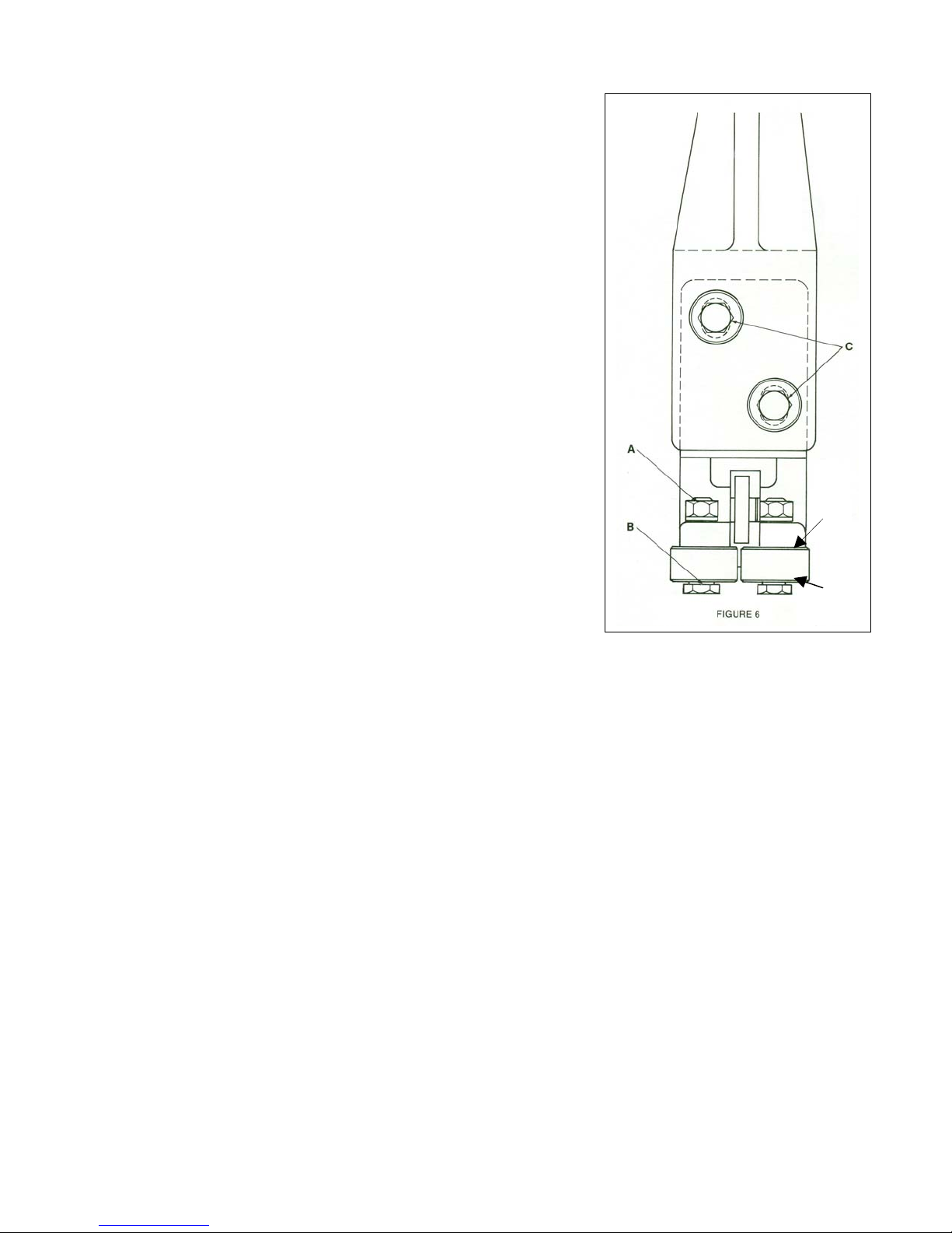
BLADE GUIDE ADJUSTMENT
NOTE: The following instructions are for one
guide arm; procedure is same for both. Left hand
guide arm is shown in Figure 6.
1. Loosen nut (A, Fig. 6) and turn eccentric axle (B)
until there is no light gap between rollers and
blade…do not pinch the blade. Tighten nut (A).
2. Vertical and radial adjustment is provided by the
clearance in the guide mounting holes (C, Fig. 6).
This allows squaring of the blade to the bed, and
holding the blade in the natural blade line.
3. Proper guide adjustment may require adding or
removing washer (shims) (D, Fig. 6) for correct
bearing height (E, fig. 6)
D
FRAME BALANCE SPRING ADJUSTMENT
To check for proper balance spring adjustment, lift frame at eh handle with an extension type
scale (fish scale). Frame should weigh 12-15 pounds; if no, adjust by turning nut on the tension
screw at bottom of spring.
FEED CYLINDER BLEEDING
Air trapped in the hydraulic cylinder can cause the down feed of the machine head to be
erratic or “bouncy”. Before taking corrective steps observe CAUTION.
CAUTION: UNDER NO CIRCUMSTANCES SHOULD THE HYDRAULIC TUBING CONNECTIONS
BE LOOSENED OR DISCONNECTED WITH THE MACHINE HEAD IN THE UP POSITION.
Bleed the hydraulic cylinder circuit as follows:
1. Place a long neck funnel in the oil cup (diameter of funnel neck must be almost the same
size of the fill cup.
2. Pour oil into the funnel. *Make sure there is a sufficient amount of oil in the funnel so that
air does not get drawn into cylinder.
3. With head feed valve open, raise and lower head about four times.
4. Pour more oil into the funnel.
5. Close head feed valve.
6. Raise head.
7. Open feed valve and lower head.
8. Repeat 5,6 & 7 several times.
9. Remove funnel.
16
Page 17
MAINTENANCE
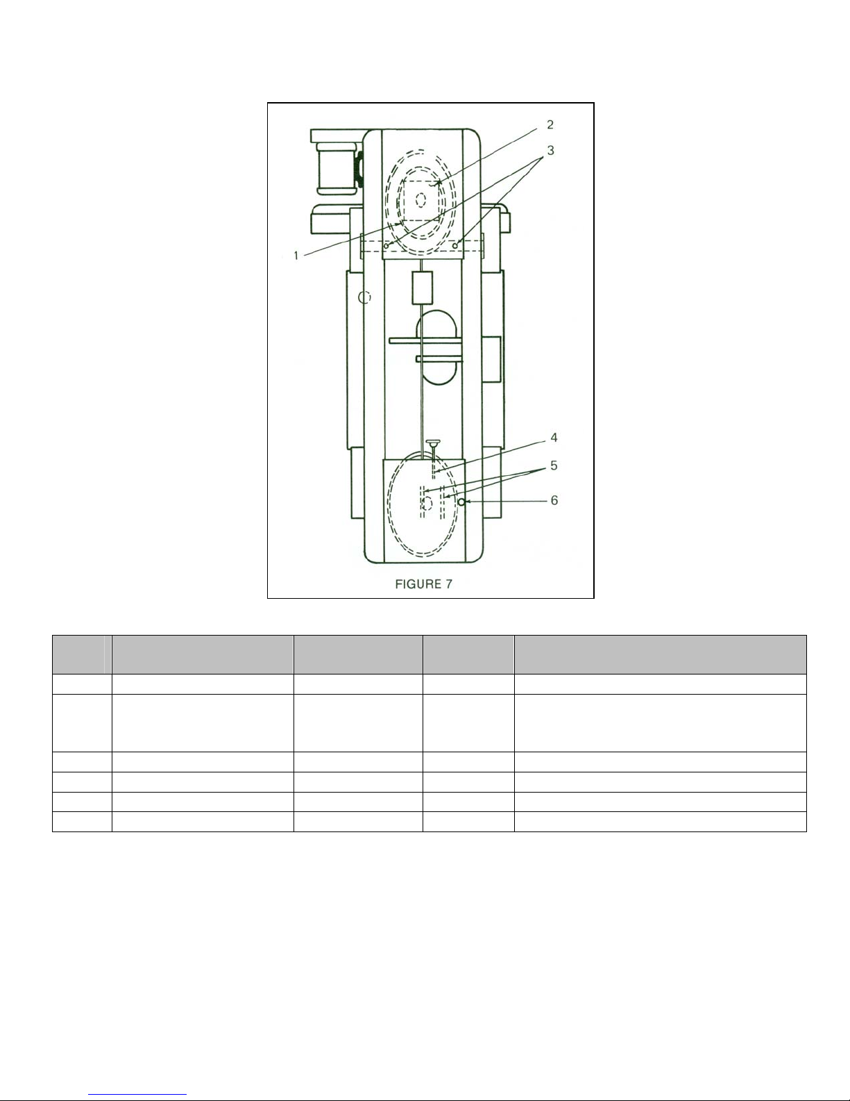
LUBRICATION
Lube
Point
1 Drive wheel ring gear 6 months
2 Gear box Maintain level
3 Pivot bar (2 fittings) Monthly
4 Tension screw 6 months
5 Idle wheel slide ways 6 months
6 Feed cylinder Maintain level
A – Mobil DTE 24 or 26 oil. Viscosity range 310SSU @ 100ºF.
B – Gear oil 80/90. Mobil SHC635 synthetic gear lube.
C – General purpose grease. Viscosity range NLGI-2.
D – Open gear lubricant.
Description
RECOMMENDED LUBRICANTS
Interval
Lubricant
D
B
C
C
C
A
Instructions
Clean thoroughly before lubricating.
Maintain level at 2 to 3 ounces.
Drain and refill yearly. Capacity 3
ounces.
Use grease gun.
Clean threads before lubricating.
Clean thoroughly before lubricating.
Maintain level at top of oil cup.
6/02
17
Page 18
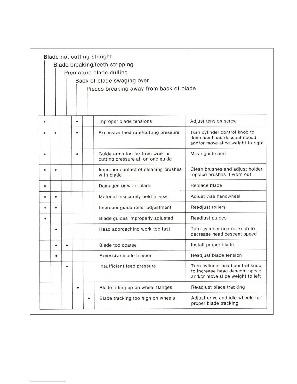
SAWING PROBLEMS & SOLUTIONS
6/02
18
Page 19

Section 3
ASSEMBLIES AND PARTS LIST
6/02
19
Page 20

6/02
MACHINE ASSEMBLY, Front View
ITEM PART NO. DESCRIPTION QTY
1 10002-01 Front Frame 1
2 10003-01 Rear Frame 1
3 10001-00 Bed 1
4 10066-00 Pivot Bar 1
5 13010-08 Shaft Locking Collar 2
6 10004-02 Right Leg 1
7 10005-02 Left Leg 1
8 10070-00 Balance Spring - includes carriage bolt and nut 1
9 10100-01 Spring Perch 1
10 10101-01 Outboard Bearing Casting – (uses 3/8” bolt – lockwasher - nut) 1
11 5527-00 Stock Stop Assembly 1
11A 5027-00 Holder Casting 1
11B 5213-00 Rod 1
11C 5028-00 Spring 1
11D 5200-00 Handle 1
12 5027-01 Stock Stop Mounting Bar 1
13 10006-01 Tip-off Block 1
14 10269-00A Coolant Drawer Pan 1
15 300405A Left Hand Blade Guard 1
16 300404A Right Hand Blade Guard 1
17
18 10268-06A Left Leg Pan 1
19 10268-05A Right Leg Pan 1
20 10093-00 Frame Handle 1
21 10229-00 Brush holder Guard 1
22 72295 Dake/Johnson Name Plate 1
23 71541 Submersible Coolant Pump – Electric 110 volt 1
PARTS NOT ILLUSTRATED
PART NO. DESCRIPTION QTY
10079-05 Motor, 230/460 volt, 60 Hz, 3 phase – 1 H.P. 1
10079-07 Motor, 110/230 volt, 60 Hz, 1 phase – 1 H.P. 1
10042-10 Motor Pulley – 5/8” Bore 1
10077-10 Drive Belt 1
10223-10A Pulley Guard 1
5107-00 Motor Hanger Base 1
5106-02 Frame Hanger Motor Base 1
5106-03 Motor Mounting Pin 1
300403A Frame Covers (Left and Right Hand Sides) 2
10230-10A Rear Frame Blade Guard 1
10271-00A Drive Wheel Drip Pan 1
10287-00 Strap, Wheel Pan 1
10286-00 Bar, Wheel Pan 1
70295 Thumb Screw – Drive Wheel Drip Pan 2
10209-01 Spring Bracket Top 1
10126-13A Lower Left Front Cover 1
10091-10 Frame Rest 1
300407A Drive Wheel Cover 1
300408A Idle Wheel Cover 1
300409A Drive & Idle Wheel Spoke Guards 2
300246 Wire Ties 12
20
Page 21
6/02
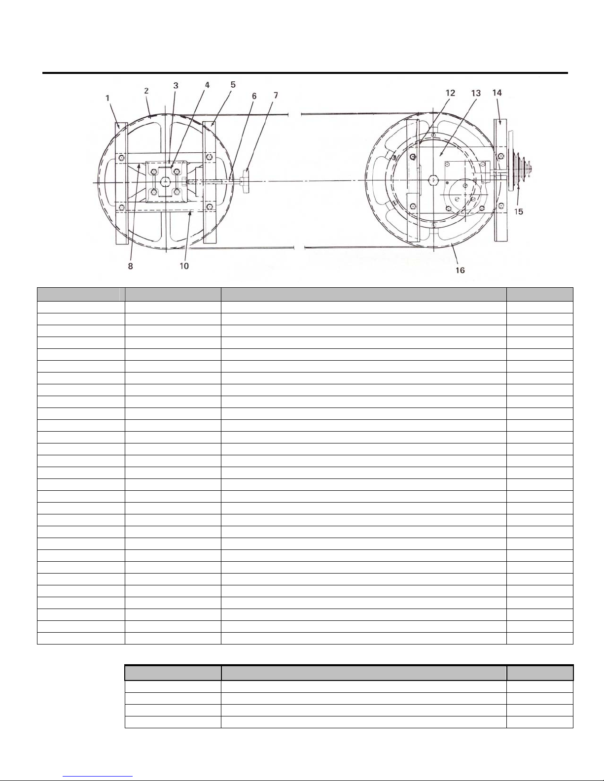
MACHINE ASSEMBLY, Top View
ITEM PART NO. DESCRIPTION QTY
1 10064-09 Idle Wheel and Frame Mounting Bracket (Outboard) 1
2 10510-02 Idle Wheel Assembly (J-10) 1
10010-02 Idle Wheel Only (J-10) 1
10510-04 Idle Wheel Assembly (JH-10) 1
13035-01 Idle Wheel Only (JH-10) 1
10062-00 Wheel Axle (J-10 & JH-10) 1
10134-01 Bearing Cup (J-10 & JH-10) 2
10134-02 Bearing Cone (J-10 & JH-10) 2
10135-00 Dust Collar (J-10 & JH-10) 2
10136-00 Snap Ring (J-10 & JH-10) 1
3 & 4 5011-01 Slide & Rocker Block Assembly 1
5 10064-08 Idle Wheel and Frame Mounting Bracket (Inboard) 1
6 & 7 10125-01 Tension Screw Assembly 1
8 10210-00 Slideway – Top 2
10 10067-00 Slideway – Bottom 1
12 10064-10 Drive Wheel and Frame Mounting Bracket (Inboard) 1
13 10063-00 Gear Box Mounting Plate 1
14 10064-06 Drive Wheel and Frame Mounting Bracket (Outboard) 1
15 10043-10 Driven Pulley – 3/4" Bore (Key – Part No. 71061) 1
16 10510-01 Drive Wheel Assembly (J-10) 1
10010-01 Drive Wheel Only (J-10) 1
10052-00 Ring Gear (Used on J-10 and JH-10) 1
10510-03 Drive Wheel Assembly (JH-10) 1
10010-03 Drive Wheel Only (JH-10) 1
10062-00 Wheel Axle (J-10 & JH-10) 1
10134-01 Bearing Cup (J-10 & JH-10) 2
10134-02 Bearing Cone (J-10 & JH-10) 2
10135-00 Dust Collar (J-10 & JH-10) 2
10136-00 Snap Ring (J-10 & JH-10) 1
PARTS NOT ILLUSTRATED
PART NO. DESCRIPTION QTY
70346 Wheel Mounting Bolt (3/4" – 16 x 1¼”) 2
14123 Wheel Mounting Bolt Nut (1" – 14) 2
70296 Wheel Mounting Bolt Lock Nut (1" – 14) 2
5143-00 Grease Fitting 1
21
Page 22
6/02
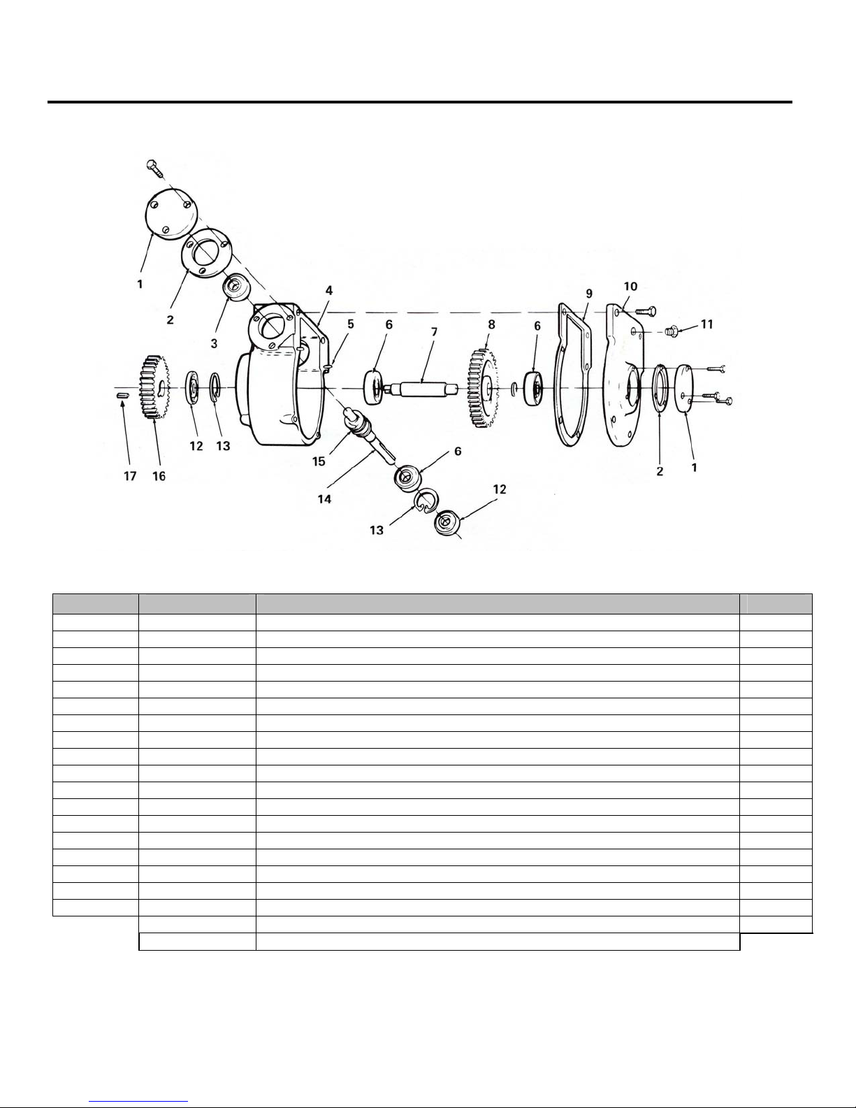
GEARBOX ASSEMBLY
ITEM PART NO. DESCRIPTION QTY
1 5047-00 Bearing Cap 2
2 5138-00 Cap Gasket 2
3 5073-00 Bearing 1
4 5044-00 Gear Case 1
5 5142-00 Dowel Pin 2
6 5072-00 Bearing 3
7 10049-00 Worm Gear Shaft 1
8 & 15 10051-51 Worm – Steel Worm & Gear Bronze Assembly (10051-00 & 10050-00) 1
9 13080-01 Cover Gasket 1
10 5045-00 Gear Case Cover 1
11 7368 Breather Vent 1
12 5137-22 Oil Seal 2
13 5136-00 Snap Ring 2
14 5048-00 Worm Shaft 1
15A 71061 Key (3/16 x 3/16 x 1¾”) 1
16 10053-00 Spur Gear (Set Screw – Part No. 43558) 1
17 10047-01 Key (3/16 x 3/16 x ½”) 1
26189 Woodruff Key (Not Shown) 2
10544-00 Gear Case Assembly Complete 1
714706 Bearing & Seal Kit (Includes Items 2,3,6,9,12 & 13)
22
Page 23
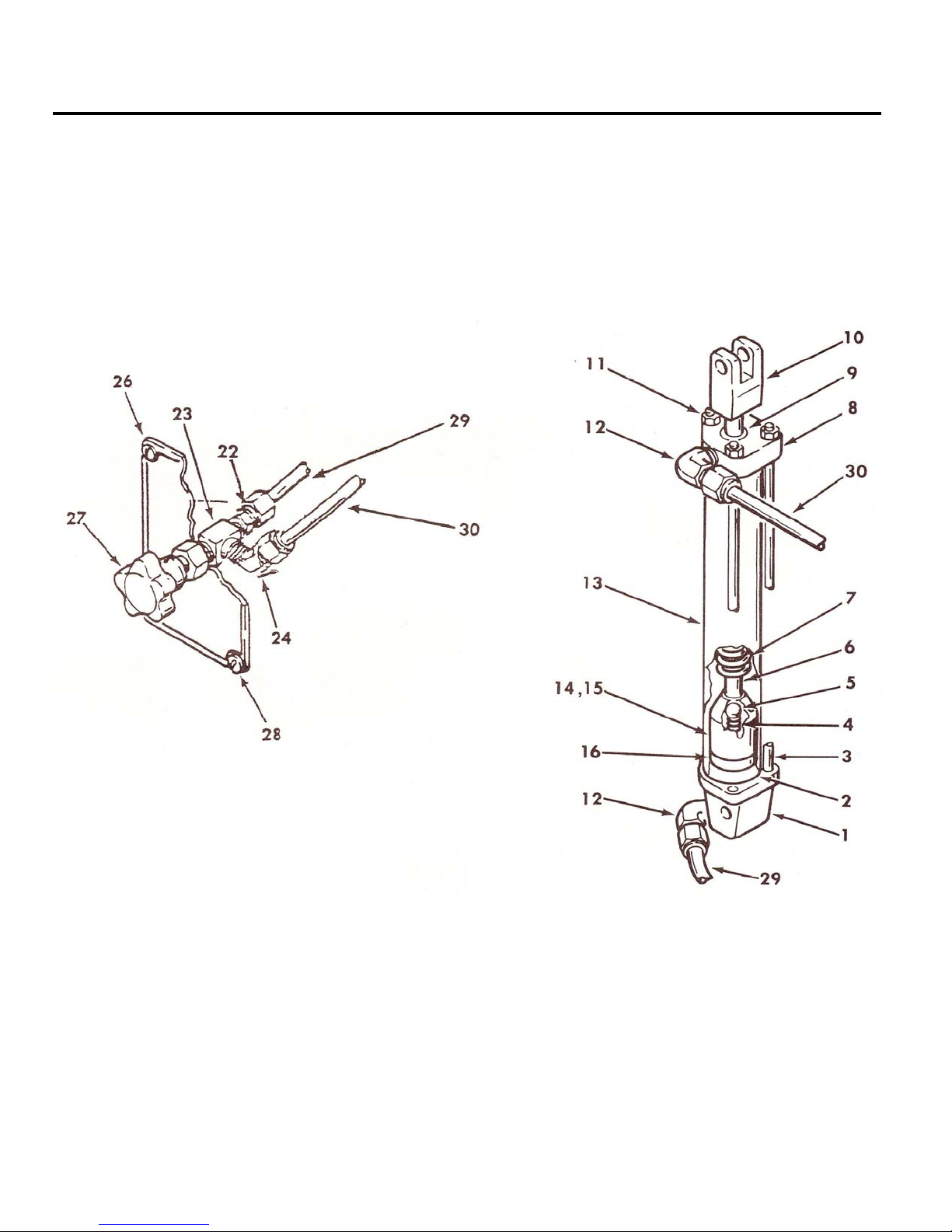
HYDRAULIC ASSEMBLY
6/02
23
Page 24

6/02
ITEM PART NO. DESCRIPTION QTY
1 10031-00 Cylinder Base 1
2 10203-03 Fiber Seal 2
3 10205-02 Tie Rod 3
4 5129-00 Spring 1
4A 5116-00 Spring – R Style included in repair kit. 1
5 17817 3/8 inch Ball 1
6 10204-02 Piston Rod 1
7 10033-00 Head Stop Spring 1
8 5030-10 Cylinder Head 1
9 10115-02 Head Seal (O-Ring) – New Models 1
9A 10115-03 Older Models Garlock Shaft Seal (1/2” ID x 7/8” OD x 1/8” Thick) 1
9B 13080-03 Older Models Garlock Shaft Seal (1/2” ID x .801” OD x 1/8” Thick) 1
10 10013-00 Yoke 1
11 43905 10-24 Nut 3
12 71357 Elbow (Includes furrow and nut) 2
13 10203-02 Cylinder Body 1
14 5119-00 Piston 1
15 5120-00 Piston Nut 1
16 5130-00 Leather Cup 1
10530-08 Control Valve Assembly 1
17 40600-00 Straight Fitting 2
18 1738 Nipple 1/4 x 2-1/2 1
19 70466 Reducer 3/8 x ¼ 1
20 588 3/8 Pipe Plug 1
21 1115 Tee ¼ 1
22 70465 Coupler 1/4 x 1/8 2
23 5131-00 Valve 1
24 44143
25 1329 1/8 Close Nipple 2
26 10030-00 Face Plate 1
27 13018-14 Knob 1
28 44349 8 x 32 Screw 4
29 40515-00 5/16 Tubing 7 ft. 1
30 40515-00 5/16 Tubing 8 ft. 1
31 5032-00
10530-10 Hydraulic Assembly (Includes Control Valve Assembly) 1
10530-09 Cylinder Assembly (Only) 1
90° St. Elbow
Oilier (Not Shown) *Note: Items 18-21 are not needed when saw is
equipped with oilier
714717
10530-01 Rod & Piston Assembly (Includes Items 4,5,6,14,15 & 16)
Hydraulic Cylinder Repair Kit (Includes Items 2, 4, 4A, 5, 9, 9A,
9B & 16)
1
1
24
Page 25
6/02
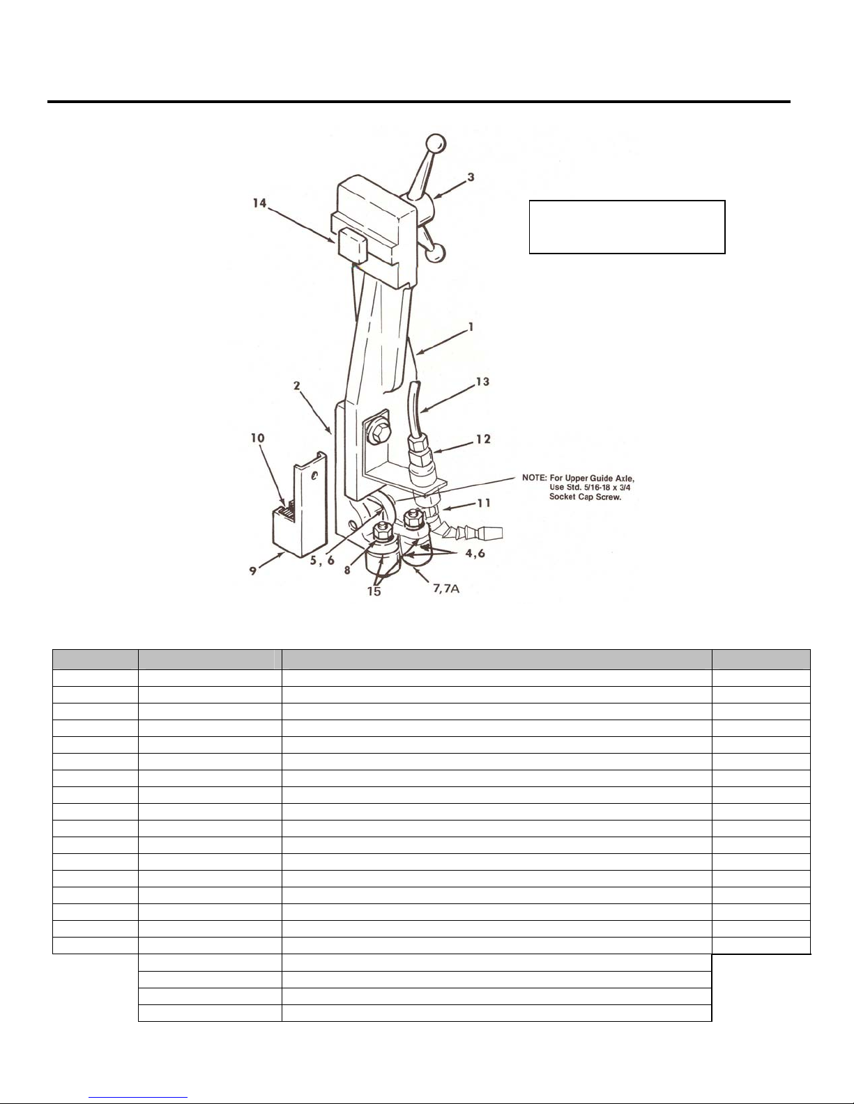
GUIDE ARM ASSEMBLY
ITEM PART NO. DESCRIPTION QTY
1 10019-10 Guide Arm LH & RH 1
2 10020-10 Guide Holder 1
3 10084-01 Guide Arm Tightening Handle 1
4 10025-01 Side Guide Bearing 2
5 5026-00 Upper Guide Bearing 1
6 5023-01 Upper Guide Bushing 1
7 10022-02 Inside Concentric Axle with Nut & Washer 1
7A 5075-00 Side Guide Bushing 1
8 10022-10 Outside Eccentric Axle with Nut & Washer 1
9 5122-00 Brush Holder 1
10 5133-S Blade Cleaning Brush Kit – 6 Pairs 1
11 715342 Coolant Nozzle Assembly 1
12 34528 Tube Fitting, Poly-Tite 1
13 67762 Tubing 10 ft.
14 10512-10 T-Bolt 1
15 70462 Spacer Washer (JH Model Only) 8
10519-10 Guide Arm Assembly Complete LH & RH 2
10520-10 Guide Holder Assembly (Includes Items 2, 4, 5, 6, 7, 8 & 15)
715104 Guide Bearing Kit (Includes Items 4, 5, 6&7A) Will outfit 2 arms
75958 Blade, J-Saw – 3/4” x 137” x .035” 5/8 VP – Bi-Metal
75957 Blade, JH-Saw – 1” x 137” x .035” 5/8 VP – Bi-Metal
T-slot Dimension
5/8” New Style
25
Page 26

6/02
VISE UNIT
ITEM PART NO. DESCRIPTION QTY
1 10007-00 Hold Down Block 1
2 10099-00 Vise Lift 1
3 5200-00 Handle 1
4 10008-00 Movable Vise Jaw (Bolt – Part No. 43348) 1
5 10009-00 Stationary Vise Jaw (Bolt – Part No. 43348) 1
7 10116-00 Lift Pin 1
8 10201-00 Vise Nut Plate (Self Tapping Screw (10-24) – Part No. 43882) 2
9 10016-00 Vise Nut 1
10 10015-10 Vise Screw 1
11 10014-00 Handwheel 1
12 70464 Stop Collar 1
13 70287 Drive Pin 1 or 2
26
Page 27
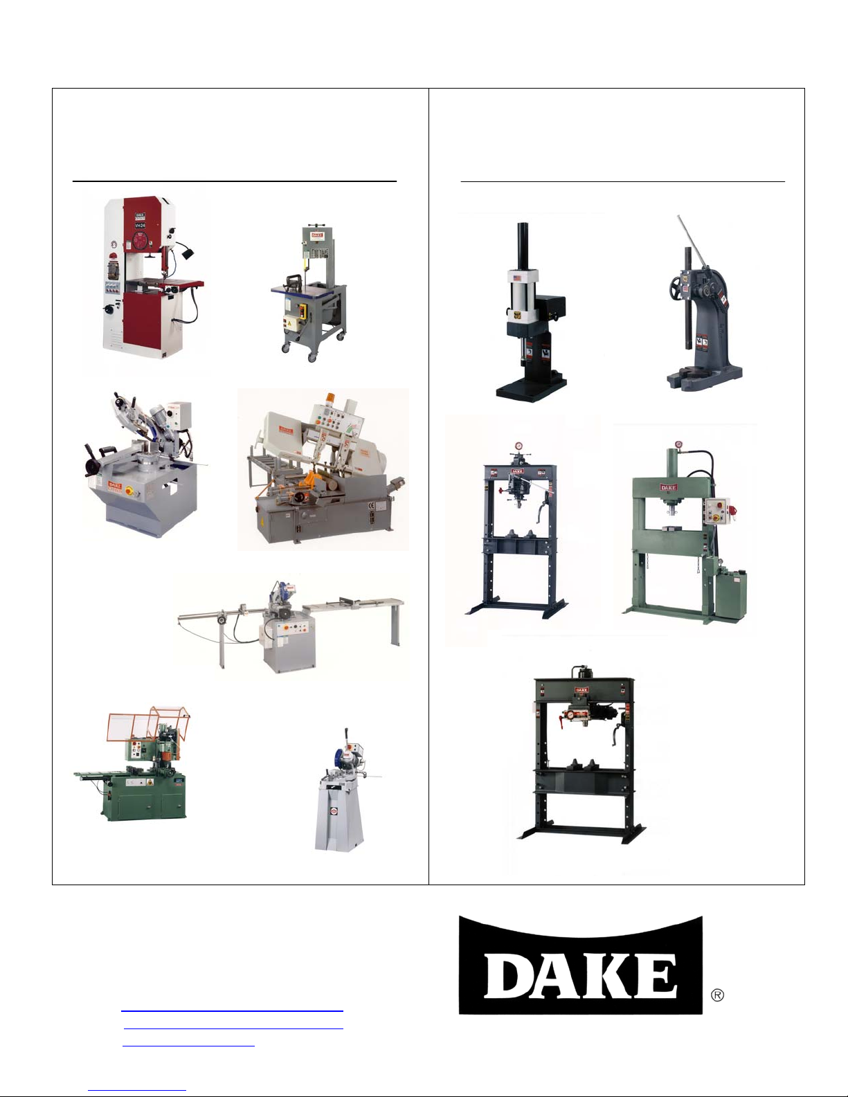
Metal Band Saws & Cold Saws for Precise,
p
Low-Cost Service Free Sawing.
Horizonal Bandsaws, Vertical Bandsaws and Cold Saws
competitively priced.
DAKE Division of JSJ
724 Robbins Road
Grand Haven, MI 49417
Phone: 1-800-937-3253 616-842-7110
Fax: 1-800-846-3253 616-842-0859
E-mail: customerservice@dakecorp.com
technicalservice@dakecorp.com
Web: www.dakecor
.com
6/02
Arbor and Hydraulic Presses for All Your
Application needs.
A complete line of Arbor, H-Frame and custom engineered
Hydraulic Presses for production, maintenance and
research work.
27
 Loading...